Core & Cavity Design
AIM : Create the Core and cavity blocks for the switch bezel designed in the earlier challenge.
METHODS AND PROCEDURE FOLLOWED :
- Creating a Parting surface from class A.
- Creating a Core design & core block by close surface.
- Creating a Cavity design & cavity block by close surface.
- Creating a Parting line.
PROCEDURE :
- Creating a parting surface from class A :
- Made a boundary to a class A surface.
- Extrapolate it.
- Trimed class A with Class C.
- After that trimmed it with Class B.
Here we get the parting surface with a component.
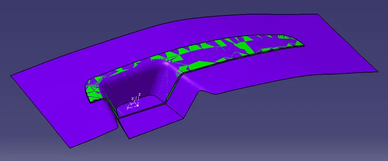
- Creating a Cavity design & cavity block by close surface :
First make the positioned sketch to get a wall of the core & cavity mould.
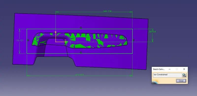
Extrude that sketch & trim it along the parting surface in the correct direction.
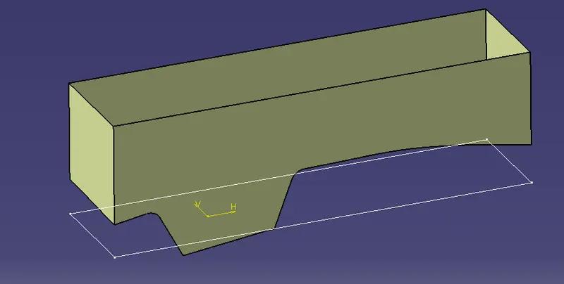
Fill it using the create boundary and join both of them.
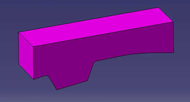
Created the Solid Core Body using close feature
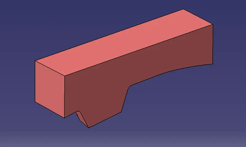
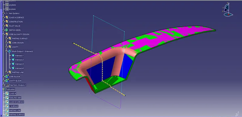
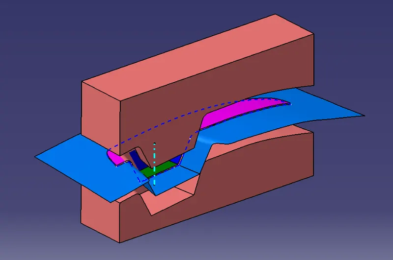
Intersect the core
First element : ZX plane
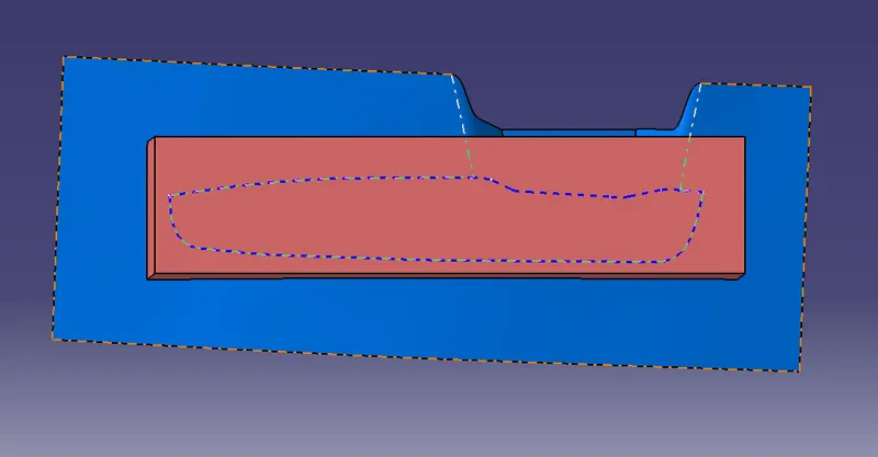
Second element : Close surface of core, parting surface with component and switch bezel body.
Highlight the intersections.
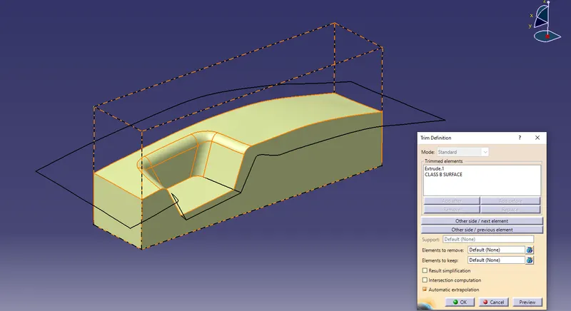
- Creating a cavity design & cavity block by close surface :
Trim the extrude and Class B surface together to make sure trimming in the correct required direction to avoid component area. To get molton filler area.
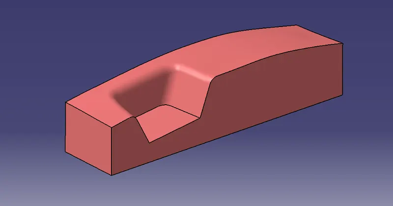
Repeat the process followed for to make core design and we get the final cavity block (Closed body) ,
- Creating a Parting line :
Use a split or intersection command to get parting line,
- First join ClassA and Class C surface.
- Intersect or split it with Class B surface & we got the Parting line.
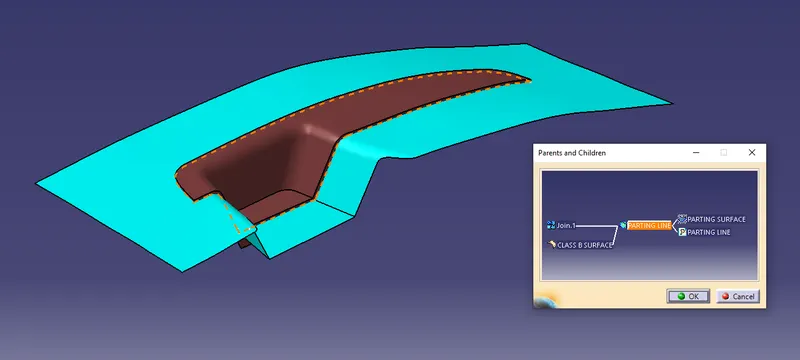
Parting surface : Split the Parting surface with component to Parting line to get exact parting surface. The surface which is outside the component is the Parting surface.
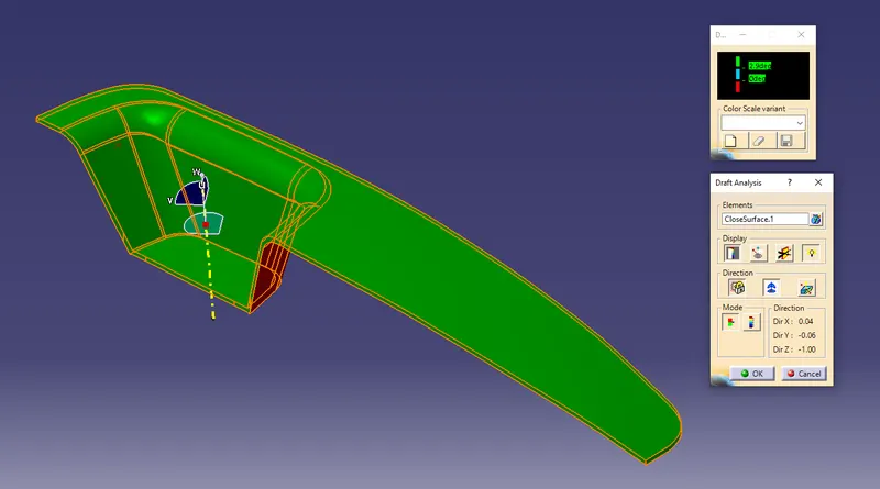
- Screenshots of the Draft analysis report for both the switch bezel plastic component.
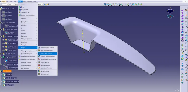
To perform draft analysis, Go to the insert > Analysis > Feature draft analysis.
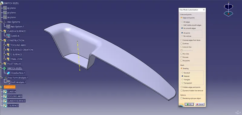
Switch customize view parameters and select material.
Click on the compass icon and align it with the tooling axis & click on the surface, we will get our results.
From the below image we can see that the surface in green colour has a more than 2.9° draft which is most required for tooling feasibility. Also see the color variant display box.
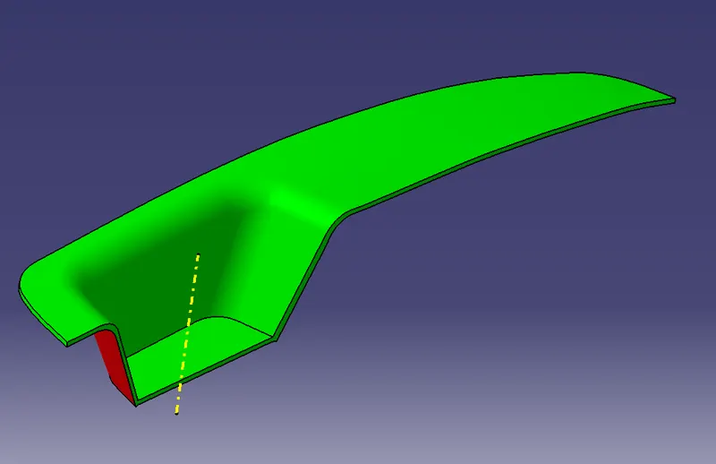
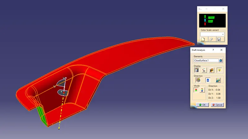
By inverting the draft direction we get the below image.
Below image shows running point draft analysis.
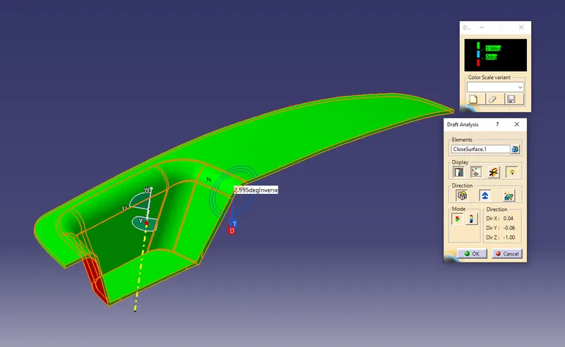
Below image shows full draft angle.
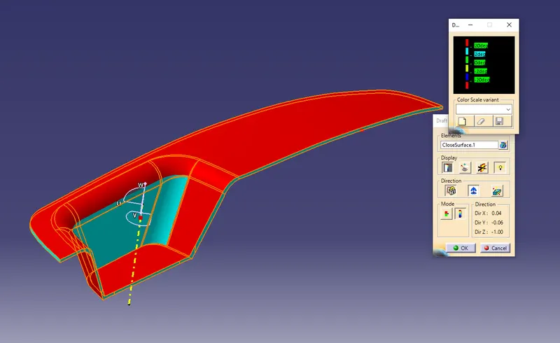
Image of the model with the proper colour code of the draft angle in various orientations ( Isometric, Front, Side and Top view).
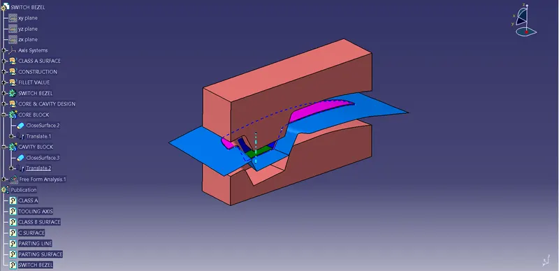
Isometric View :
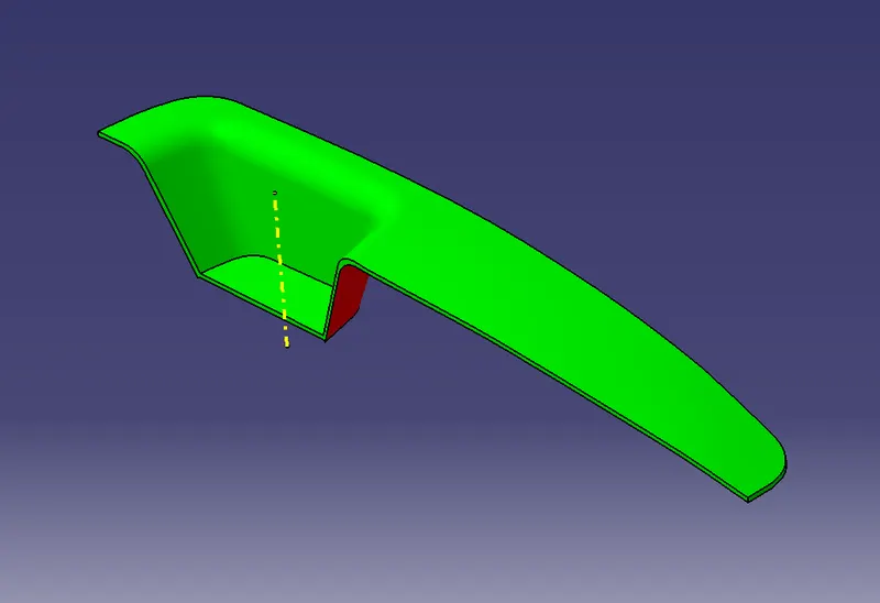
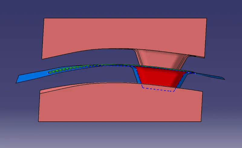
Front View :
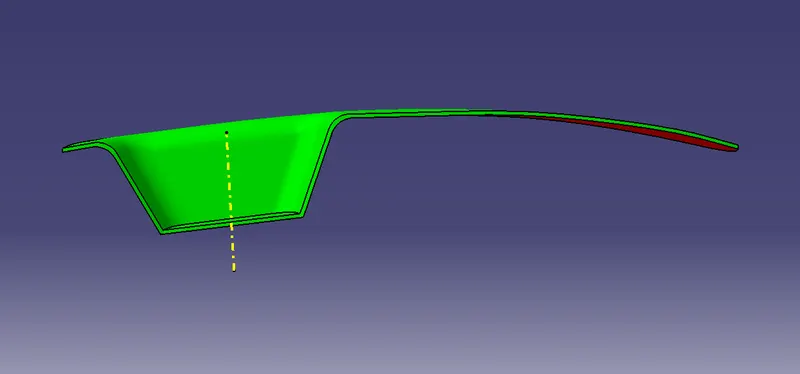
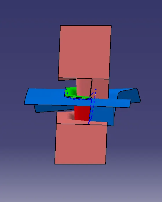
Side view :
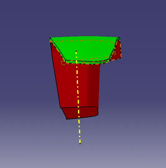
Top view :
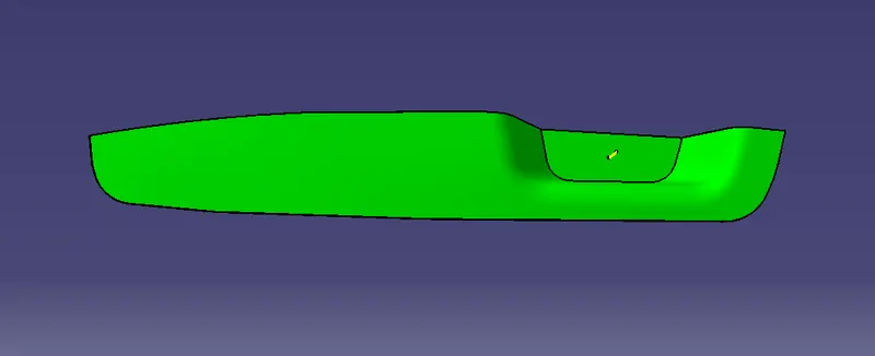
- Screenshots of the core and cavity blocks in various orientations (Isometric, Front, Side, and Top View).
Conclusion : Created a Core & cavity block and performed draft analysis on switch bezel component.