Coin Holder Design
AIM : Create the Coin Holder Plastic component through the given Class-A surface. To begin with, the tooling axis for the given Class-A Surface should be created meeting the requirements of the draft angle and at the end perform the Draft analysis on the model.
METHODS AND PROCEDURE FOLLOWED :
Take the Thickness of the component to be 2.5 mm
- Creating a Tooling Axis
- Creating a Class B & C surface
- Creating a solid body using a close surface
- Creating a solid body by using a closed surface
- Performing a draft analysis
Ensured that the given Class A surface in a single boundary using boundary command and made an intersection.
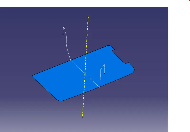
- Creating a tooling axis by steps as given below :
- Extract a base surface
- Make a point on a surface by zero coordinates.
- Then make a line from that point by Y direction
- Tooling axis is formed and name it in a geometrical set
- Creating a Class B surface from given Class A surface :
Followed the process for making a Class B surface as given below,
- Extract it separately
- Un-trim it
- Extrapolare it then made an offset of 2.5mm.
1. Base :
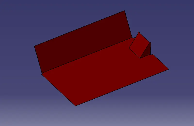
Repeated this process for all the side walls and then for the outer flange.
2. Side walls :
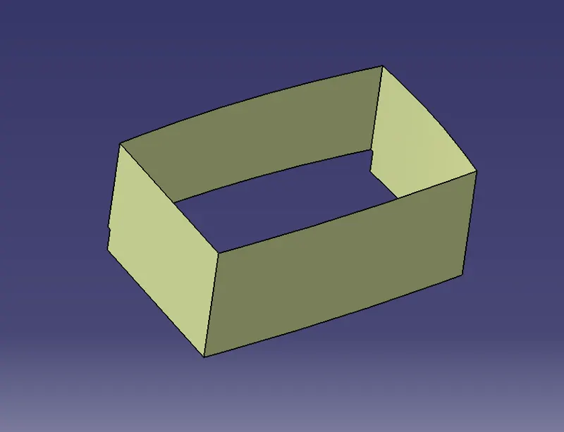
3. Outer flange :
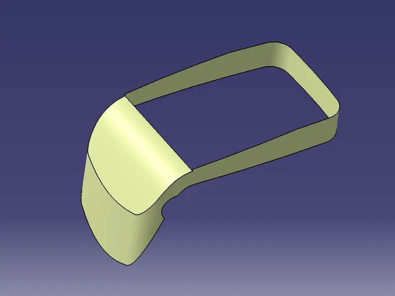
Outer flange should be offsetted in an inward direction.
Initial trim :
After completing all this process separately on surfaces give a trim in a separate geometrical set and name it as an initial trim.
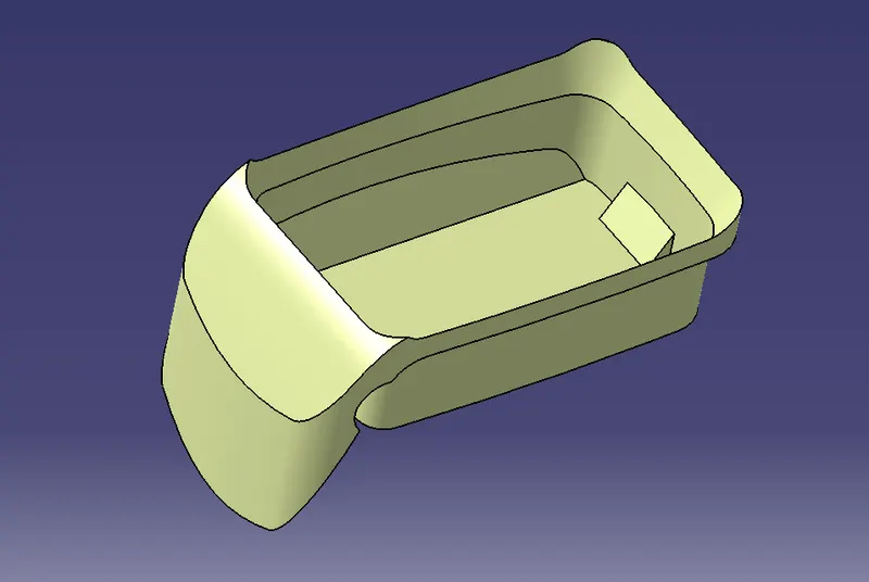
Give edge fillets where it is required by measuring the value from a class A
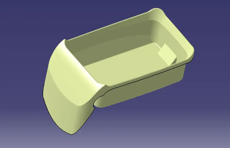
- Creating a Class C surface from Class B :
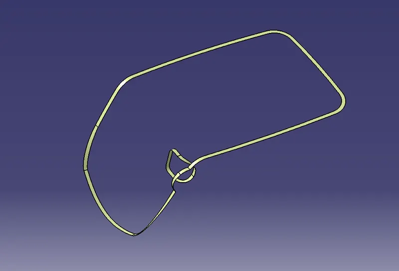
- Extract the boundary of an outer flange and hole which is mounted on a side wall by a multiple extract.
- Also extract the surface which is connected with the boundary curve.
And here we get a Class C surface as given shown in below image
Final trim :
After getting all Class A,B & C surface
First join a Class A and C surface
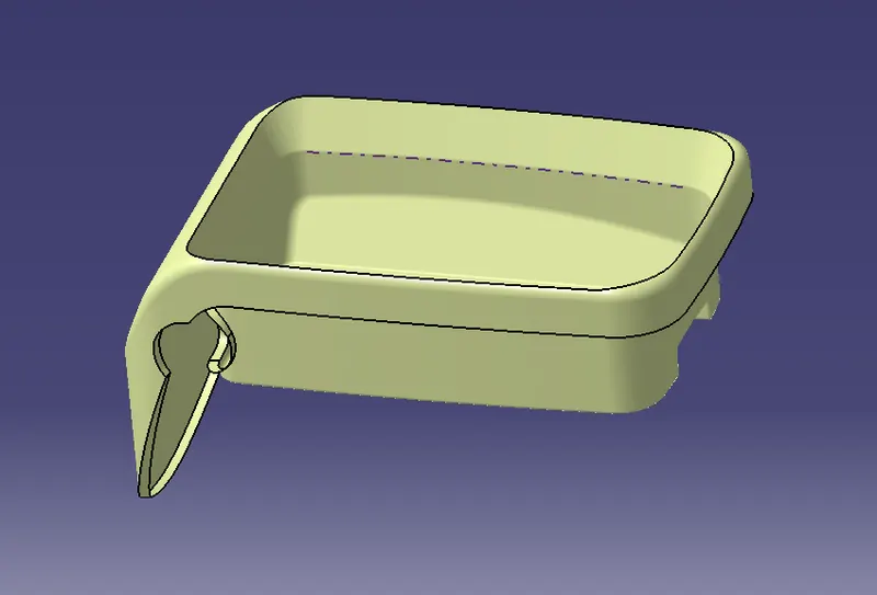
Then trim it from a Class B surface
The final output surface is shown in below image
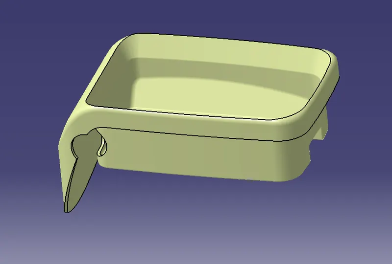
- Creating a solid body by using a closed surface :
Solid body is created by a closed surface feature in the Part Design workbench in the defined partbody. This is our design output shown as given below in various orientations.
Isometric view
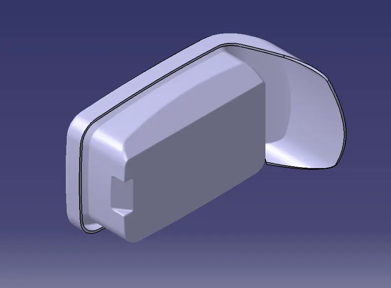
Front view
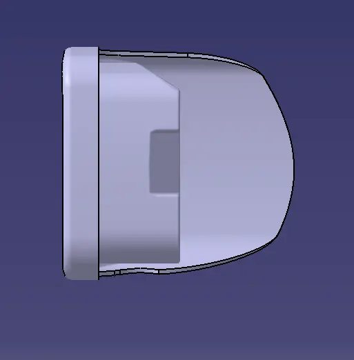
Side view
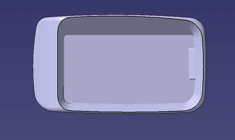
Top view
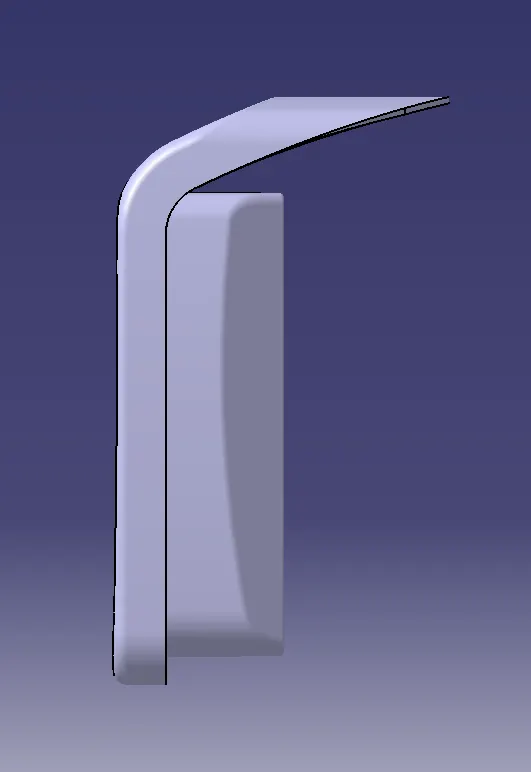
- Performing a draft analysis :
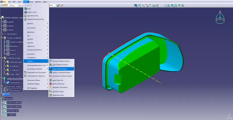
To perform draft analysis, Go to the insert > Analysis > Feature draft analysis.
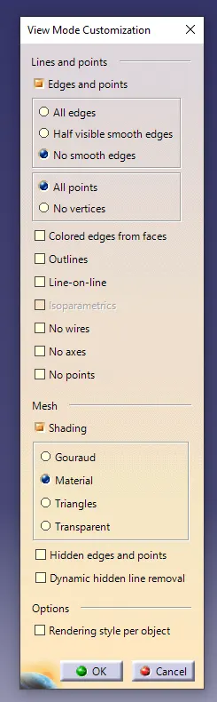
Switch customize view parameters and select material.
Click on the compass icon and align it with the tooling axis & click on the surface, we will get our results.
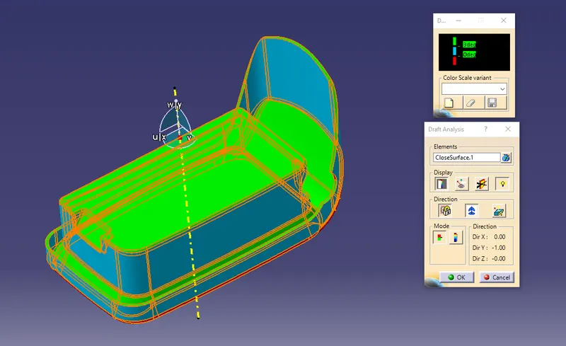
From the above image we can see that the surface in green colour has a more than 3° draft which is most required for tooling feasibility. Also see the color variant display box.
By inverting the draft direction we get the below image.
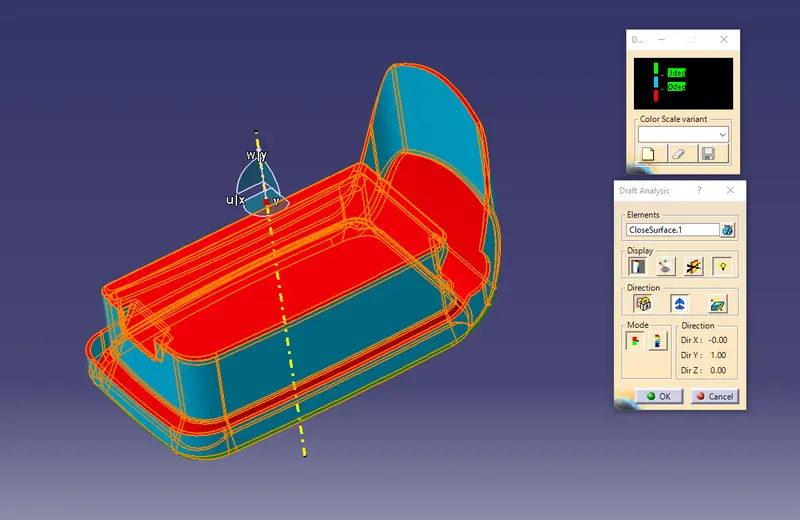
Below image shows running point draft analysis.
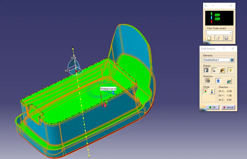
Below image shows full draft angle.
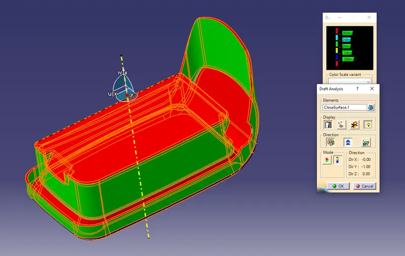
Image of the model with the proper colour code of the draft angle in various orientations ( Isometric, Front, Side and Top view).
Isometric View :
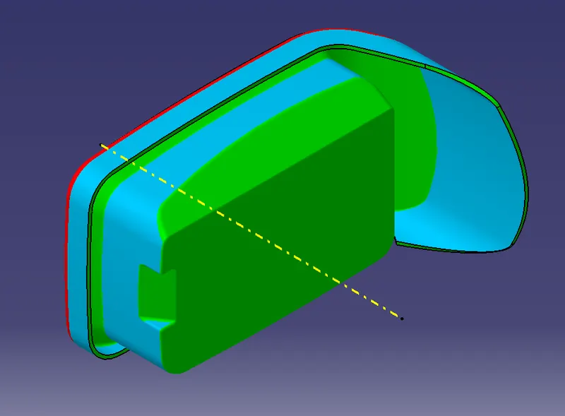
Front View :
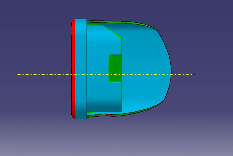
Side view :
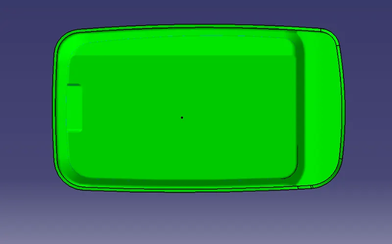
Top view :
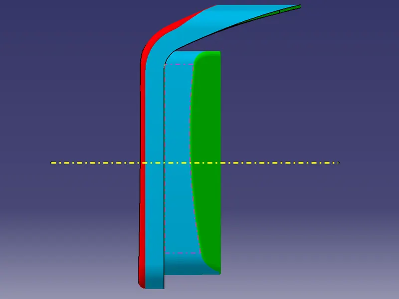
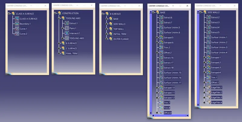
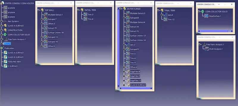
Images of the expanded Tree structure of the Geometrical set, part body and publications.
Conclusion : Created the COIN HOLDER Plastic component through the given Class-A surface and performed Draft analysis.