Rankine Cycle Simulator using matlab
Aim : plot the h-s and T-s plots rankine cycle using matlab.
Theory :
1. Rankine cycle is used to compare the working of steam power plant.
2. In this context , plotting ideal Rankine cycle.
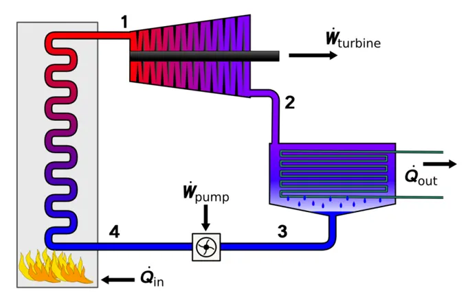
3. Above figure , shows the exterior design of steam power plant , Rankine cycle
4. Contains Boiler , Condensor , Turbine , Pump.
5. Use of pump - Convert mechanical energy into hydraulic energy (pressure energy).
6. Boiler - Convert liquid to vapour meadium of working fluid.
7. Turbine - Converts hydraulic energy into mechanical energy(with help of shaft) connnected to generator.
8. Condensor - Removes heat from fluid , converts vapour to liquid form.
Processes in Rankine cycel :
1. 1-2 - Isentropic expansion.
2. 2-3 - Isobaric heat rejection.
3. 3-4 - Isentropic compression.
4. 4-1 - Isobaric heat addition.
Equations used :
1. Work generated by turbine :
`w_t = h_1 - h_2.`
2. Work absorbed by pump :
`w_p = h_4 - h_3.`
3. Net work :
`w_(nt) = w_t - w_p .`
4. Heat absorbed (q1):
`Q_a = h_1 - h_4 .`
5. Efficinecy (`eta`):
`eta = frac{w_t - w_p}{Q_a}*100%`
6. Entalpy with quality factor:
`h = h_f + x*(h_g - h_f)`
here 'x' is quality factor , repreasents amoundof vapour presents in the mixture.
Code snippet :
close all ;
clear all ;
clc ;

fprintf('                        RANKINE CYCLE SIMULATOR\n\n')
fprintf('1-2 is I sentropic Expansion in the Turbine \n')
fprintf('2-3 is Const Pressure Heat Rejection by yhr condensor \n')
fprintf('3-4 is Isentropic Compression in the Pump \n')
fprintf('4-1 is Const Pressure Heat Addition by the Boiler \n')
p1 = input('Enter the Pressure at the Turbine Inlet (in bar):' );
t1 = input('Enter the Temperature at the Turbine inlet (in Degree Celcius):');
p2 = input('Enter the pressure at the Condensor (in bar):');
fprintf('------------------------------------------------------------------------------------ \n')
fprintf('                              RESULTS \n\n')


%state points 1
%t1 = 400;
h1 = XSteam('h_pT',p1,t1);
s1 = XSteam('S_PT',p1,t1);

% state points 2
% turbine under isentropic expansion so,
s2 = s1;
% quality factor at state 2
sg2 = XSteam('sV_p',p2);
sf2 = XSteam('sL_p',p2);
if s2 < sg2
    x2 = (s2 - sf2)/(sg2-sf2);
else
    x2 = 1;
end
% working fluid in l+v state as x2<1.
% so
hf2 = XSteam('hL_p',p2);
hg2 = XSteam('hV_p',p2);
h2  = hf2 + (x2*(hg2 - hf2));
t2 = XSteam('T_ph',p2,h2);


% state point 3
% entire liquid state
% so , h3 = hf3 = hf2
% s3 = sf2;
h3 = hf2;
s3 = sf2;
p3 = p2;
t3 = XSteam('T_ph',p3,h3);


% state point 4
% isentropic compression process
s4 = s3;
p4 = p1;
h4 = XSteam('h_ps',p4,s4);
t4 = XSteam('T_ph',p4,h4);

% state point 5
% at saturated liquid state , at pressure -> p1.
p5 = p1;
h5 = XSteam('hL_p',p5);
s5 = XSteam('sL_p',p5);
t5 = XSteam('T_ph',p5,h5);


% state point 6
% saturated vapout properties at pressure = p1.
p6 = p1;
h6 = XSteam('hV_p',p6);
s6 = XSteam('sV_p',p6);
t6 = XSteam('T_ph',p6,h6);

fprintf(' %s %46s \n','At State Point 1:','At state Point 4:')
fprintf(' %3s %4.2f %2s %33s %4.2f %2s \n','P1 is %4.2f:',p1,'bar','P4 is : ',p4,'bar')
fprintf(' %3s %5.2f %2s %29s %6.4f %2s \n','T1 is :',t1,'Deg celsuis','T4 is : ',t4,'Deg celsius')
fprintf(' %3s %7.6f %2s %30s %7.4f %2s \n','H1 is :',h1,'KJ/Kg','H4 is : ',h4,'KJ/Kg')
fprintf(' %3s %5.4f %2s %33s %5.4f %2s \n','S1 is :',s1,'KJ/Kg-K','S4 is : ',s4,'KJ/Kg-K')

%work calculations
wt = h1 - h2;                         % turbine work
wp = h4 - h3;                         % pump work
wnet = wt - wp;                       % Net work
qin = h1 - h4;                        % q absorbed from boiler
eff  = ((wt - wp)/qin)*100;           % efficiency of cycle

fprintf('\n')
fprintf(' %s %38s %6.4f %2s \n','At State Point 1:','wt is : ',wt,'KJ')
fprintf(' %3s %4.2f %2s %39s %4.2f %2s\n','P2 is :',p2,'bar','wp is : ',wp,'KJ')
fprintf(' %3s %5.2f %2s %32s %6.4f %2s \n','T2 is :',t2,'Deg Celsius','wnet is : ',wnet,'KJ')
fprintf(' %3s %7.6f %44s %5.4f %s \n','H2 is :',h2,'efficiency is : ',eff,'%')
fprintf(' %3s %5.4f %2s \n','S2 is :',s2,'KJ/Kg-K')
fprintf(' %3s %5.4f','X2 is :',x2)
fprintf('\n')


fprintf('\n')
fprintf(' %s \n','At State Point 3:')
fprintf(' %3s %4.2f %2s \n','P3 is : ',p3,'bar')
fprintf(' %3s %5.2f %2s \n','T3 is : ',t3,'Deg Celsius')
fprintf(' %3s %7.6f %2s \n','H3 is : ',h3,'KJ/Kg')
fprintf(' %3s %5.4f %2s \n','S3 is : ',s3,'KJ/Kg-K')


% for dom plotting in T vs Entropy
tic
t = linspace(0,1000,28000);

for i = 1:length(t)
    sl(i) = XSteam('sL_T',t(i));
    sv(i) = XSteam('sV_T',t(i));
end
a = toc;

% for dom plotting in Enthalpy vs Entropy
tic
t = linspace(0,1000,28000);

for i = 1:length(t)
    hl(i) = XSteam('hL_T',t(i));
    hv(i) = XSteam('hV_T',t(i));
    sle(i)  = XSteam('sL_T',t(i));
    sve(i)  = XSteam('sV_T',t(i));
end
a = toc;

subplot(1,2,1)
% Entropy vs temperature plot
plot([s1,s2],[t1,t2])
hold on
plot([s2,s3],[t2,t3])
plot([s3,s4],[t3,t4])
plot([s4,s5],[t4,t5])
plot([s5,s6],[t5,t6])
plot([s6,s1],[t6,t1])

% for dom plot
plot(sl,t,'LineStyle','--')
plot(sv,t,'LineStyle','--')

% labeling
xlabel('Entropy(KJ/Kg-K)')
ylabel('Temperature(K)')
title('Entropy vs temperature of rankine cycle simulator')
legend('turbine','condensor','pump','boiler - specific haet','boiler-latent heat')

ax = gca;
ax.XLim = [-2,10];
ax.YLim = [-100,600];

subplot(1,2,2)
% ENthalpy vs Entropy plot
plot([s1,s2],[h1,h2])
hold on
plot([s2,s3],[h2,h3])
plot([s3,s4],[h3,h4])
plot([s4,s5],[h4,h5])
plot([s5,s6],[h5,h6])
plot([s6,s1],[h6,h1])

% for dom plot
plot(sle,hl,'LineStyle','--')
plot(sve,hv,'LineStyle','--')
as = gca;
as.YLim = [-10,3800];

% labeling
xlabel('Entropy(KJ/Kg-K)')
ylabel('Enthalpy(KJ/Kg)')
title('Entropy vs Enthalpy of rankine cycle simulator')
legend('turbine','condensor','pump','boiler - specific haet','boiler-latent heat','Location','northwest','NumColumns',2)
Explanation of code:
1. clear the data on present interface.
2. Printed the comment on command window using 'fprintf'.
3. Calculated state point properties using 'XSteam' library.
4. Calculated quality factor using equation mentioned in code and above functions.
5. Printed the command in the specified format.
6. plotted the h-s and t-s of Rankine cycle simulator using plot command.
7. Set the axis limits using axes properties , (gca).
8. Labled the plots.
Outputs :
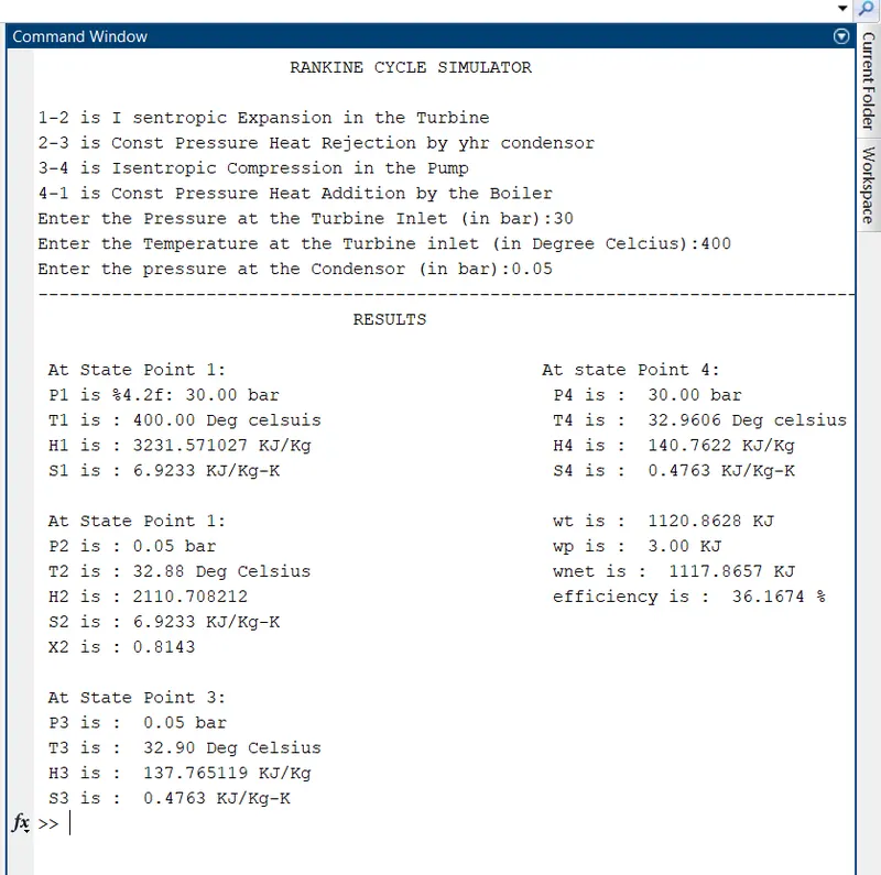
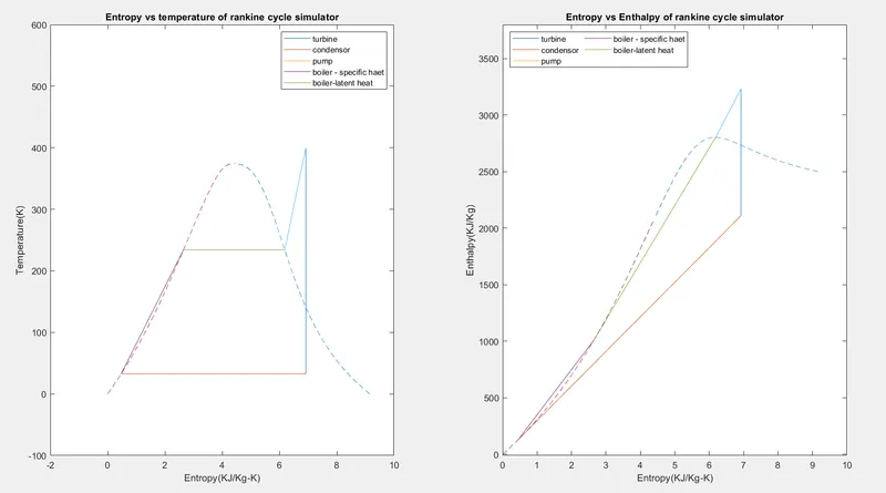
H-s and T-s plots of Rankine cycle:
Conclusion :
1. Shown the output in specified format.
2. plotted the h-s and t-s curves of Rankine cycle.