Radar Mast & Final Assembly of Yacht
1. INTRODUCTION:
A yacht is a sail or power vessel used for pleasure, cruising, or racing. There is no standard definition, so the term applies to such vessels that have a cabin with amenities that accommodate overnight use. To be termed a yacht, as opposed to a boat, such a pressure vessel is likely to be at least 33 feet (10 m) in length and may have been judged to have good aesthetic qualities. Originally, all yachts were made of wood, using a wooden keel and ribs, clad with planks. These materials were supplanted with iron or steel in steam yachts. In the 1960s fiberglass became a prevalent material. These materials and others continue in use. Whereas yachts of 79 feet (24 m) and below may be constructed of fiberglass, larger yachts are more likely to be constructed of steel, aluminum or composite fiber-reinforced plastic.
Parameters – I refers to the constraints whose values determine the shape or geometry of the model or assembly.
Design intent – Is how the creator of the part wants to respond to changes and updates.
Features – It refers to the building blocks of part. They are the shapes and operations that construct a part.
Building a model in SolidWorks usually starts with a 2D sketch. The sketch consists of geometry such as points, lines, circles,
arcs, splines and fillets. Dimensions are made in order to define the size and position of the geometry in a 2D plane. The dimensions in the sketch can be controlled independently, or by another parameter inside or outside the sketch.
OBJECTIVE:
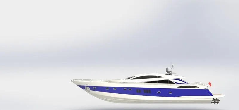
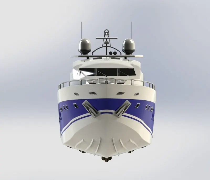
1. To create individual parts of an Sunseeker Predator Yacht using SolidWorks
2. To assemble all those individual parts into the bike titled “Sunseeker Predator Yacht”
3. To generate a photorealistic model and render that using photoview 360 and SolidWorks Visualize.
METHODOLOGY:
1. Part Modelling in SolidWorks
2. Assembly in SolidWorks
3. Photo Realistic Rendering using SolidWorks Photoview 360 & SolidWorks Visualize 2018
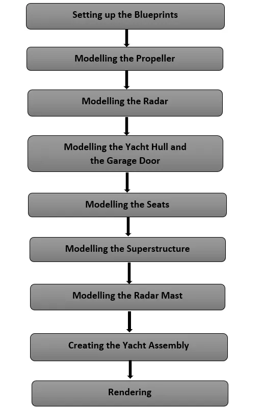
Yatch parts
1. Propeller
2. Radar
3. Hull
4. Garage Door
5. Front Seat
6. Middle Seat
7. Rear Seat
8. Superstructure
9. Radar Mast
FEATURES USED:
Split Line: The Split Line. tool projects an entity (sketch, solid, surface, face, plane, or surface spline) to surfaces, or curved or planar faces. It divides a selected face into multiple separate faces.
Projected Curves: it is a tool used to form 3D curves from two 2D curves from two different planes.
Extrude Boss/Base: Extrude tool is used to extend a sketched profile in one or two directions as either a thin feature or a solid feature.
Revolve Boss/Base: Revolves a sketch or selected sketch contours around an axis to create a solid feature.
Swept Boss/Base: Sweeps a closed profile along an open or closed path to create a solid.
Extrude Cut: Cuts a solid model by extruding a sketched profile in one or two directions.
Revolve Cut: Cuts a solid model by revolving a sketched profile around an axis.
Linear Pattern: Patterns features, faces and bodies in one or two linear direction.
Shell: Hollows out a part, leaving open the faces selected and creating thin-wall features on the remaining faces. If no face is
selected, it creates a hollow model.
Mirror: Mirrors features, faces, and bodies about a plane or a planar face.
Combine: This function adds two bodies together and keep the area that is common to them.
Extrude Surface: Extrudes a sketch or sketch contours in one of two directions to create a surface feature.
Revolve Surface: Revolves a sketch or selected sketch contours around an axis to create a surface feature.
Swept Surface: Sweeps a closed profile along an open or closed path to create a surface feature.
Lofted Surface: Creates a lofted surface between two or more profiles or sketches.
Boundary Surface: Creates a surface between profiles that can be a tangent or curvature, continuous in all directions.
Filled Surface: Patches a surface within a boundary defined by edges, sketches or curves.
Ruled Surface: Inserts ruled surfaces in a specified directed from edges
Knit Surface: Combines two or more adjacent non-intersecting surfaces into a single surface body.
COMPONENT MODELLING
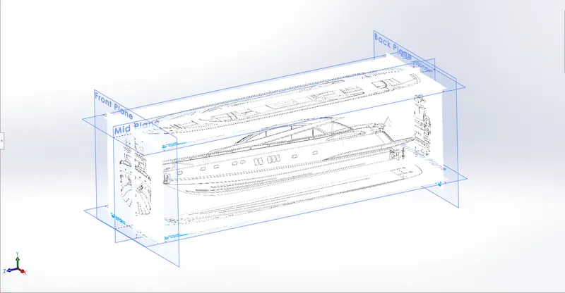
Blue print
1. Propeller
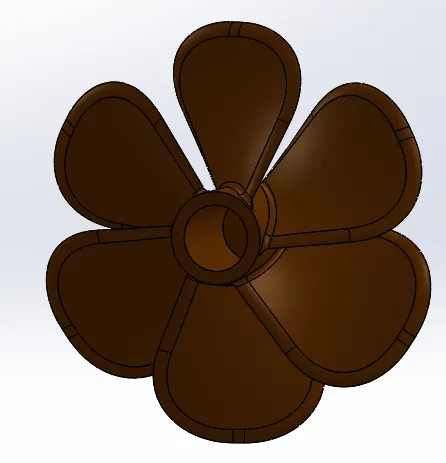
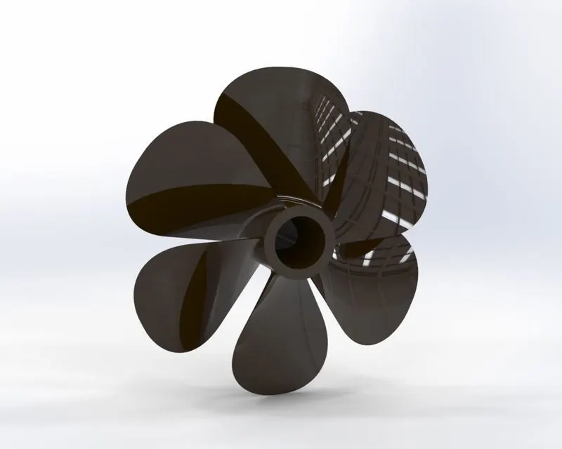
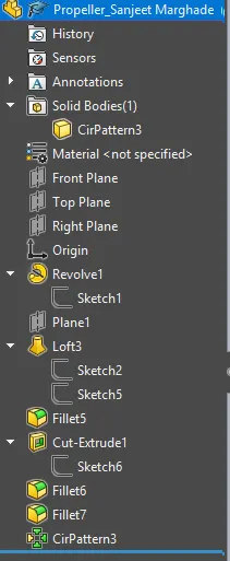
A propeller is a device with a rotating hub and radiating blades that are set at a pitch to form a helical spiral, which when rotated exerts linear thrust upon a working fluid, such as water or air.
Features:Line,Circles,Revolve,Loft,Circular Pattern,Extrude Cut,Fillet.
2. Radar
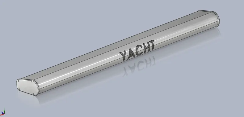
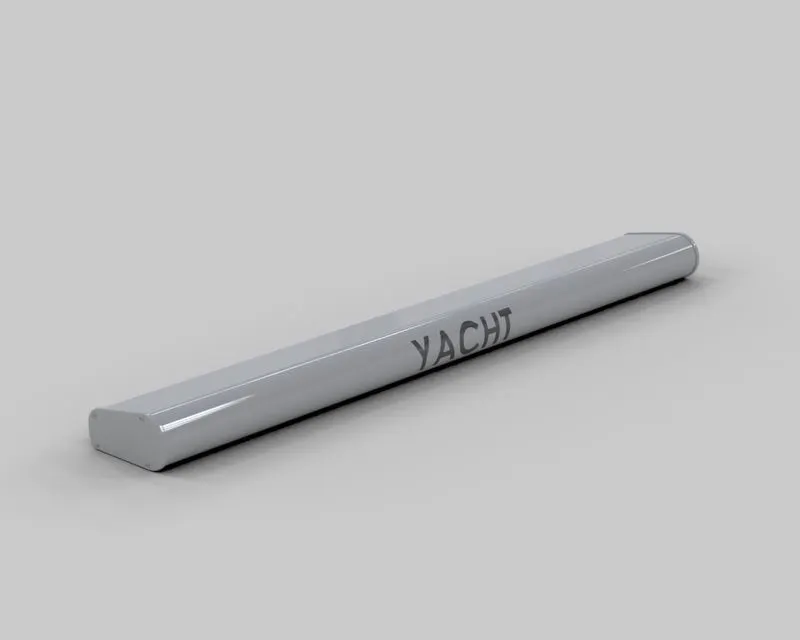
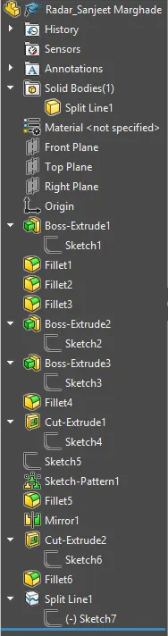
Radar is a part of a system which detects the environment conditions, other ships and land obstacles and helps maneuver through them.
Features:Lines,Circles,Rectangle,Extrude Boss/Base,MirrorText Projection,Fillet.
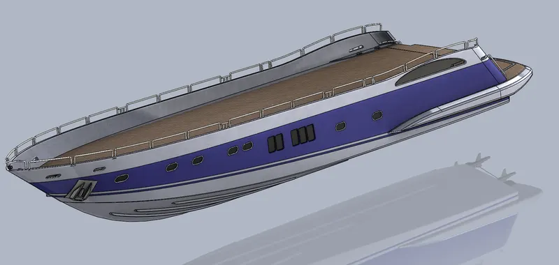
3. Hull
The Hull is a watertight body of a ship or boat. This may open at the top or may be fully or partially covered with a deck. Atop the deckmay be a deckhouse and other superstructures. The line where the hull meets the water is called the Waterline.
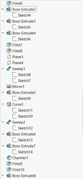
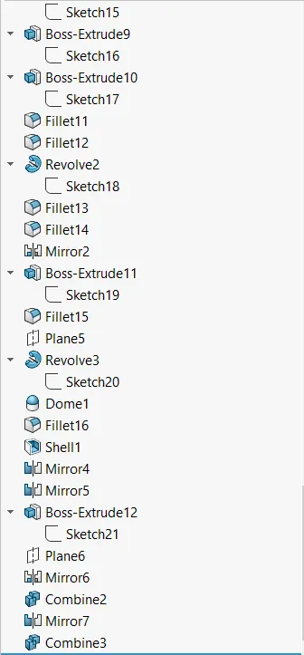
Features:Line,Splines,Circles,3D sketches,Offset,Convert Entities,Projected curves,Surface Loft,Surface Sweep,Surface Extend,Surface Fill,Surface Trim,Knit Surface,Ruled Surface,Combine,Linear Pattern,Fillets,Chamfers.
4. Garage Door
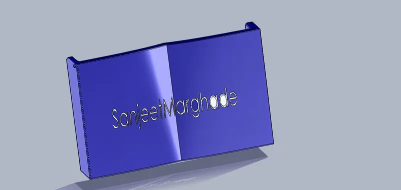
This is a door to the garage of the yatch where vehicles are parked, and prevents water from entering into the garage.
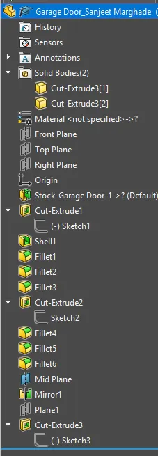
Features:Lines,Circles,Rectangle,Extrude Boss/Base,Mirror,Text Projection,Fillet.
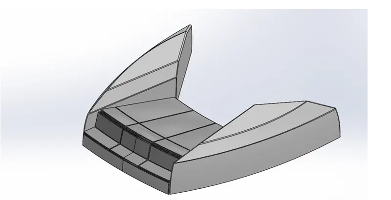
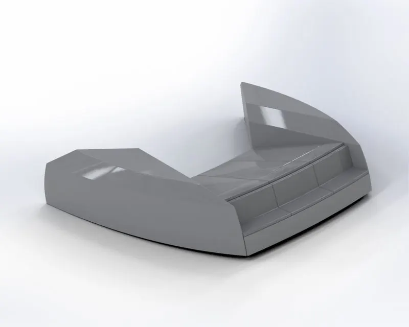
5. Front Seat
A seat situated in the front on the yatch.
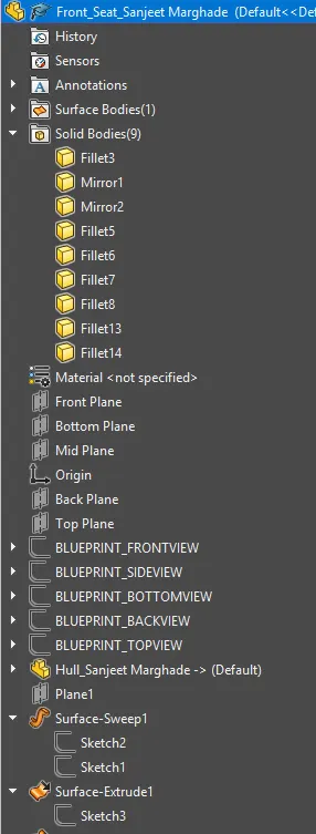
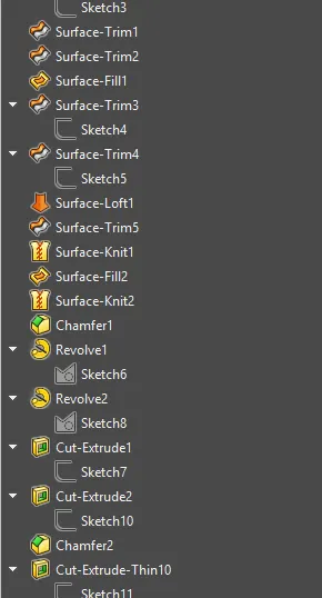
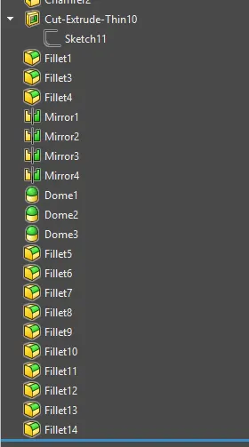
Features:Lines,Splines,Rectangles,Extrude Boss/Base,Cut Extrude,Dome,Mirror,Fillet.
6. Middle Seat
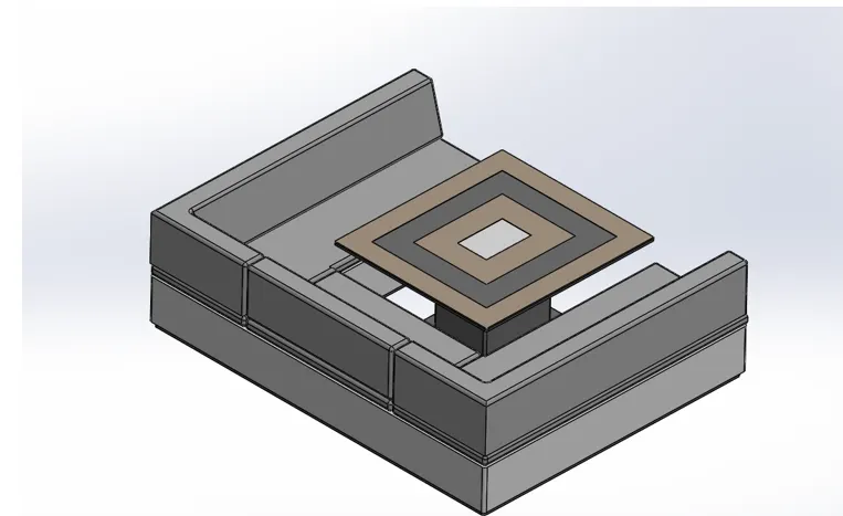
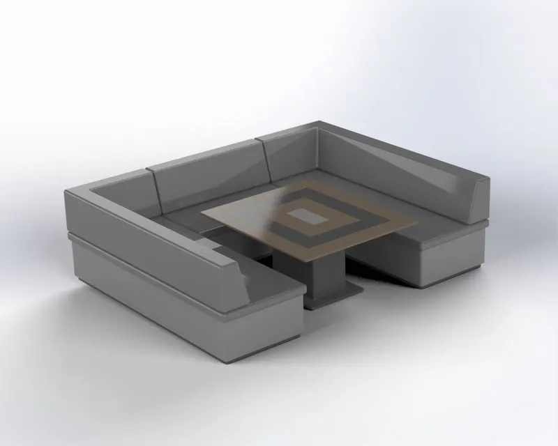
This seat is at the rear of the yatch above the garage
Features:Lines,Rectangles,Extrude Boss/Base,Cut Extrude,DomeMirror,Fillet,Chamfer.
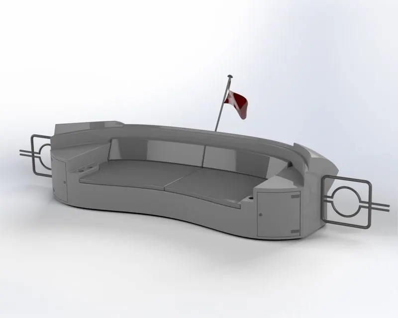
7. Rear Seat
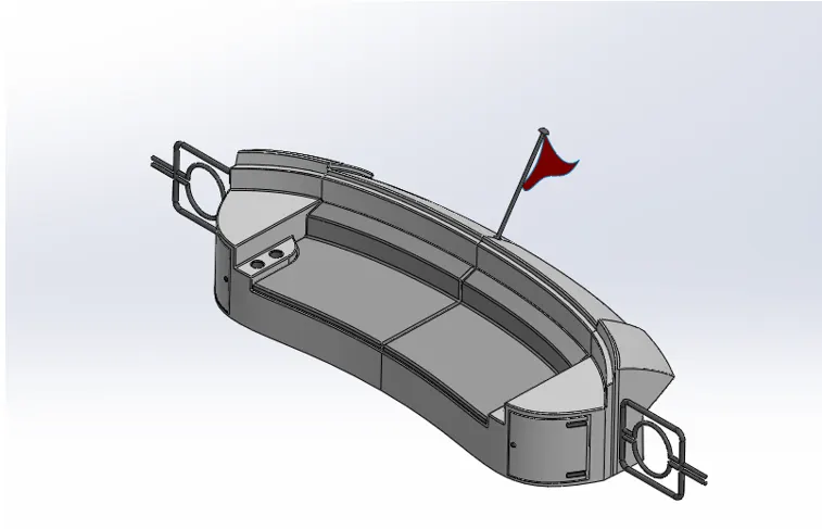
The is also situated at the rear of the yatch above the garage and opposite the middle seat
Features:Lines,Splines,Rectangles,Surface Sweep,Surface Loft,Surface Trim,Surface Offset,Ruled Surface,Surface Knit,Extrude Boss/Base,Cut Extrude,Sweep,Revolve,Mirror,Fillet,Chamfer.
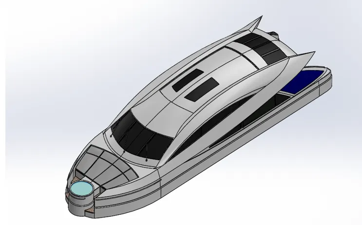
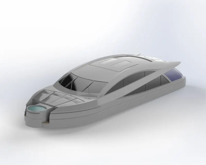
8. Superstructure
A superstructure is an extended construction of any building or platform that rises above the rest of the building or platform in a distinct manner. On a water craft, the superstructure consists of the parts of the ship or boat, that project above the main deck. The size of a watercraft's superstructure can have many implications in the performance of ships and boats, since these structures can alter their structural rigidity, their displacements, and/or stability.
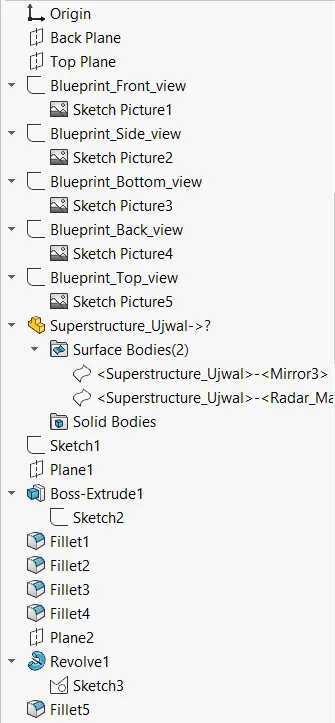
Features:Line,Splines,Circles,3D sketches,Offset,Convert Entities,Projected curvesSurface, LoftSurface ,SweepSurface FillSurface, Trim,Knit Surface,Ruled Surface,Surface Offset,Extrude Boss/Base,Cut Extrude,Sweep,Dome,Fillets,Chamfers.
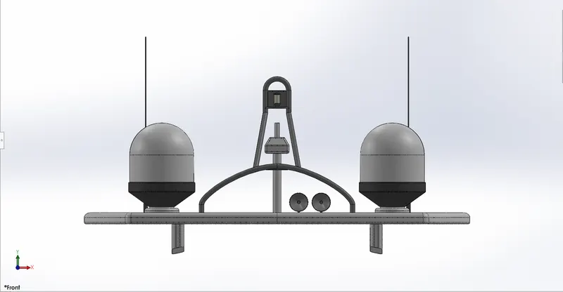
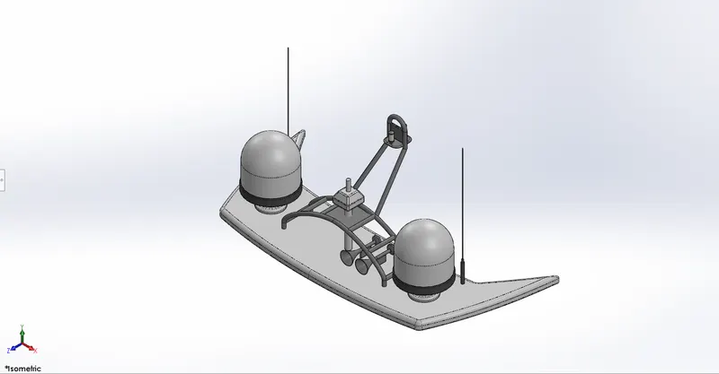
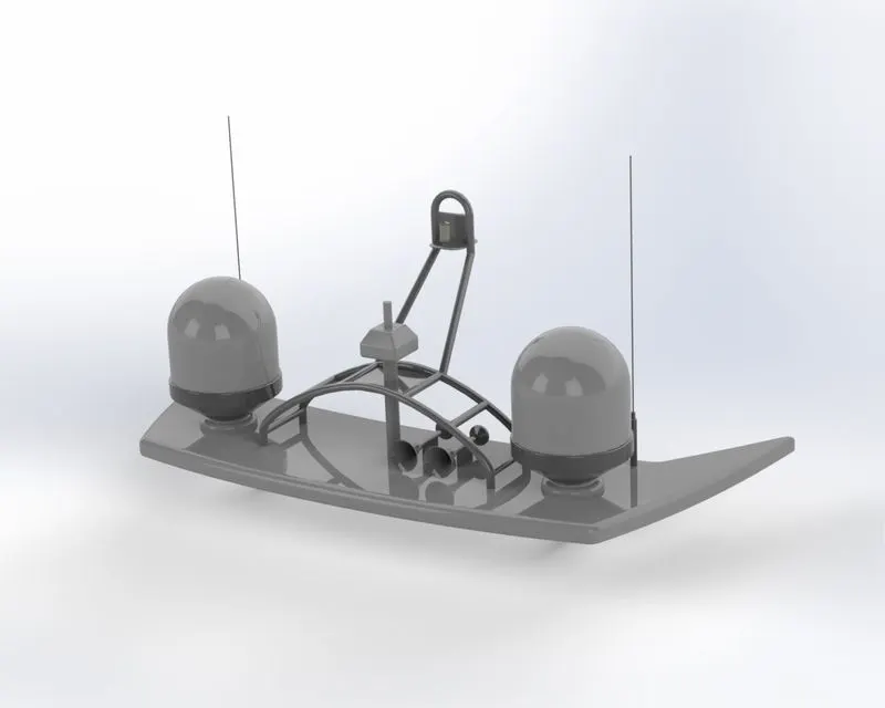
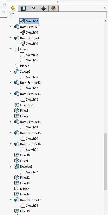
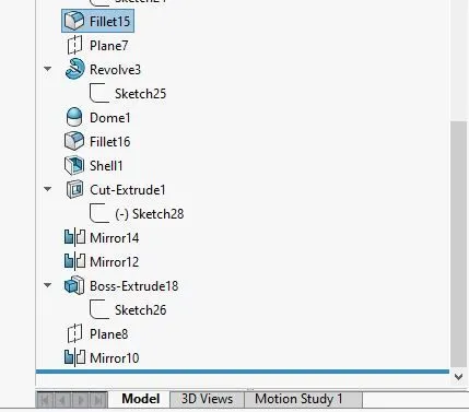
9. Radar Mast
The Mast of a sailing vessel is a tall spar, or an arrangement of spars erected more or less vertically on the centre-line of a ship or boat.
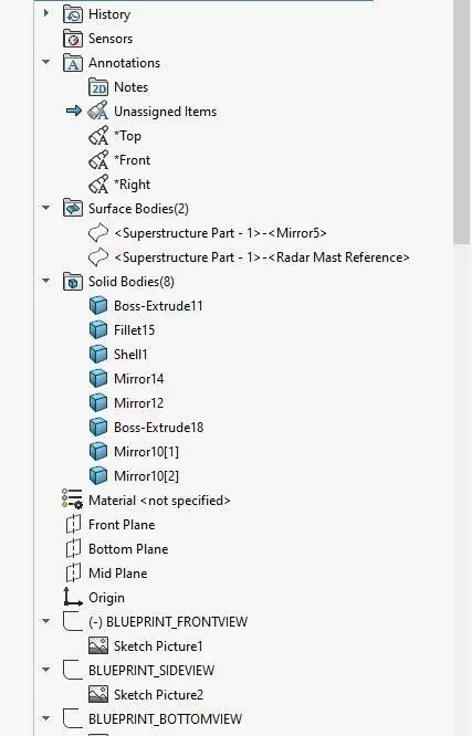
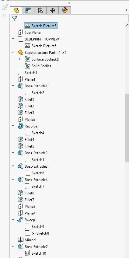
Features:Line,Splines,Circles,3D sketches,Offset,Convert Entities,Projected curvesSurface, LoftSurface ,SweepSurface FillSurface, Trim,Knit Surface,Ruled Surface,Surface Offset,Extrude Boss/Base,Cut Extrude,Sweep,Dome,Fillets,Chamfers.
Creating the Assembly :
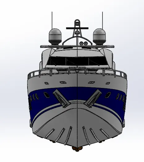
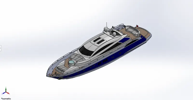
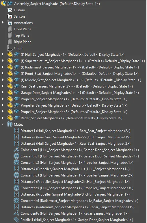
- All these individual parts are then assembled together using the SolidWorks Assembly file.
- First off, the Hull is fixed at the proper location.
- Rest all the parts are then located with respect to this fixed Hull.
- Standard Mates such as Coincident, Tangent, Concentric, Parallel, etc are used to provide appropriate constraints.
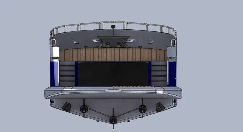
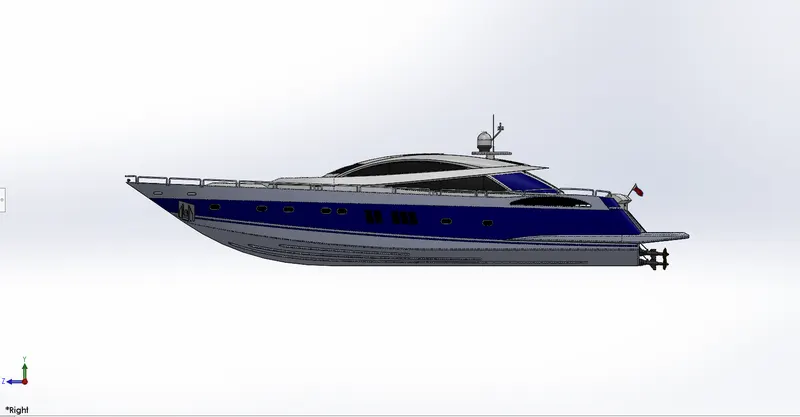
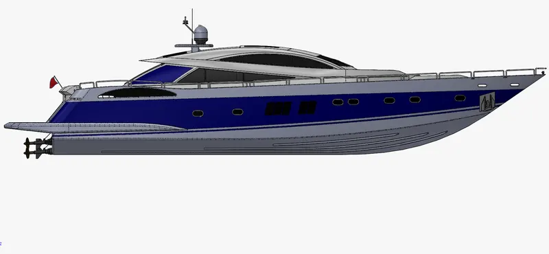
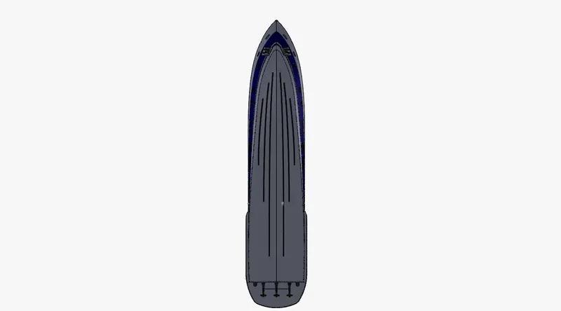
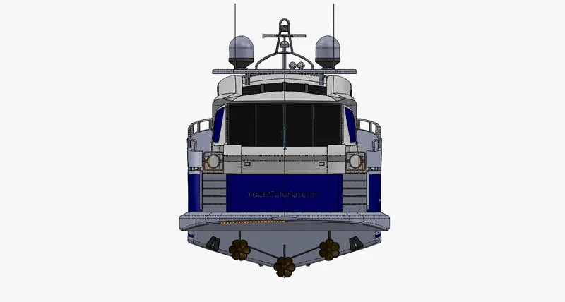
- Shown below are the standard vies of the Assembly -

Rendering :
- Available Decals are added to enhance the outlook of few of the parts.
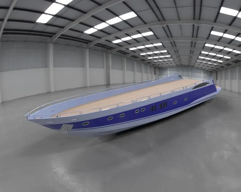
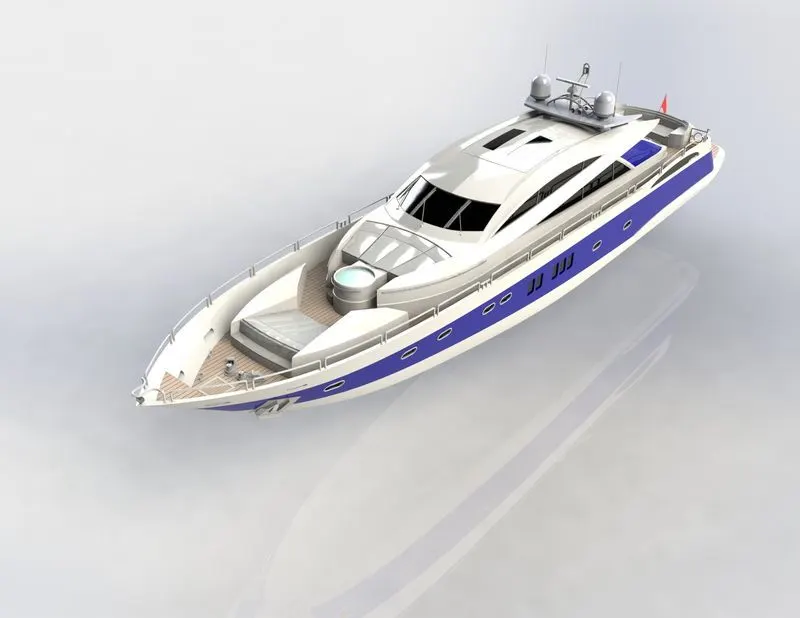
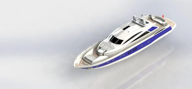
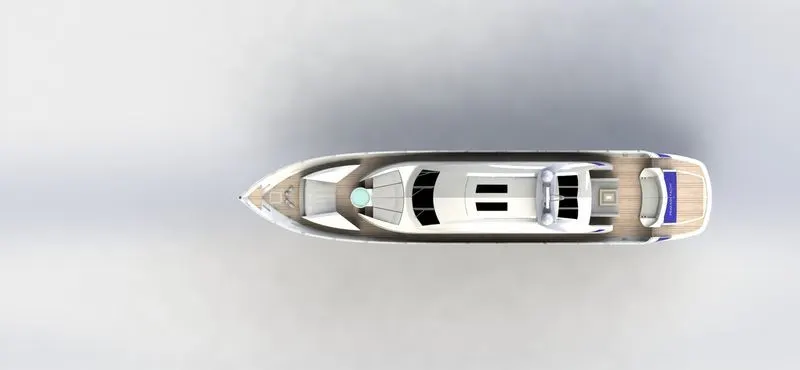
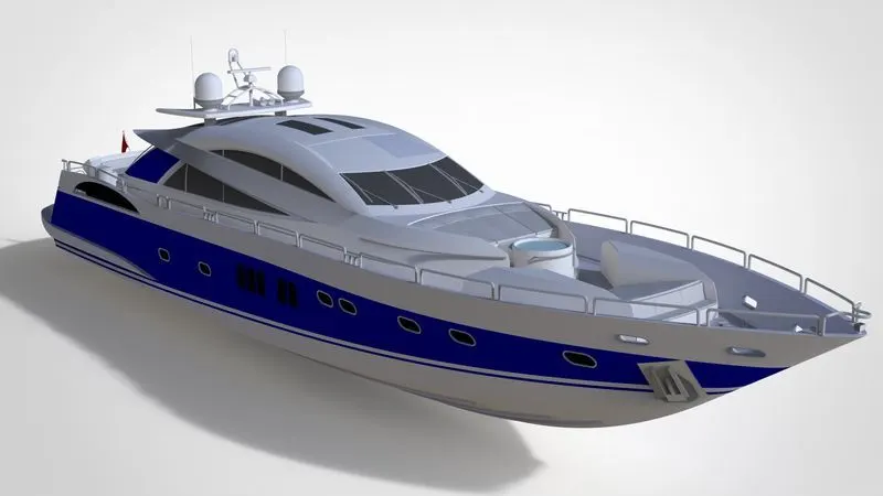
- The Yacht Assembly is rendered using the Add-In SolidWorks Visualize tool provided by SolidWorks.
- Proper Scene is created for the rendering.
- Appropriate Environment is set up for this purpose. Also, a suitable Backplate is chosen out of the library.
- Camera is set up by providing appropriate location.
- The Perspective view is enabled to ensure real-time look.
- Now, after providing suitable appearances the model is rendered.
conclusion:
Thus the Sunseeker Predator Yacht had been successfully modelled and assembled using SolidWorks. Final Rendering is also
carried out using Photoview 360 and Solidworks Visualize.