Final Assembly and rendering images of YACHT
SUNSEEKER PREDATOR YACHT MODEL DESIGNING AND RENDERING
SURESHKUMAR
INTRODUCTION
First we are all should know about the purpose of this project before start the modelling of an American predator yacht. After clear on it we are going to learn about the part modelling and surface modelling using the various commends in solidworks. we need to use the different appearances for various parts to easily identify each parts from a group after finishing the modelling. After finishing all the parts with proper constraints and dimensions we can assemble them using different mate comment. finally, we are going to learn about the rendering of the assembled model using photoview 360 with the help of adding cameras, decals, scene and lights. Not only that, but we can also render it with solidworks visualize software to bring up the realistic image by different plates and environment.
The components which we will learn in this predator yacht are:
- Blueprint setup
- Radar and radar mast
- Propeller
- Hull
- Seats
- Superstructure
OBJECTIVE
- We should learn about the feature commands, sketch tools, geometric constraints, etc. in solidworks.
- To learn how to give the appearance to a face, body, surface or feature based on the quality output.
- Using the blueprint sketch we should know how to draw the 2D sketches with proper dimensions and constraints.
- To get the clear idea about how to use the different mates in assembly modelling.
- We need a clear idea on adding cameras, decals, scene and lights to gets the number of realistic views from assembled model.
- To learn how to render the assembled model using photoview 360 and solidworks visualise software.
DESIGN PROCESS
The design process is an approach for breaking down a large project into manageable chunks. architects, engineers, scientists are use the design process to solve a variety of problems. Use this process to define the steps needed to tackle each projects, and remember to hold to all of your ideas and sketches throughout the process.
 DESIGN APPROACH
There are two types of approach in design procedure. 1. Bottom up approach and 2. Top down approach. Here in this project we have used Bottom-up approach and we get the clear idea by defining these terms.
- Top down approach: In the top-down model, an overview of the system is formulated without going into detail for any part of it. So you can start your work in the assembly and built parts to fit in the assembly. You can use the geometry of one part to help define the other parts or to create machined features that are added only after the parts are assembled.
- Bottom up approach: In this design, you can create parts, insert them into an assembly, and constraint them as required by your design. An advantage of bottom-up design is that, since components are designed independently, their relationships and regeneration behaviour are similar than in top-down design.
MODULES IN SOLIDWORKS
Solidworks extends design applications through full integration with best-in-class solution. And each module has different features and working procedures that will help on your design process. The following modules are explained below.
- Part modules
- Assembly modules
- Surface modules
- Sheet metal modules
- Drawing
- PhotoWorks
Part modelling:
This module produces parts easily and rapidly by creating features such as extrude, revolve, lofts, sweeps, patterns, etc. in solidworks, you can design a part by sketching its components shapes ad defining their size, shape and Inter-relationships.
Assembly modelling:
Assembly design gives a user the ability to design with user controlled associability. Solidworks builds these individual parts and sub-assemblies into an assembly in a hierarchical manner. This is based on relationships defined by the constraints.
Surface modelling:
For designing dies, castings or injections molds, surface modelling capability is important. Solidworks surface module can create complex models from free form shapes. You can create complex surfaces using lofts and sweeps with guide curve, drag-handles for easy control ad innovative surface feature.
Sheet metal design:
Sheet metal parts are generally used as enclosures for components or to provide support to other components. We can design a sheet metal part on its own without any references to the parts it will enclose. The main feature of sheet metal is its ability to be formed and shaped by a number of processes.
Drawing:
A 2d drawing view is a representation of a 3d cad part or assembly that is placed on drawing sheet. The drawing views represent the shape of the object when viewed from various standard directions such as front, side, top and so on.
PhotoWorks:
Photoview 360 is a solidworks add-in that produce photo-realistic rendering of solidworks models. The rendered image incorporates the appearances, lighting, scene and decals included with the model.
First let’s see what basic sketch entities, features and constraints are in solidworks to create the parts.
SKETCH ENTITIES:
It helps user to create sketch required to feature creation. So we can use the specific number of sketch entities to create a 2D base sketch for parts development. Also the sketch tools are available to modify and edit the sketch for required shape.
Line: we can use the line entities to draw a straight line to connect the two points with few constraints along with proper dimensions.
Circle: we can use the circle entities to draw a circle based on center point that may be an origin point, vertex or anything.
Spline: we can use the spline entities to draw a special type of curves and critical shaped curves by connecting two or more points.
Rectangle: it’s closed sketch entities to draw a squares as well as rectangles from an origin, vertex, edges, or face center.
Arc: it is a portion of circle to connect the two points by drag the cursor based on center point or starting point.
Offset: add sketch entities by offsetting edges, faces, curves or sketch entities with a specific distance.
Trim: trim or extend the sketch entities used to deletes a sketch entities or a sketch entity to be coincident to another.
Sketch pattern: add sketch entities by linear or circular pattern based on direction and number of instance.
Mirror: we can mirror the selected entities about a centerline.
Move/copy/rotate: we can move, copy, rotate, scale and stretch a sketch entity by defining the direction or base point.
FEATURES:
It helps user to create 3D sketch from 2D sketch by using required features in comment manager. also we can add or remove the materials from existing part model to satisfy the requirement. Before activate the feature comment we should verify that the 2D sketches are in fully defined sketch with proper dimensions and constraints.
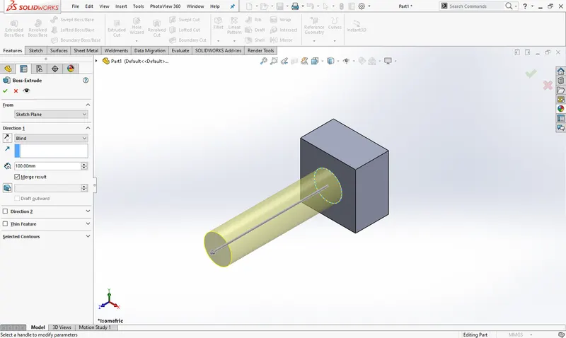
Extrude: we can add or remove the materials by specifying the directions and start point. At the same time user can use draft and thin feature to change the shape of model.
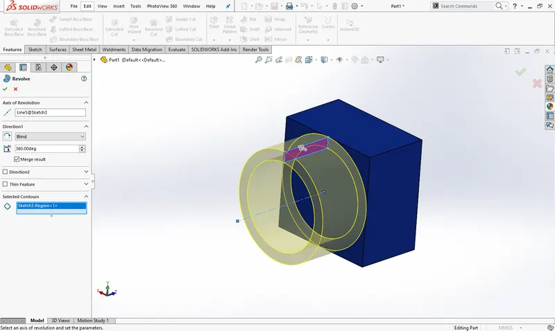
 Revolve: it is same as extrude to add or remove the materials while give direction except specifying the axis of revolution to achieve the revolve feature. Thin feature is also here in revolve.
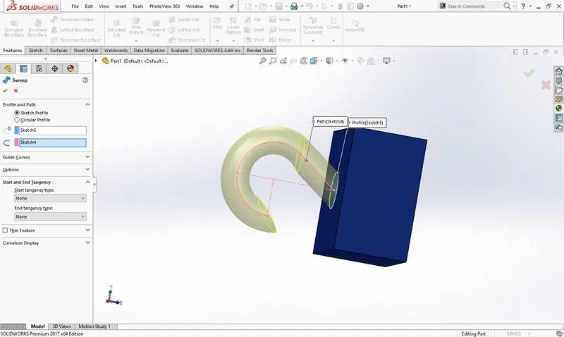
 Swept: it is used to sweep a closed profile along an open or closed guide path to create a solid part. We can develop the complex solid model based on guide path which gives the direction to base profile.
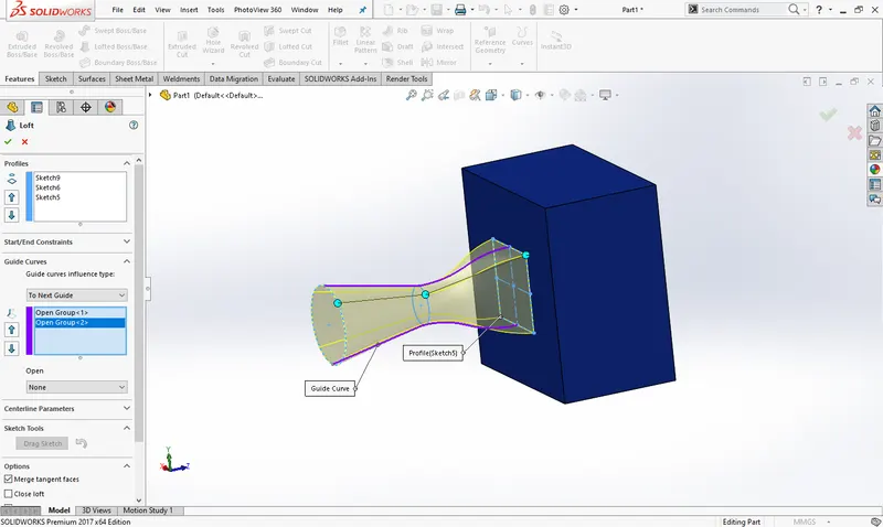
 Loft: it is used to create a solid model between two or more closed profile whether using an open guide path or without guide path. Thin feature also is there to change the shape of model and we can use the start/end constraints to bring up the smooth surface finished solid model.
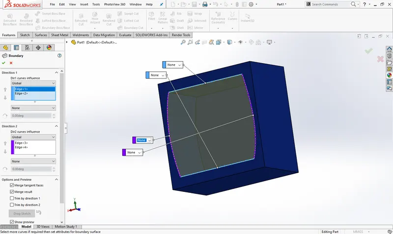
 Boundary: add or remove the material between profiles in two directions to create the solid model. But there is no guide path to perform this boundary feature.
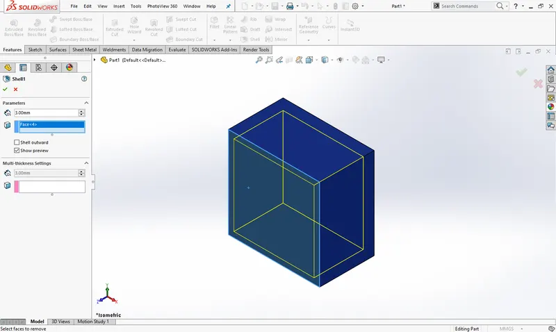
 Shell: we can remove the material from a solid body to create a thin walled feature. In shell feature the selected faces will delete from body otherwise the shell feature lies inside the body if you are not select the any face.
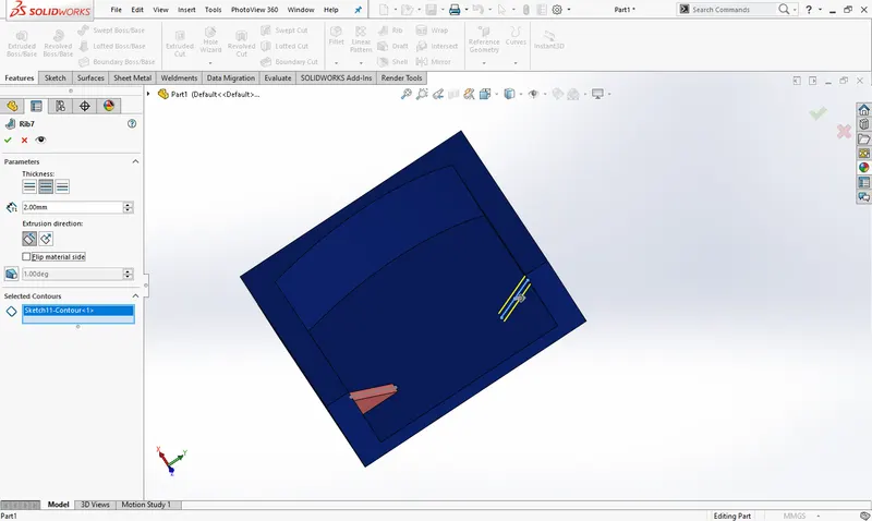
 Rib: it is used to adds the thin walled support to the solid body. Its purpose is to sustain or support the stability of solid body.
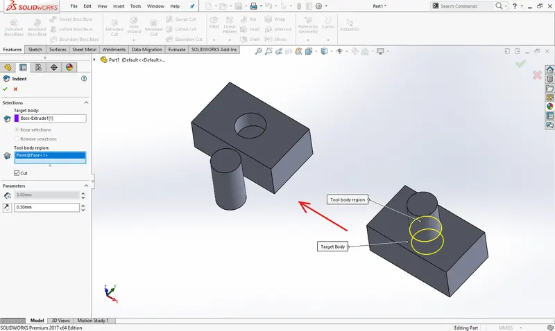
 Indent: the indent feature creates an offset pocket or protrusion features on a target body that exactly matches the contour of a selected tool body.
 SURFACES:
Surface models are a type of 3D models with no thickness. This models are widely used in industries like automobiles, aerospace, medicals, and so on. In part modelling, you have created models with mass properties but surface models do not have thickness. The surfaces are generally used to create models of complex shapes.
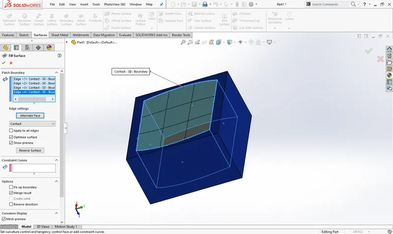
Filled surface: it creates a surface patch within a boundaries defining from existing model edges, curves or sketches. Also you can create a complicated surface patch using constraint curves.
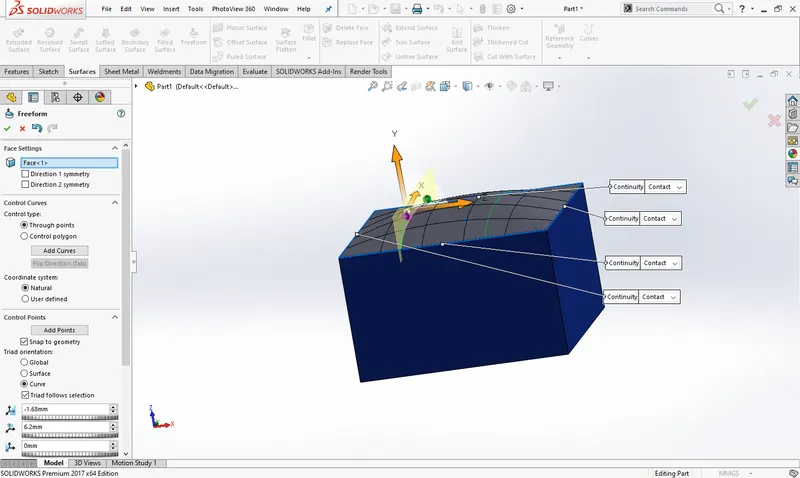
 Freeform: it adds the deformed surface to a planer or non-planer face by pushing or pulling on control points. You can control the deformed surface using control curves and control points where you want.
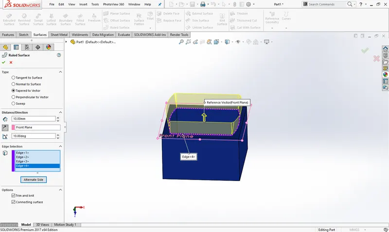
 Ruled surface: it creates surfaces that extend out in a specified direction from selected edges. There are different types you have to use to control that extended surface.
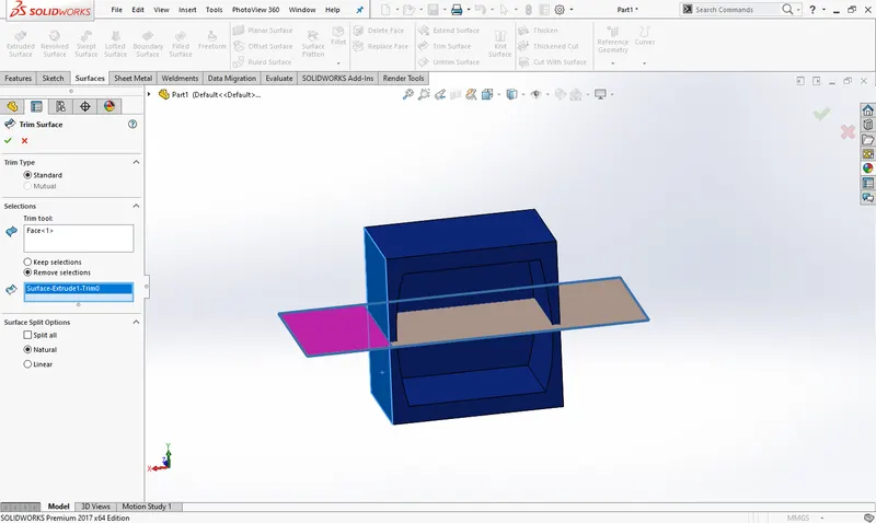
 Trim surface: it removes a surface from target body where one surface intersects with another surface, a plane or a sketch.
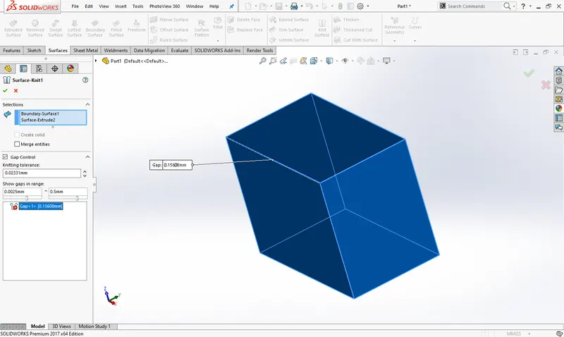
 Knit surface: it combines the two or more adjacent, non-intersecting surfaces together with kitting tolerance. And you have merge entities to merge excess faces, edges, and vertices.
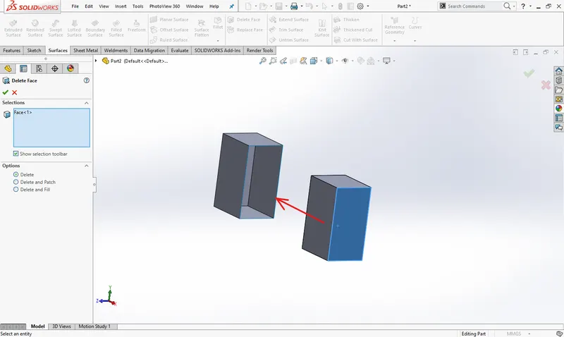
 Delete face: it deletes faces from the solid body to create a surfaces or deletes faces from the surface bodies. When we face the problem with delete face there is many options you have to rectify if possible.
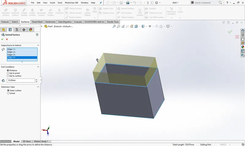
 Extend surface: it extends the edge, multiple edges of the face on the surface based on end condition and extension type. And using the end condition and extension type we can easily handle that.
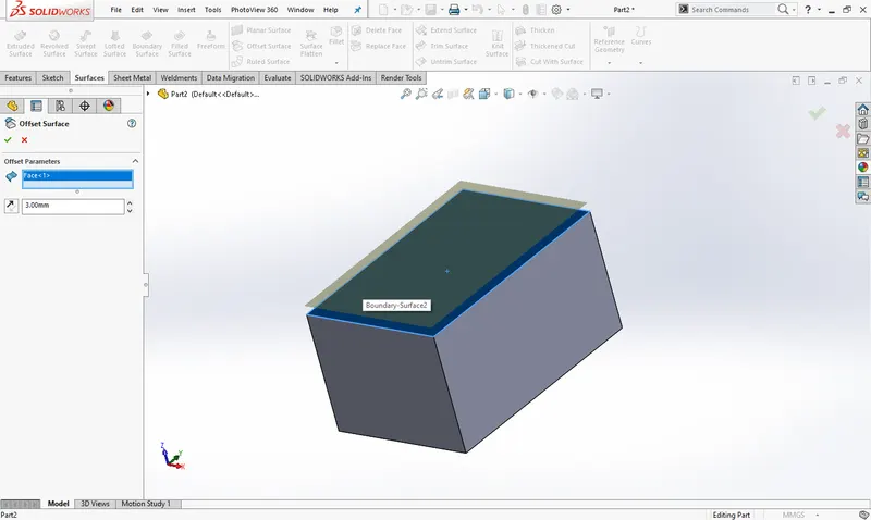
 Offset surface: it creates surfaces from one or more continuous surfaces and faces with distance. It may be use in assembly modelling when you use it from base part to design other related parts.
 Mate: Mate feature creates geometric relationship between assembly parts. When we add mates, it defines the allowable direction of linear or rotational motion of component within its degree of freedom. Otherwise the assembly parts are fixed with base part and it will float along with base part. This feature includes as below:
- Coincident mate: it used to mate the two bodies coincident to make a contact with each other. After this mate the one part turns to get only the linear motion based on where we apply this mate like on face, corner or vertex.
- Concentric mate: two circular faces are mate concentric by its axis or circular edges. This mate allows the rotational motion about the axis.
- Tangent mate: we can mate the one cylindrical face with other planer face at 90° angle. After this mate one body can move over another body with contact point.
- Width mate: A width mate constrains a tab between two planar faces. The components align so that the tab is mated between the faces of the groove. The tab can translate along the center plane of the groove and rotate about an axis normal to the center plane.
DESIGN METHODOLOGY:
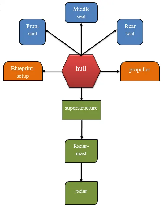
Now we have completed discussion of how the features work under solid works. Let us see the application of the features in the predator yacht that we have built. We are going to discuss part by part as shown in the flowchart.
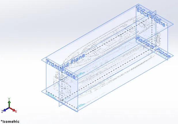
Blueprint setup: first import the 2D drawing sketch for sunseeker predator yacht into solidworks part file through sketch tool and sketch picture. We had number of orientation sketch views for design. So imported one by one with appropriate position as well as scaling which are most important has to be done as well. In solidworks port file there only three primary planes. So you can add more planes if you want.
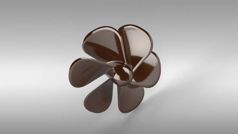
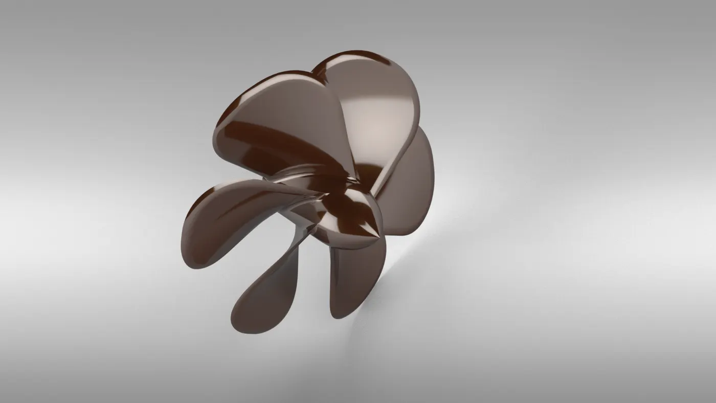
Propeller: it is a mechanical device that rotates to push against air or water. Propeller is an aerodynamic device which converts rotational energy into propulsive force creating thrust which is approximately perpendicular to its plane of rotation. Propellers have two or more blades spaced evenly around the hub. Its design looks like a flower outer.
Features used to create the hull:
- Sketch entities
- Revolve
- Plane
- Loft
- Cut extrude
- Circular pattern
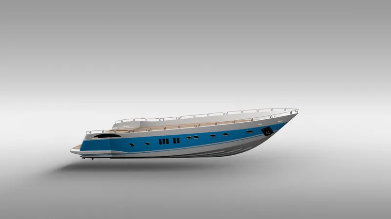
 Hull: A hull is the watertight body of a ship, boat, or flying boat. The hull may open at the top, or it may be fully or partially covered with a deck. The deck may be a deckhouse and other superstructures, such as a funnel, derrick, or mast. The line where the hull meets the water surface is called the waterline. Let’s see their designing process because it’s interesting to start using blueprint sketch with surface modelling. And the entire hull design will contain both the solid and surface modelling half to half.
Features used to create the hull:
- Blueprint sketch
- Sketch entities
- Surface loft
- Surface trim
- Surface knit
- Planes
- Sweep
- Boss-extrude
- Cut extrude
- Revolve
- Linear pattern
- Delete face
- Fillet
- Chamfer
- Mirror
 Garage door: I have designed a garage on back of the hull for parking the user’s vehicles. So this garage door is for production of things which is presenting inside of the garage. It will move ups and down with specific angle which is defined in assembly file using angle mate.
Features used to create the hull:
- Sketch entities
- Cut extrude
- Fillet
- Shell
- Delete face
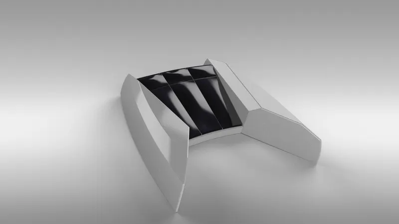
 Front seat: we are all know why the seats are used there and its purpose and it is located on front of the hull deck surface. Its 3D view looks like a birds wing and you can see this beautiful world in front of you from there. The design for this was started from surface modelling with the help of inserted deck surface from hull design. Finally, its turn out into solid model and mirror it about mid plane.
Features used to create the hull:
- Blueprint sketch
- Sketch entities
- Surface sweep
- Surface trim
- Surface knit
- Cut extrude
- Revolve
- Fillet
- Dome
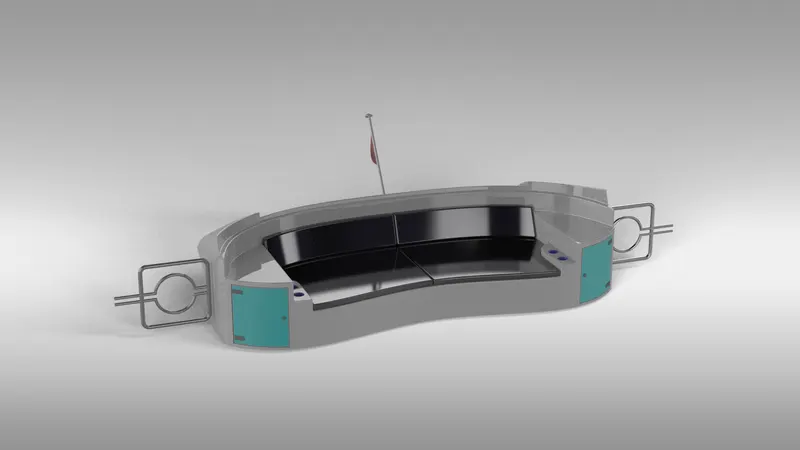
 Rear seat: you can sit in this seat and relax. Also there will be some lockers for you to keep your personal things. And this design was a little hard to get done compared to other seats design. I started this design from surface modelling and developed through planes, feature comments, 3D-sketch.
Features used to create the hull:
- Blueprint sketch
- Surface sweep
- Surface extend
- Surface extrude
- Surface trim
- Surface knit
- Boss-extrude
- Planes
- Fillet
- Sweep
- Surface offset
- Mirror
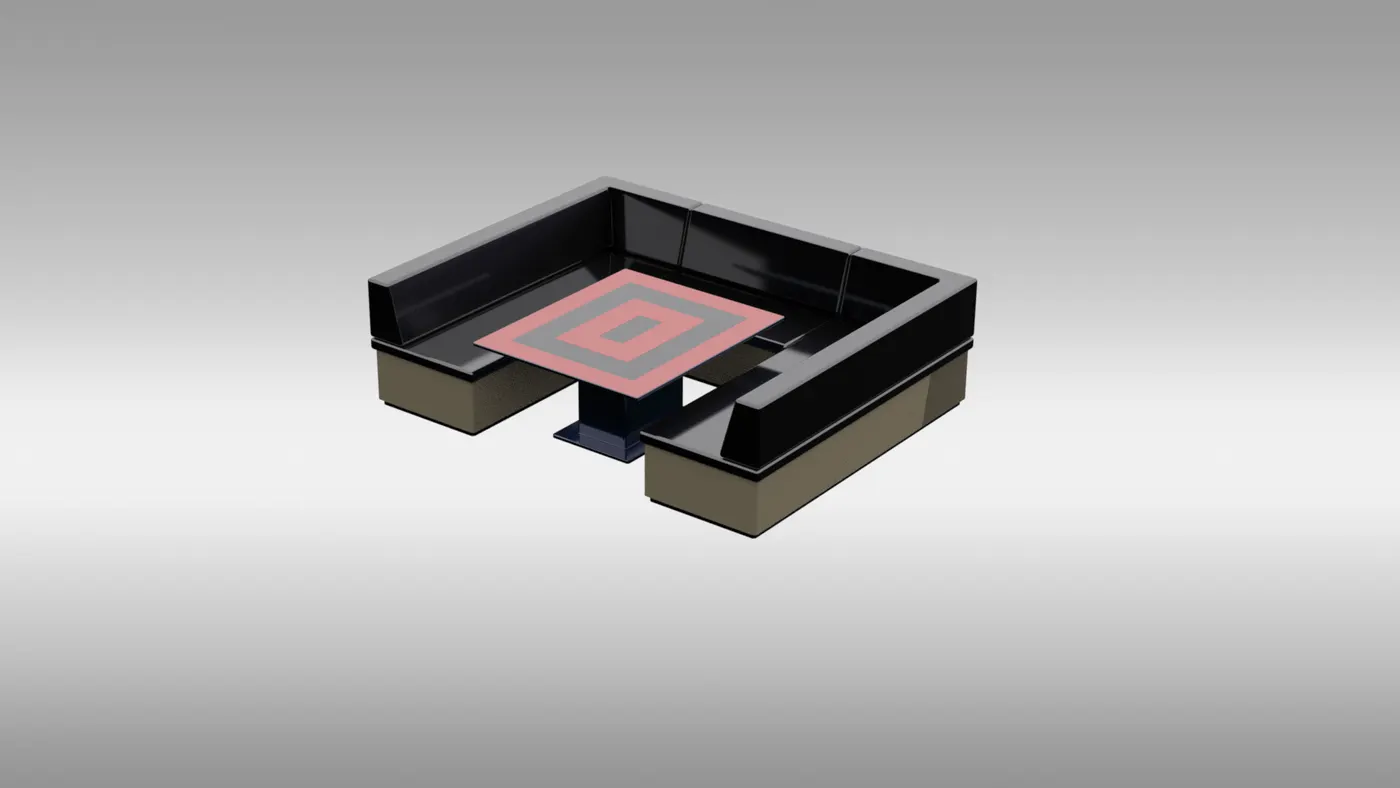
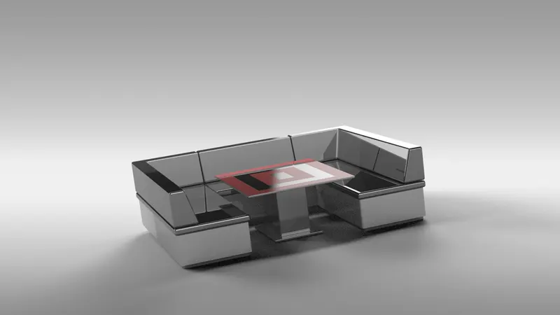
 Middle seat: this can be used as a dining table and will be located in middle of the deck as well as behind the superstructure. Its design is simple to proceed because there are no critical parts in it to design. Using the deck surface from hull this part model was started. During assembly modelling this start will use to reduce the number of mates.
Features used to create the hull:
- Blueprint sketch
- Sketch entities
- Boss-extrude
- Fillet
- Chamfer
- Mirror
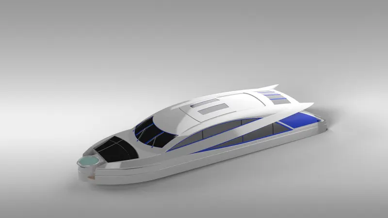
 Superstructure: A superstructure is an extended construction of the predator yacht that rises above the rest of the deck surface in a distinct manner. The superstructure is mostly designed in fashion as well. This is because it is the most easily visible part of the ship, in fact it is the identification of the ship, and so the designers try to provide it with the identity that is unique. I had been developing the entire design of this superstructure using blueprint setup.
Features used to create the hull:
- Blueprint sketch
- Sketch entities
- Surface loft
- Surface sweep
- Surface extend
- Ruled surface
- Surface extrude
- Surface trim
- Surface knit
- Boss-extrude
- Cut extrude
- Sweep
- Split line
- Mirror
 Radar mast: A radar mast is the pole that rises vertically from the predator yacht and holds up the sails and radar on it. It is used to support the sails, yards, radar and radio equipment, etc. Using the offset surface from superstructure I started its designing as well as I followed that blueprint setup.
Features used to create the hull:
- Blueprint sketch
- Sketch entities
- Boss-extrude
- Revolve
- Planes
- Sweep
- Fillet
- Mirror
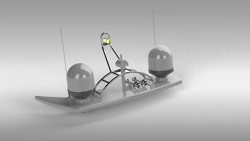 Radar: The radar is defining as an electromagnetic sensor used for detecting, locating, tracking, and recognizing objects of various kinds at considerable distances. Radar works by emitting a high frequency radio wave, and then listening for any return signals that get bounced back. The designing of radar is look like very simple here but in professional its interior design can be very difficult.
Features used to create the hull:
- Blueprint sketch
- Sketch entities
- Boss-extrude
- Cut extrude
- Fillet
- Sketch pattern
- Mirror
 ASSEMBLY:
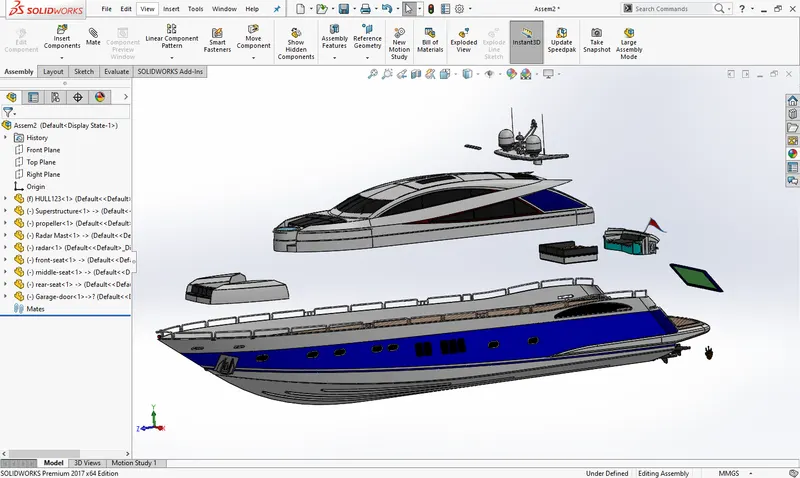
All the parts were modelled and imported into solidworks assembly file to assemble them. In assembly modelling the mate feature is most commonly used to locate and relate the parts with another one. Hull is main component which is inserted first and I will be fixed automatically. The other components were inserted one by one into the assembly file. By using the planes for reference and giving the mate feature once the part gets fixed then it floats with the main part which part were inserted first. Some parts were modified during assembly to make it perfect according to requirement.
 DECALS:
A decal is something called a “transfer”, and it consists of a picture, image, pattern, or design that’s printed on metal body. We have added decals on deck surface, stair steps, garage deck, hatch, rear deck, front deck, and Jacuzzi stair step of yacht. It gives nice appearance to the sunseeker predator yacht.
 RENDERING:
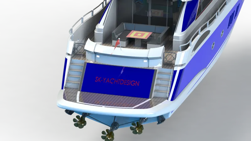
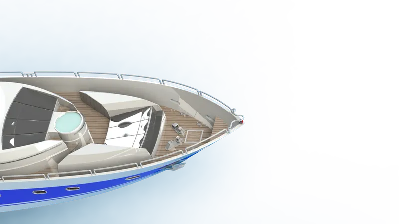
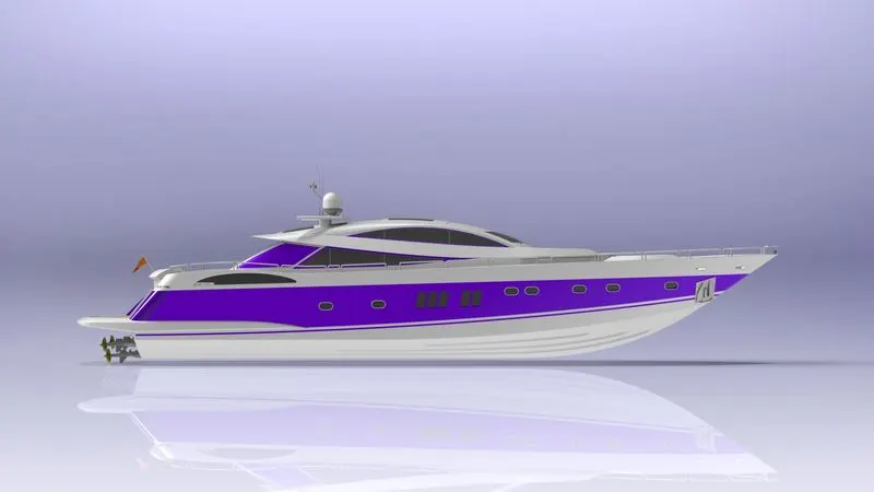
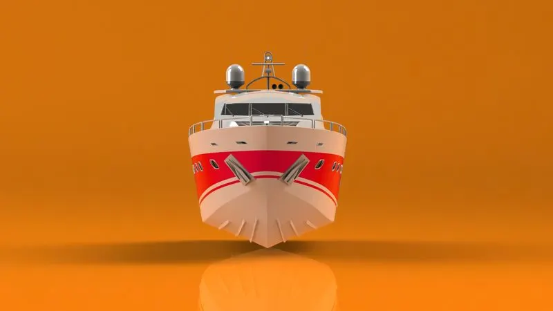
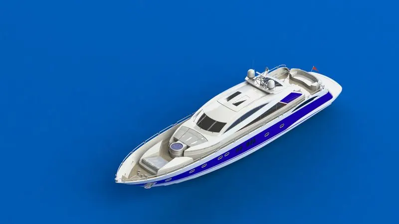
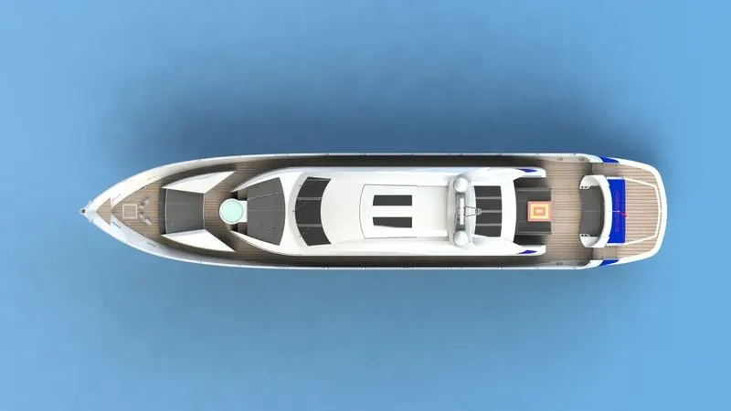
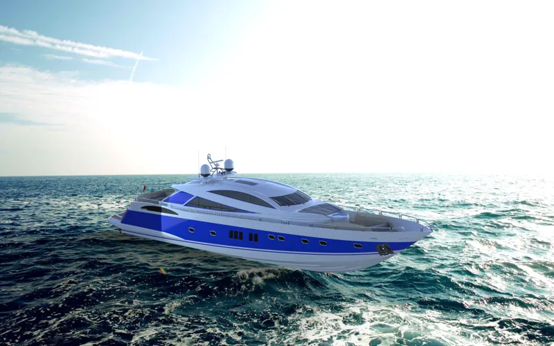
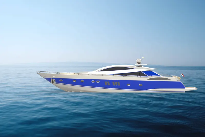
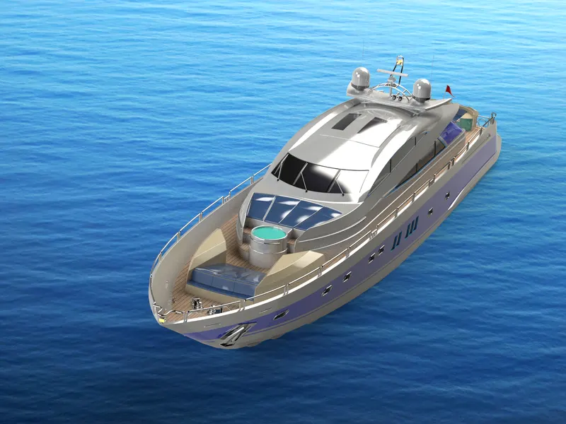
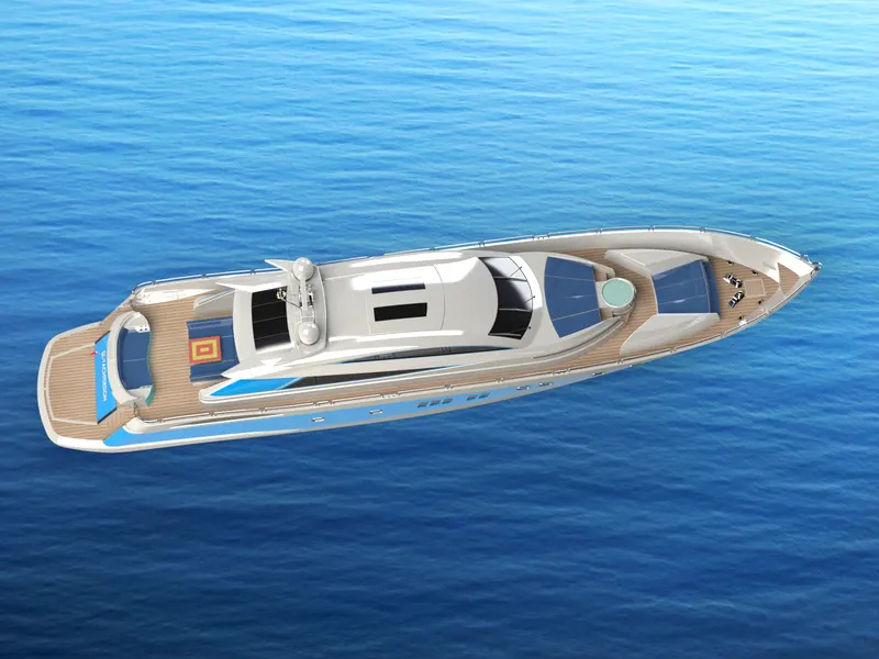
The term rendering comes from the graphic world where a rendering is an artistic drawing of what a new structure would look like. In computer aided design, a rendering is a particular view of a realistic image. By doing rendering of sunseeker predator yacht we get the idea that how it will look into the environment. This rendering is done in the “solidworks visualize” software as well as “photoview 360”. By using photoview 360 we can add various camera views to the model, we can set various angles, direction, and can set appropriate distance to get the perfect camera view. In rendering we change colour of sunseeker predator yacht parts, background images, brightness, rotation and various setting of sunseeker predator yacht. Including the resolution and setting number of passes we get more detail visuals of sunseeker predator yacht.
Rendering on photoview 360
 Rendering on solidworks visualize:
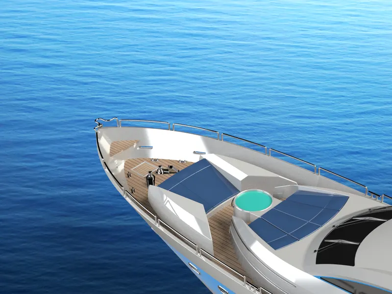
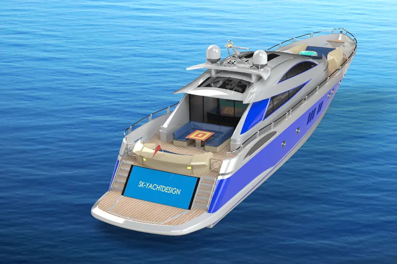 Conclusion: Sunseeker predator yacht designed has conformed to the projects aims and objective. Sunseeker predator yacht has been successfully designed and assembled to optimise the marine system. The appropriate components for the predator yacht and their purpose were researched from the references. In addition to component research a broader knowledge was gained about submarines, ships and boadts, this information proved essential for gaining a better understanding of buoyant force and working principle. Finally, a design process was implemented in a chronological order starting with empathise define ideate prototype and test.