Photo Realistic Rendering of CHOPPER bike
MODELLING AND RENDERING OF AMERICAN CHOPPER ON SOLIDWORKS
SURESHKUMAR
INTRODUCTION
First we are all should know about the purpose of this project before start the modelling of an American chopper. After clear on it we are going to learn about the part modelling and surface modelling using the various commends in solidworks. we need to use the different appearances for various parts to easily identify each parts from a group after finishing the modelling. After finishing all the parts with proper constraints and dimensions we can assemble them using different mate comment. finally, we are going to learn about the rendering of the assembled model using photoview 360 with the help of adding cameras, decals, scene and lights. Not only that, but we can also render it with solidworks visualize software to bring up the realistic image by different plates and environment.
The components which we will learn in chopper are:
- Front and rear fender
- Kickstand
- Petal
- Oil tank and fuel tank
- Chain and transmission belt
- Front and rear wheel with rim sprocket and calliper
- Chassis
- Engine
OBJECTIVE
- We should learn about the feature commands, sketch tools, geometric constraints, etc. in solidworks.
- To learn how to give the appearance to a face, body, surface or feature based on the quality output.
- Using the blueprint sketch we should know how to draw the 2D sketches with proper dimensions and constraints.
- To get the clear idea about how to use the different mates in assembly modelling.
- We need a clear idea on adding cameras, decals, scene and lights to gets the number of realistic views from assembled model.
- To learn how to render the assembled model using photoview 360 and solidworks visualise software.
DESIGN PROCESS
The design process is an approach for breaking down a large project into manageable chunks. architects, engineers, scientists are use the design process to solve a variety of problems. Use this process to define the steps needed to tackle each projects, and remember to hold to all of your ideas and sketches throughout the process.

DESIGN APPROACH
There are two types of approach in design procedure. 1. Bottom up approach and 2. Top down approach. Here in this project we have used Bottom-up approach and we get clear idea by defining these terms.
- Top down approach: In the top-down model, an overview of the system is formulated without going into detail for any part of it. So you can start your work in the assembly and built parts to fit in the assembly. You can use the geometry of one part to help define the other parts or to create machined features that are added only after the parts are assembled.
- Bottom up approach: In this design, you can create parts, insert them into an assembly, and constraint them as required by your design. An advantage of bottom-up design is that, since components are designed independently, their relationships and regeneration behaviour are similar than in top-down design.
MODULES IN SOLIDWORKS
Solidworks extends design applications through full integration with best-in-class solution. And each module has different features and working procedures that will help on your design process. The following modules are explained below.
- Part modules
- Assembly modules
- Surface modules
- Sheet metal modules
- Drawing
- PhotoWorks
Part modelling:
This module produces parts easily and rapidly by creating features such as extrude, revolve, lofts, sweeps, patterns, etc. in solidworks, you can design a part by sketching its components shapes ad defining their size, shape and Inter-relationships.
Assembly modelling:
Assembly design gives a user the ability to design with user controlled associability. Solidworks builds these individual parts and sub-assemblies into an assembly in a hierarchical manner. This is based on relationships defined by the constraints.
Surface modelling:
For designing dies, castings or injections molds, surface modelling capability is important. Solidworks surface module can create complex models from free form shapes. You can create complex surfaces using lofts and sweeps with guide curve, drag-handles for easy control ad innovative surface feature.
Sheet metal design:
Sheet metal parts are generally used as enclosures for components or to provide support to other components. We can design a sheet metal part on its own without any references to the parts it will enclose. The main feature of sheet metal is its ability to be formed and shaped by a number of processes.
Drawing:
A 2d drawing view is a representation of a 3d cad part or assembly that is placed on drawing sheet. The drawing views represent the shape of the object when viewed from various standard directions such as front, side, top and so on.
PhotoWorks:
Photoview 360 is a solidworks add-in that produce photo-realistic rendering of solidworks models. The rendered image incorporates the appearances, lighting, scene and decals included with the model.
DESIGN METHODOLOGY:
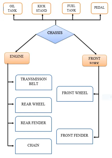
Let’s see what are the features and properties used in the entire model to design different parts:
- Extrude
- Revolve
- Fillet
- Mirror
- Circular pattern
- Reference plane
- Shell
- Combine
- Projection curve
- Mate
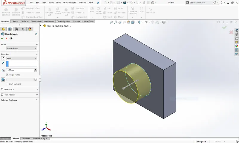
Extrude: Extrude is a basic feature in solidworks to bring up a complete solid body from any shape of 2D sketch which is completely fully defined with closed entity. After exit from the 2D sketch, in command manager the extrude feature will appear. So when we are going extrude the sketch the popup window opens in property manager. Based on the need there are many options existing in extrude feature (direction1 and direction 2, draft, thin features)
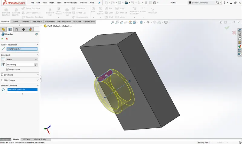
Revolve: It is almost similar with extrude except use the direction to control the solid body. The revolve feature only support for closed sketch along with axis to revolve. Without axis of revolution you can’t use this feature.
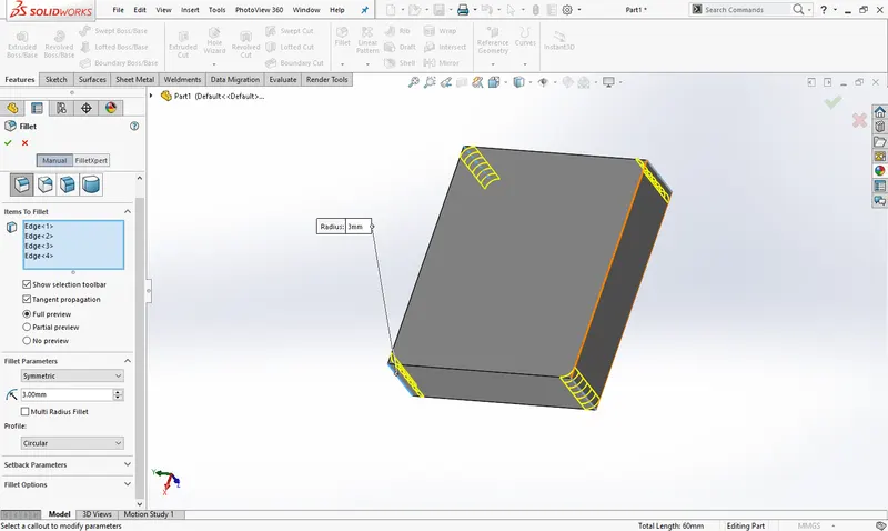
Fillet: It is always important in all the part modelling to remove the sharp edges in corner. It will give smooth round surface finish from part corners and vertices.
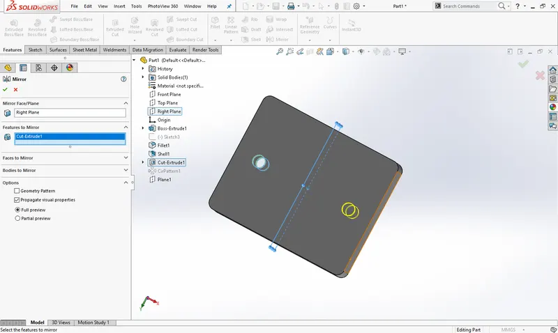
Mirror: It is used to mirror the solid body or any feature like extrude cut, patterns, etc. By using mirror face/plane. After mirror we can modify that when you deselect the merge result from property manager.
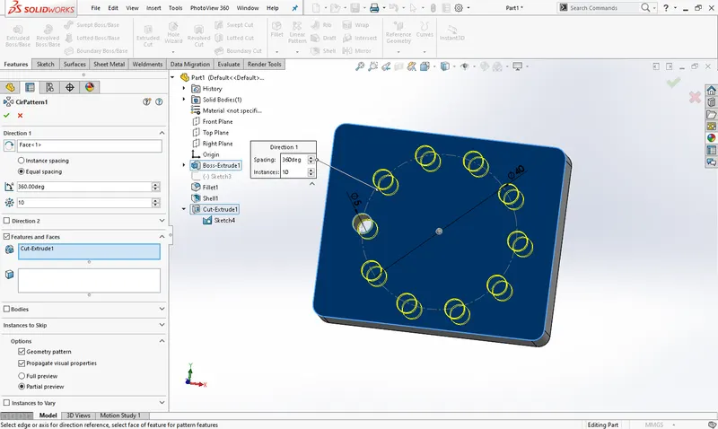
Circular pattern: Basically the patterns are minimizing the number of step you want on create multiple feature as same from single feature. Based on the needs the patterns are varied. In circular pattern you should give the direction as well as angle to position number of instance.
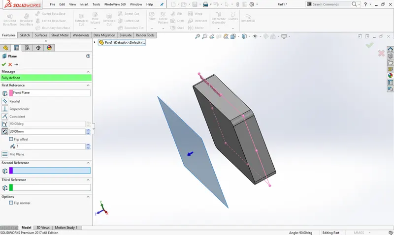
Reference plane: Reference geometry gives the important features like reference plane, axis, coordinate system and points to reduce the difficulties during design process. When you going to sketch away from origin or primary planes you need to use this. If you are going to use it, then you must concentrate on geometric constrains.
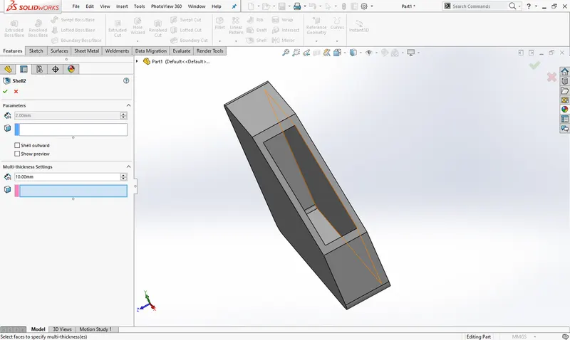
Shell: Shell feature is used to remove the material from entire part that make a part hollow space with specific wall thickness. We can get the closed shell by without selecting any face instead the open shell form by selecting number of faces we need.
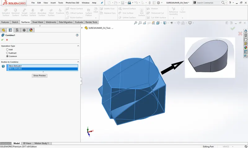
Combine: In this feature we have few things like add, subtract and common. If we need a common body from two different bodies, then we can use it. Also we use add to combine the two solid bodies or use subtract to remove the part from main body which we select.
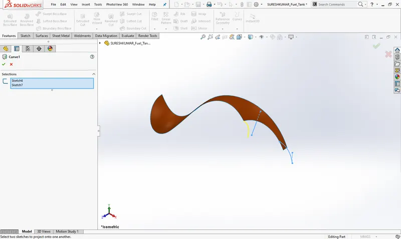
Projection curve: If we are going to design a complicated surface model like car body or any plastic components we need 3D sketch. But it is difficult to use because it will take time. So we can sketch some different entities then project it as 3D sketch.
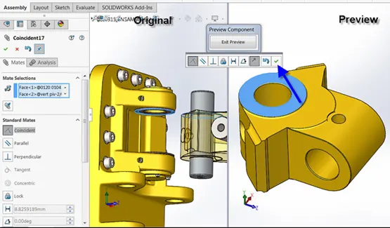
Mate:Mate feature creates geometric relationship between assembly parts. When we add mates, it defines the allowable direction of linear or rotational motion of component within its degree of freedom. Otherwise the assembly parts are fixed with base part and it will float along with base part.
This feature includes as below:
- Coincident mate: it used to mate the two bodies coincident to make a contact with each other. After this mate the one part turns to get only the linear motion based on where we apply this mate like on face, corner or vertex.
- Concentric mate: two circular faces are mate concentric by its axis or circular edges. This mate allows the rotational motion about the axis.
- Tangent mate: we can mate the one cylindrical face with other planer face at 90° angle. After this mate one body can move over another body with contact point.
- Width mate: A width mate constrains a tab between two planar faces. The components align so that the tab is mated between the faces of the groove. The tab can translate along the center plane of the groove and rotate about an axis normal to the center plane.
Now we have completed discussion of how the features work under solid works. Let us see the application of the features in the chopper that we have built. We are going to discuss part by part as shown in the flowchart.
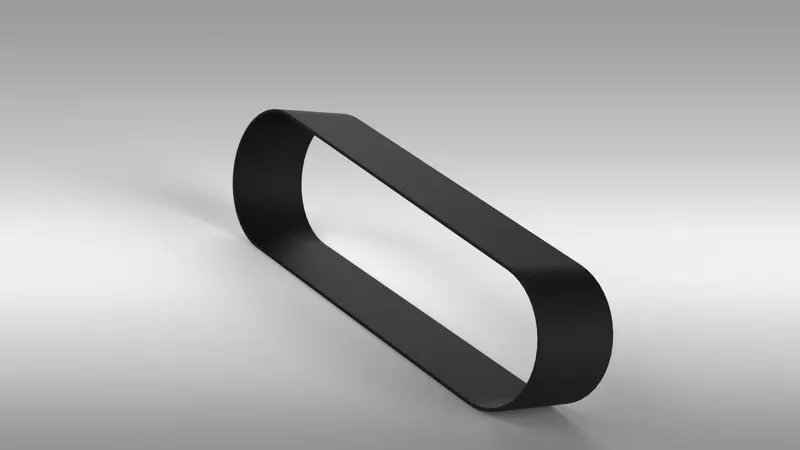
Transmission Belt: Transmission belt is located at the round surface of the pulleys. To transmit the power with help of pulleys. The commonly used material for this is rubber. It is a solid body in which transmission belt are filleted and the appearance given is matte rubber.
Features used to create the transmission belt:
- Sketch
- Extrude
- Offset
- Fillet
- Appearance
Kick Stand: While designing kickstand first we have created sketch based on an additional plane, the part created by using loft feature and dome has been applied on the both sides of kickstand. Then at the bottom part to rest the kickstand, the flat surface has created by using sketch. We have used extruded cut for an assembly purpose. After the part has been created we applied fillets to sharp the edges.
Features used to create the kickstand:
- Sketch
- Ellipse
- Splines
- Loft
- Cut extrude
- Boss extrude
- Split
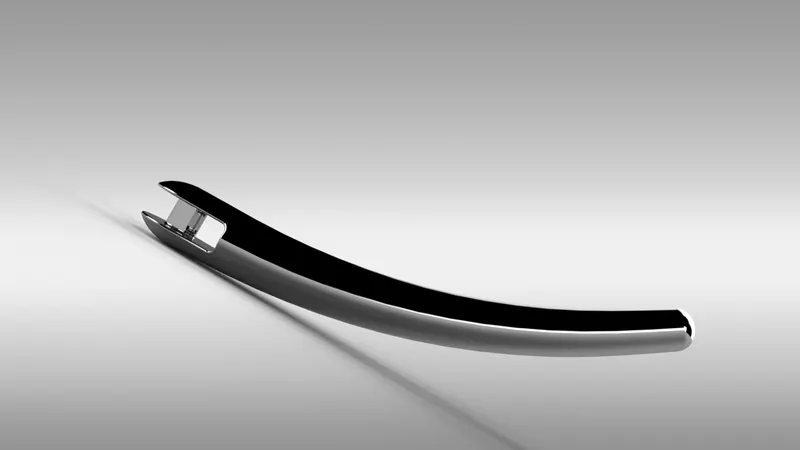
Front Fender: Here we revolved the sketch using an axis and created half curved solid body. Some sharp edges designed on the both sides of fender by using the split tool the material is removed. The edges of the fender are filleted.
Features used to create the Front fender:
- Sketch
- 3-point arc
- Offset
- Extend
- Trim
- Revolve
- Spline
- Fillet
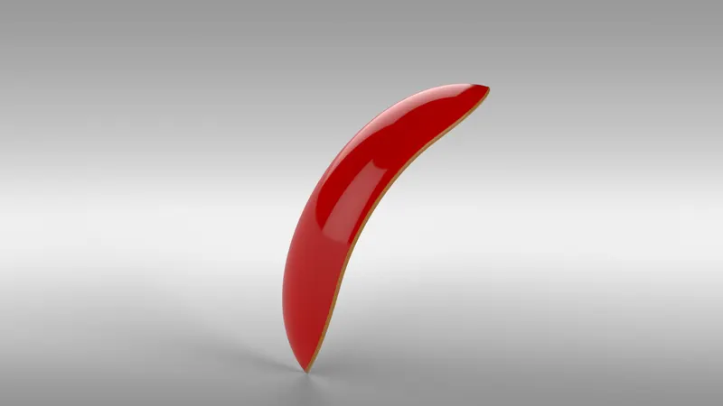
Rear Fender: Same procedure is used to make rear fender as it was used in front fender. Only the difference between the two are sizes as according to the size of the tire. The front and rear fender are made of metal and appearance given is sienna colour which is bright orange texture.
Features used to create the Rear fender:
- Sketch
- 3-point arc
- Extend
- Trim
- Revolve
- Spline
- Fillet
- Shell
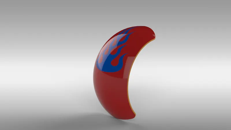
Oil Tank: The base of the oil tank is sketched on the top plane and extruded above to attain the structure of oil tank and another sketch is added on the mid plane it is then extruded and then combined together and at the end a shell function is used to make part hollow from inside. Fillet is applied on the outer edges to make it round. The appearance given to the oil tank is sienna colour and the edges filleted are given white paint.
Features used to create the Oil tank:
- Lines
- 3-point arc
- Boss extrude
- Combine
- Fillet
- Shell
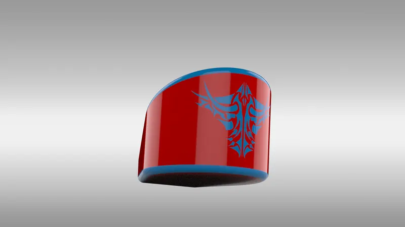
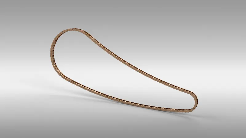
Chain: To create chain first we need to draw the sketch using arcs and lines, the line must be tangent to the arc. Then we draw the sketch of blocks and pins and extrude it, then the pins and blocks were pattern along the path and by calculating the number of pins and blocks. When the whole front side chain pattern created then we can mirror to the mid plane and both side of the blocks has been created.
Features used to create the Chain:
- Circles
- 3-point arc
- Slot
- Block
- Fillet
- Curve pattern
- Mirror
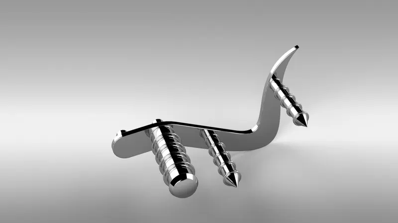
Pedal: A pedal is a strong rigid body and used to rest the foot while riding bike. The various features are used to create the pedal are splines, fillets, dome, chamfer and linear pattern. The appearance given to the pedal is chrome metal.
Features used to create the Pedal:
- Sketch
- Lines
- Circles
- Fillet
- Revolve
- Dome
- Chamfer
- Linear pattern
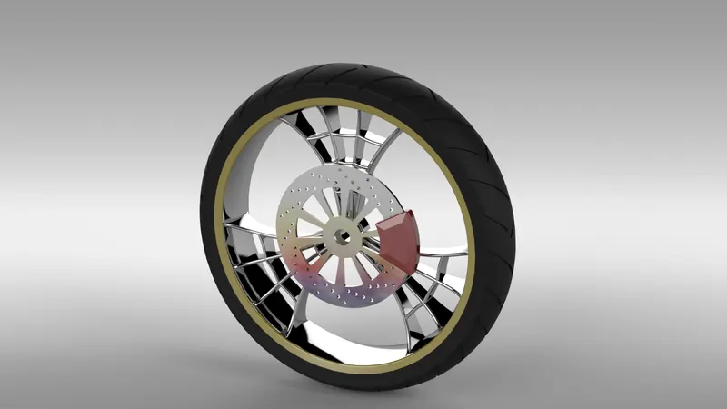
Front Wheel: Front wheel is having larger diameter than the rear wheel to manage impact better than the rear. Front wheel experiences greatest force during braking. First, the rim was created by revolve feature and the spider webbed spokes were created by using splines and offsetting them. Then the spider webbed spokes were pattern to the rim. On rim rotor and calliper were modelled. The tire was modelled using revolve and threads were applied then the appearance given to the wheel.
Features used to create the Front wheel:
- Sketch
- Lines
- 3-point arc
- Sketch fillet
- Revolve
- Spline
- Extend
- Trim
- Cut extrude
- Offset
- Revolve cut
- Circular pattern
- Chamfer
- Fillet
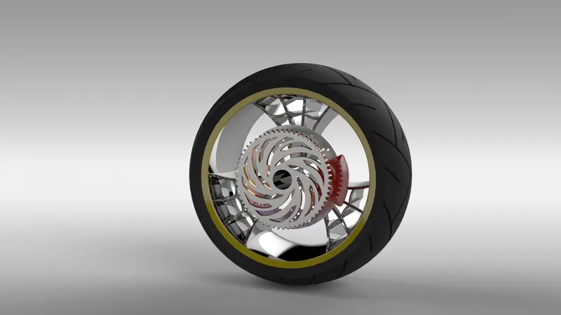
Rear Wheel: The rear tire is primarily used for accelerating the vehicle and move it forward. It is wider than the front wheel. It gives stability to the vehicle. The steps were followed same like front wheel and appearance given is also same only the component added here sprocket to link the chain.
Features used to create the Rear wheel:
- Sketch
- Lines
- 3-point arc
- Sketch fillet
- Revolve
- Spline
- Extend
- Trim
- Extrude cut
- Offset
- Revolve cut
- Circular pattern
- Chamfer
- Fillet
Front Fork: Front fork attach the whole chassis and the front wheel. It is typically made with triple clamps. It is also used to give suspension to the whole bike and front wheel includes parts front fork, handle bars, head lights, break and clutch levers. First the half portion of the front fork has been created and the whole body is mirrored about the plane. Projected curves were used to model the handles and the cables. The handles of the front fork were given grips.
Features used to create the Front fork:
- Sketch
- Lines
- Revolve
- Circle
- Fillets
- Linear pattern
- Spline
- Extrude cut
- Dome
- Curve
- Sweep
- Plane
- Mirror
- Combine
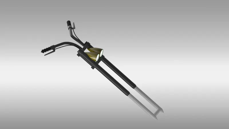
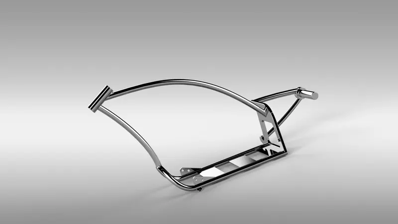
Chassis: The chassis is the main frame of the chopper. It holds all the components such as front fork, pedals, kickstand, oil tank, engine, gas tank and rear wheel. It supports all the components and supports to the bike. The modelling of chassis starts with using chopper image for reference. It uses features such as extruded boss, splines, and revolving parts, making mirror and sweep. At the end whole part created by using fillet and it gives nice appearance to the chassis and the sharp edges gets round. The appearance given to the chassis.
Features used to create the Chassis:
- Blueprint sketch
- Splines
- Curves
- Mirror
- Boss extrude
- Extrude cut
- Chamfer
- Dome
- Split
- Revolve
- Combine
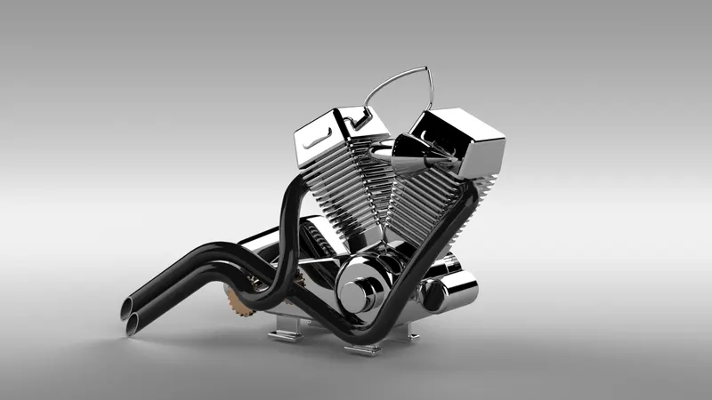
Engine: The main part of the bike is engine. It is also called as heart of the bike. It provides necessary power to drive the bike. A picture is taken for the reference for modelling. The engine consists of parts like crank shaft, transmission pulleys and motor. The upper part of crank shaft the cooling fins were located. The air filters were drawn using spline and the exhaust system is also made with splines and projected curves and sweep feature. The edges of the engine were filleted.
Features used to create the Engine:
- Blueprint sketch
- Lines
- Circles
- Boss extrude
- Fillet
- Revolve
- Dome
- Circular pattern
- Chamfer
- Linear pattern
- Mirror
- Cut extrude
- Combine
- Composite curve
- Split
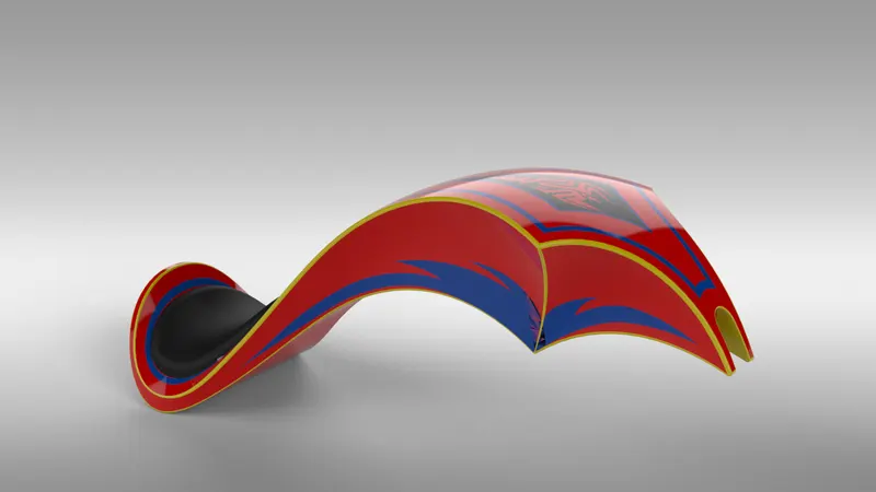
Fuel Tank: This part is mainly made with splines and sweep feature. The half part of the gas tank first created and then it is then mirrored about the plane. The two separated parts were made single part by using knit feature. The gas tank covers the oil tank and engine, and also it acts shield to prevent the heat from the engine. The seat was modelled on the top of the gas tank. The fillets were added to the edges of the gas tank. At the last shell feature were added to make it hollow from inside.
Features used to create the Gas tank:
- Blueprint sketch
- Spline
- Surface sweep
- Surface trim
- Surface boundary
- Surface loft
- Curve
- Mirror
- Surface knit
- Surface extrudes
- Fillet
- Extrude cut
- Shell
ASSEMBLY:
All the parts were modelled and imported into solidworks assembly file to assemble them. In assembly modelling the mate feature is most commonly used to locate and relate the parts with another one. Hull is main component which is inserted first and I will be fixed automatically. The other components were inserted one by one into the assembly file. By using the planes for reference and giving the mate feature once the part gets fixed then it floats with the main part which part were inserted first. Some parts were modified during assembly to make it perfect according to requirement.
DECALS:
A decal is something called a “transfer”, and it consists of a picture, image, pattern, or design that’s printed on metal body. We have added decals on gas tank, rear fender and oil tank of chopper. It gives nice appearance to the chopper.
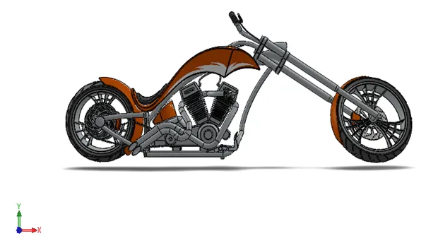
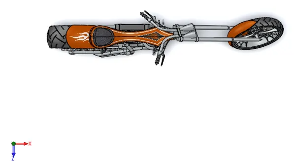
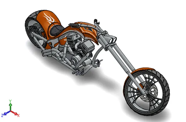
RENDERING:
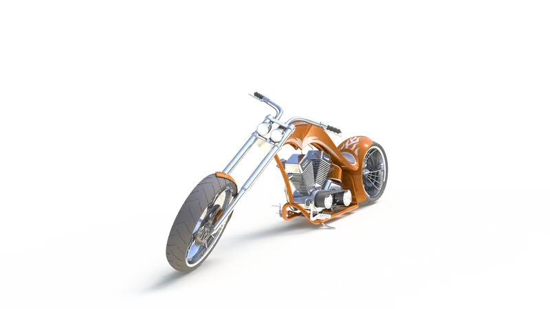
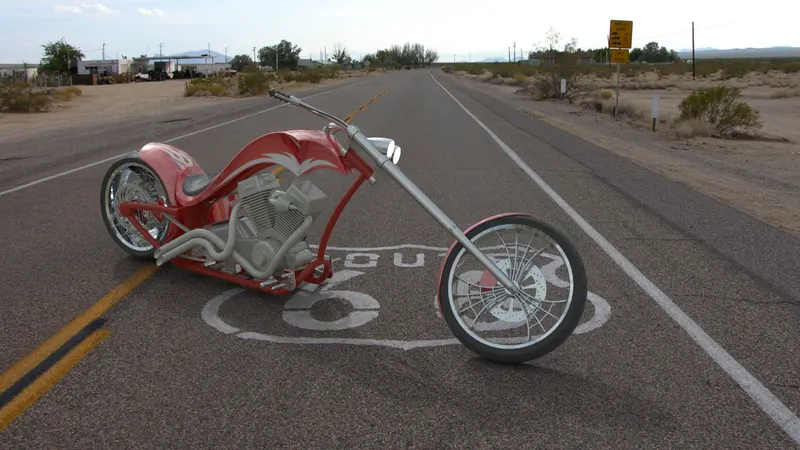
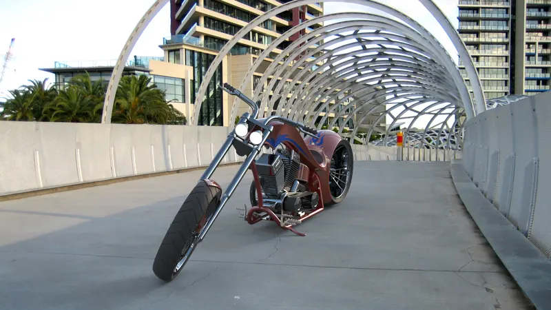
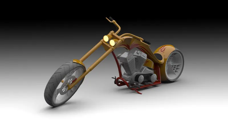
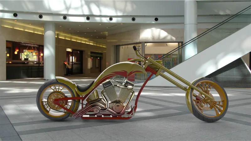
The term rendering comes from the graphic world where a rendering is an artistic drawing of what a new structure would look like. In computer aided design, a rendering is a particular view of a realistic image. By doing rendering of chopper we get the idea that how it will look into the environment. This rendering is done in the “solidworks visualize” software. By using photoview 360 we can add various camera views to the model, we can set various angles, direction, and can set appropriate distance to get the perfect camera view. In rendering we change colour of chopper parts, background images, brightness, rotation and various setting of chopper. Including the resolution and setting number of passes we get more detail visuals of chopper.
PHOTOVIEW 360:
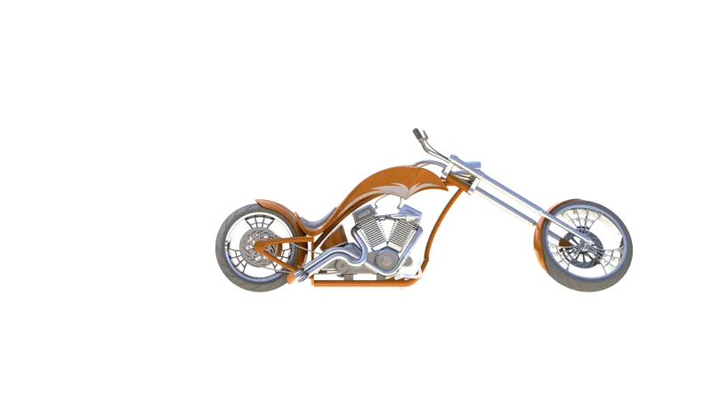
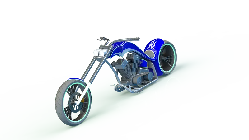
SOLIDWORKS VISUALIZE:
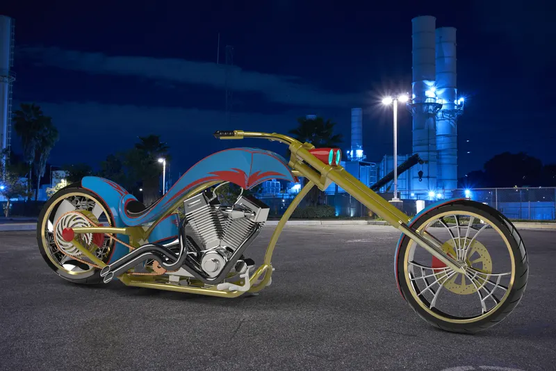
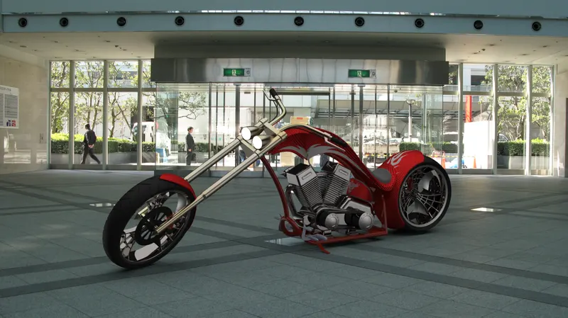
Conclusion: American chopper bike designed has conformed to the projects aims and objective. American chopper bike has been successfully designed and assembled to optimise the automobile field. The appropriate components for the chopper bike and their purpose were researched from the references. In addition to component research a broader knowledge was gained about automobile field, this information proved essential for gaining a better understanding of mechanical parts motions. Finally, a design process was implemented in a chronological order starting with empathise define ideate prototype and test.