Flow over an airfoil
AIM:
The purpose of this analysis is to find out and compare the lift and drag force over an airfoil for different angle of attack using flow simulation.
INTRODUCTION:
Computational fluid dynamics (CFD) is a branch of fluid mechanics that uses numerical analysis and data structures to analyse and solve problems that involve fluid flows. Here solidworks flow simulation is an intuitive computational fluid dynamics (CFD) solution embedded within solidworks 3D CAD that enables you to quickly and easily simulate liquid and gas flows through and around your designs to calculate product performance and capabilities. Velocity is the main parameter to run this flow simulation process and mess as well.
An airfoil is the cross-sectional shape of an object whose motion through a gas is capable of generating significant lift, such as a wing, a sail, or the blades of propeller, rotor, or turbine. So using this airfoil we can pre-determine the lift and drag force for different angle of attack in solidworks flow simulation. Because we are all know how this forces are playing important role in aerospace, maritime, and electricity power plant (thermal, wind, hydraulic, etc.)
THEORY:
As an airfoil cuts through the relative wind or a solid body moving through a fluid an aerodynamic force is produced. This force can be broken down into two components, lift and drag. The component of this force perpendicular to the relative freestream velocity is called lift. The component parallel to the relative freestream velocity is called drag. An airfoil is a streamlined shape that is capable of generating significantly more lift than drag. Most foil shapes require a positive angle of attack to generate lift, but cambered airfoils can generate lift at zero angle of attack.
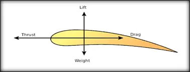
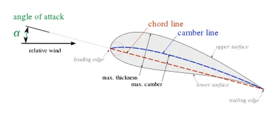
The angle of attack is the angle between the chord line and the relative wind. For any given wing, an increase in angle of attack leads to an increase in the coefficient of lift. To understand airfoil performance at high angles of attack, one must first consider the airflow at just about any angle of attack. When an airfoil passes through an airstream, the particles of air right next to the skin of the airfoil are pulled along at the same speed of the airfoil. As you get further away from the skin of the airfoil, the particles are less apt to "grab on" to the wing and at a certain distance they do not "grab on" at all. This layer of air, the particles that grab on to the wing completely to those that don't, is known as the boundary layer.
And that lift and drag forces just keeps changing according to an angle of attack and the graph below explains to you how it will changes. Lift force will drop out in certain angle of attack its may be around 15 to 20. but the drag force always increase according to the angle of attack because air resisrance on airfoil will increasing.
AIRFOIL TERMINOLOGY:
The various terms related to airfoils are defined below:
- The suction surface(a.k.a. upper surface) is generally associated with higher velocity and lower static pressure.
- The pressure surface(a.k.a. lower surface) has a comparatively higher static pressure than the suction surface. The pressure gradient between these two surfaces contributes to the lift force generated for a given airfoil.
The geometry of the airfoil is described with a variety of terms:
- The leading edgeis the point at the front of the airfoil that has maximum curvature (minimum radius).
- The trailing edgeis defined similarly as the point of maximum curvature at the rear of the airfoil.
- The chord lineis the straight line connecting leading and trailing edges. The chord length, or simply chord, is the length of the chord line. That is the reference dimension of the airfoil section.
The shape of the airfoil is defined using the following geometrical parameters:
- The mean camber lineor mean line is the locus of points midway between the upper and lower surfaces. Its shape depends on the thickness distribution along the chord;
- The thicknessof an airfoil varies along the chord. It may be measured in either of two ways:
- Thickness measured perpendicular to the camber line. This is sometimes described as the "American convention";
- Thickness measured perpendicular to the chord line. This is sometimes described as the "British convention".
Some important parameters to describe an airfoils shape are its camber and its thickness. For example, an airfoil of the NACA 4-digit series such as the NACA 2415 (to be read as 2 – 4 – 15) describes an airfoil with a camber of 0.02 chord located at 0.40 chord, with 0.15 chord of maximum thickness.
Finally, important concepts used to describe the airfoil's behaviour when moving through a fluid are:
- The aerodynamic center, which is the chord-wise length about which the pitching moment is independent of the lift coefficient and the angle of attack.
- The center of pressure, which is the chord-wise location about which the pitching moment is zero.
FLOW SIMULATION SETUP:
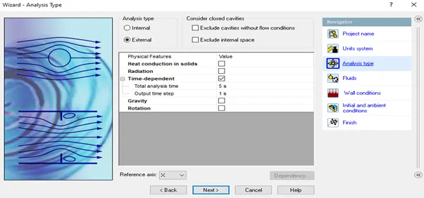
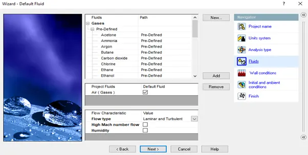
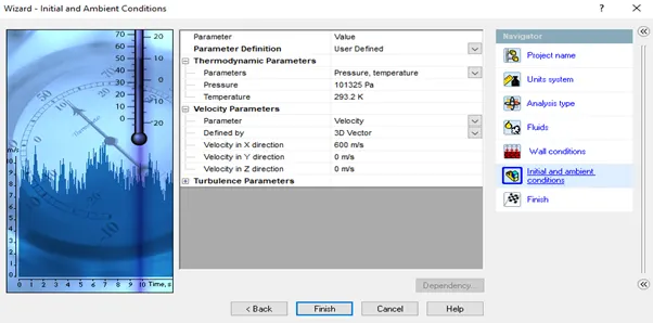
First open the solidworks part file, then go to Insert-Curve-Curve Trough XYZ Points to insert the airfoil 2D design and I had used "boeing 707 .08 span airfoil" data base. Using extrude comment bring up the 3D design of an airfoil and save that part file. After that follow the following condition to run the simulation process properly. Also the following setup is same for entire case study. there is velocity value is 600m/s, fluid is air and analysis type is external flow.

i)Initial Conditions:
Create the new flow simulation using the wizard comment. Here I had given project name, analysis type, fluid, wall conditions and initial conditions.
ii)computational domain:
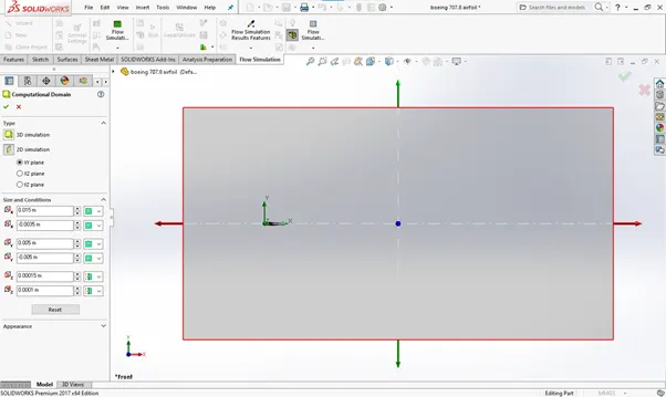
click the edit definition to change the type into 2D simulation and increase the boundary line size. The length from leading edge of the airfoil to front boundary line is 5 time of the chord line and the length from tailing edge to rear boundary line is 10 to 15 time of the chord line.
iii)mesh:
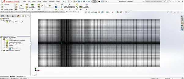
The process of subdividing the model into small pieces is called meshing. In solidworks the mesh is create automatically with recommended value. If you increase it then the result will come up with more precious. We have two type of meshing one is automatic and another one is manual.
iv)goals:
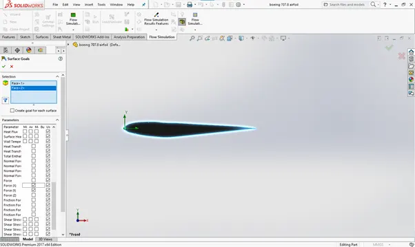
we can insert the five types of goals based on which type of result you want. I had inserted the surface goal using parameters force(x) also kwon as drag force and force(Y) also kwon as lift force to compare it for different angle of attacks.
RESULT:
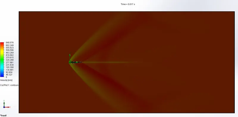
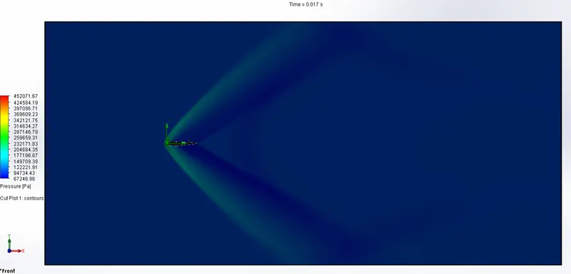
Case- 1: (angle of attack 0)
velocity
pressure
lift and drag summery

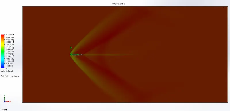
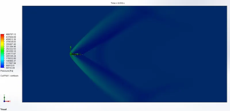
Case- 2: (angle of attack 2)
velocity
pressure
lift and drag summery

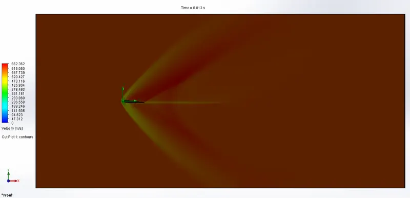
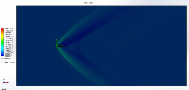
Case- 3: (angle of attack 4)
velocity
pressure
lift and drag summery

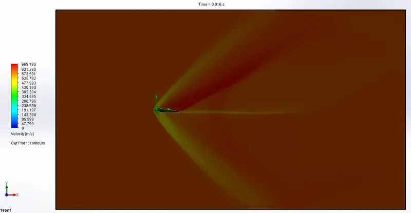
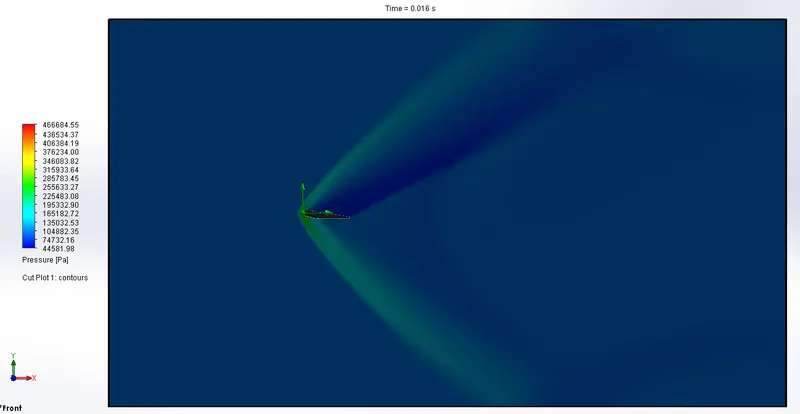
Case- 4: (angle of attack 6)
velocity
pressure
lift and drag summery

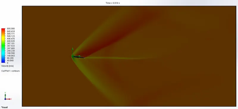
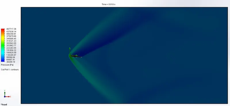
Case- 5: (angle of attack 8)
velocity
pressure
lift and drag summery

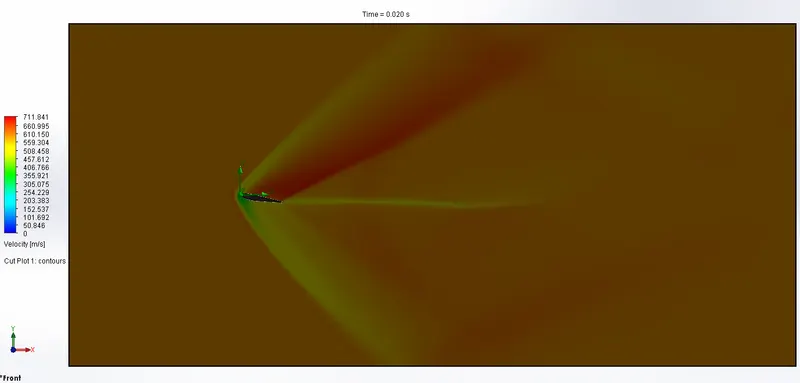
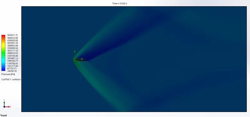
Case- 6: (angle of attack 10)
velocity
pressure
lift and drag summery

OBSERVATION:
|
angle of attack |
Velocity (min) |
Velocity (max) |
Pressure (min) |
Pressure (max) |
Force(x) drag force (min) |
Force(x) drag force (max) |
Force(y) lift force (min) |
Force(y) lift force (max) |
|
0 |
0 |
648.57 |
67246.96 |
452071.67 |
851.90 |
862.31 |
122.30 |
137.77 |
|
2 |
0 |
646.56 |
59743.08 |
466757.12 |
883.99 |
895.78 |
881.63 |
891.90 |
|
4 |
0 |
662.36 |
56576.97 |
468223.36 |
978.70 |
988.09 |
1617.57 |
1635.44 |
|
6 |
0 |
669.19 |
44581.98 |
466684.55 |
1115.92 |
1124.09 |
2362.18 |
2380.10 |
|
8 |
0 |
695.06 |
38208.18 |
467717.36 |
1293.61 |
1301.01 |
3072.43 |
3093.46 |
|
10 |
0 |
711.84 |
34250.35 |
503017.31 |
1540.80 |
1548.73 |
3853.88 |
3873.79 |
What I understood from the above table which I was calculated using different angle of attack is the velocity gradually increase and the difference in pressure is also apparent. But the purpose of this analysis is lift and drag force comparison so the answer to that is clearly available to us here. The drag force is increasing by multible for every angle of attack but the lift force is increasing at same value (avg: 750N).
So the force values are increase according to the angle of attack due to the stall point still not reach, the reason for this statement I have told in starting content.
CONCLUSION:
Flow simulation in solidworks also helps to analysis the flow over airfoil for different angle of attack. It is very important to all of us because we are all know about this airfoil design usage and its manufacturing difficulties.