Boeing-747 _ Final_Project
BOEING 747-8 AIRCRAFT MODEL DESIGNING AND RENDERING
SURESHKUMAR
INTRODUCTION
An aircraft is a vehicle or machine that is able to fly by gaining support from the air. It counters the force of gravity by using either static lift or by using the dynamic lift of an airfoil or in a few cases the downward thrust from jet engine. Here I had designed the boeing 747-8 using solidworks. On January 22, 1970, Pan American World Airways (Pan Am) flew the first commercial flight on a brand-new airliner – Boeing 747. So first we are all should know about the purpose of this project before start the modelling of boeing 747. After clear on it we are going to learn about the part modelling and surface modelling using the various commends in solidworks. we need to use the different appearances for various parts to easily identify each parts from a group after finishing the modelling. After finishing all the parts with proper constraints and dimensions we can assemble them using different mate comment. finally, we are going to learn about the rendering of the assembled model using photoview 360 with the help of adding cameras, decals, scene and lights. Not only that, but we can also render it with solidworks visualize software to bring up the realistic image by different plates and environment.
The components which we will learn in this boeing 747 are:
- Blueprint setup
- Boeing 747
- Wheel
- Nose gear base
- Nose gear suspension arm
- Main gear base
- Main gear suspension arm
- Engine
OBJECTIVE
- To address issues such as carbon footprint reduction, lower noise pollution and improved passenger comfort as well as contributing to national security.
- To build an aircraft that could fly more than the number of people that could be flown on any existing aircraft.
- To improve the speed of aircraft to reach designation with minimum time period.
- To reduce the maintainability though minimize the manual works and replace the mechanical components with sensors.
- To control the operating economy by improving the engine performance, monitoring fuel consumption, reduce the accidents, etc.
DESIGN PROCESS
The design process is an approach for breaking down a large project into manageable chunks. architects, engineers, scientists are use the design process to solve a variety of problems. Use this process to define the steps needed to tackle each projects, and remember to hold to all of your ideas and sketches throughout the process.

DESIGN APPROACH
There are two types of approach in design procedure. 1. Bottom up approach and 2. Top down approach. The difference between this two is the part file, because it’s not necessary to top down approach. Here in this project we have used Bottom-up approach and we get the clear idea by defining these terms.
- Top down approach: In the top-down model, an overview of the system is formulated without going into detail for any part of it. So you can start your work in the assembly and built parts to fit in the assembly. You can use the geometry of one part to help define the other parts or to create machined features that are added only after the parts are assembled.
- Bottom up approach: In this design, you can create parts, insert them into an assembly, and constraint them as required by your design. An advantage of bottom-up design is that, since components are designed independently, their relationships and regeneration behaviour are similar than in top-down design.
MODULES IN SOLIDWORKS
Solidworks extends design applications through full integration with best-in-class solution. And each module has different features and working procedures that will help on your design process. The following modules are explained below.
- Part modules
- Assembly modules
- Surface modules
- Sheet metal modules
- Drawing
- PhotoWorks
Part modelling:
This module produces parts easily and rapidly by creating features such as extrude, revolve, lofts, sweeps, patterns, etc. in solidworks, you can design a part by sketching its components shapes ad defining their size, shape and Inter-relationships.
Assembly modelling:
Assembly design gives a user the ability to design with user controlled associability. Solidworks builds these individual parts and sub-assemblies into an assembly in a hierarchical manner. This is based on relationships defined by the constraints.
Surface modelling:
For designing dies, castings or injections molds, surface modelling capability is important. Solidworks surface module can create complex models from free form shapes. You can create complex surfaces using lofts and sweeps with guide curve, drag-handles for easy control ad innovative surface feature.
Sheet metal design:
Sheet metal parts are generally used as enclosures for components or to provide support to other components. We can design a sheet metal part on its own without any references to the parts it will enclose. The main feature of sheet metal is its ability to be formed and shaped by a number of processes.
Drawing:
A 2D drawing view is a representation of a 3D cad part or assembly that is placed on drawing sheet. The drawing views represent the shape of the object when viewed from various standard directions such as front, side, top and so on.
PhotoWorks:
Photoview 360 is a solidworks add-in that produce photo-realistic rendering of solidworks models. The rendered image incorporates the appearances, lighting, scene and decals included with the model.
DESIGN METHODOLOGY:
First let’s see what basic sketch entities, features and constraints are in solidworks to create the parts.
SKETCH ENTITIES:
It helps user to create sketch required to feature creation. So we can use the specific number of sketch entities to create a 2D base sketch for parts development. Also the sketch tools are available to modify and edit the sketch for required shape.
Line: we can use the line entities to draw a straight line to connect the two points with required constraints along with proper dimensions.
Circle: we can use the circle entities to draw a circle based on center point that may be an origin point, vertex or anything.
Spline: we can use the spline entities to draw a special type of curves and critical shaped curves by connecting two or more points.
Rectangle: it’s closed sketch entities to draw a squares as well as rectangles from an origin, vertex, edges, or face center.
Arc: it is a portion of circle to connect the two points by drag the cursor based on center point or starting point.
Offset: add sketch entities by offsetting edges, faces, curves or sketch entities with a specific distance.
Trim: trim or extend the sketch entities used to deletes a sketch entities or a sketch entity to be coincident to another.
Sketch pattern: add sketch entities by linear or circular pattern based on direction and number of instance.
Mirror: we can mirror the selected entities about a center line or center plane.
Move/copy/rotate: we can move, copy, rotate, scale and stretch a sketch entity by defining the direction or base point.
FEATURES:
It helps user to create 3D sketch from 2D sketch by using required features in comment manager. also we can add or remove the materials from existing part model to satisfy the requirement. Before activate the feature comment we should verify that the 2D sketches are in fully defined sketch with proper dimensions and constraints.
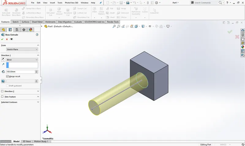
Extrude: we can add or remove the materials by specifying the directions and start point. At the same time user can use draft and thin feature to change the shape of model.
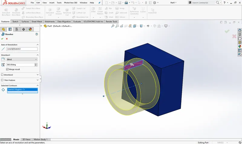
Revolve: it is same as extrude to add or remove the materials while give direction except specifying the axis of revolution to achieve the revolve feature. Thin feature is also here in revolve. And only we can revolve or revolve cut the closed sketch profiles. Open sketch profile cannot use to revolve feature.
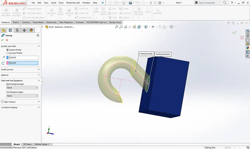
Swept: it is used to sweep a closed sketch profile along an open or closed guide path to create a solid part. We can develop the complex solid model based on guide path which gives the direction to base profile.
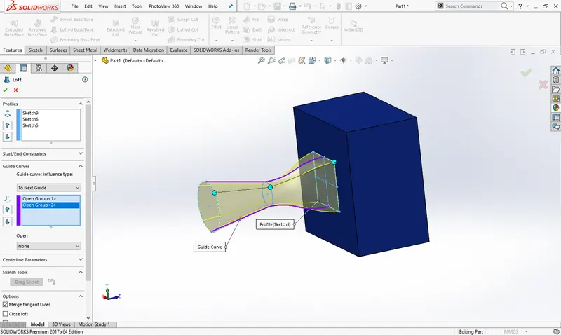
Loft: it is used to create a solid model between two or more closed profile whether using an open guide path or without guide path. Thin feature also is there to change the shape of model and we can use the start/end constraints to bring up the smooth surface finished solid model.
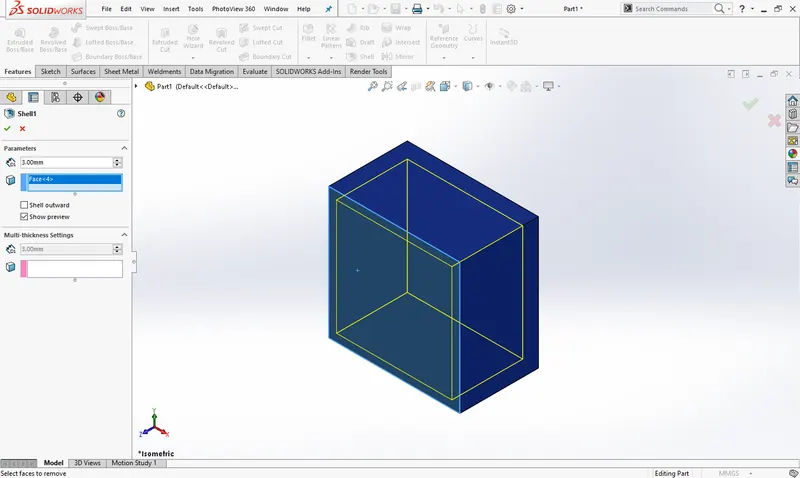
Shell: we can remove the material from a solid body to create a thin walled feature. In shell feature the selected faces will delete from body otherwise the shell feature lies inside the body if you are not select the any face.
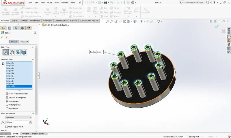
Fillet: it is very useful feature ever in any designing software because to remove the shape edges, increase the smoothness of edges it will help. There are many fillet option such as variable, round, face and constant fillet for our requirement.
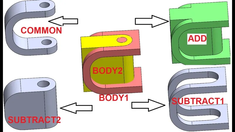
Combine: here we can add or subtract two different bodies which two bodies are in any contact with each other to bring the single part.
Mirror: mirror is widely using feature to reduce the number of step need to design a part. With the help of reference plane or face we can mirror the body or other features like fillet.
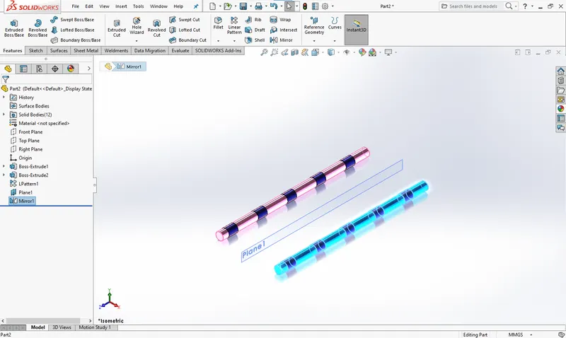
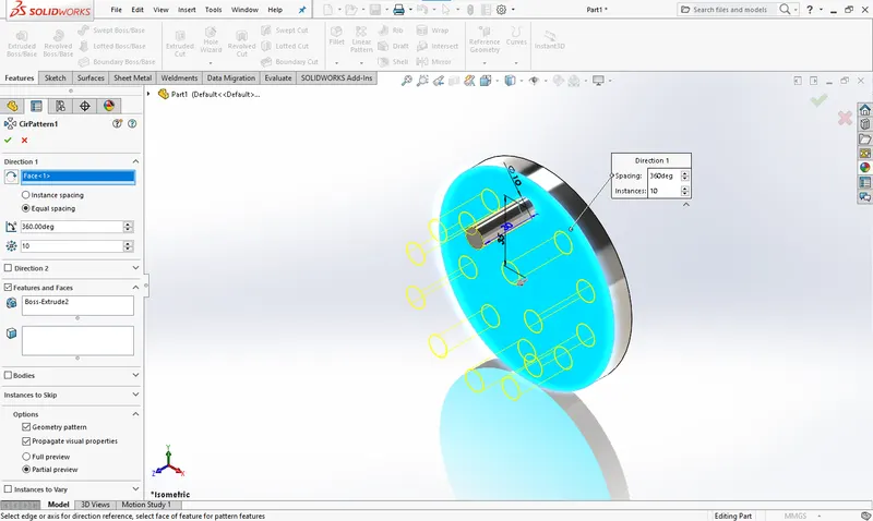
Pattern: after completely finished part or features we can pattern that by defining the direction and number of instance. It has also similar purpose as mirror to reduce the number of steps. And there are many types of patterns here to perform such as linear, circular, etc.
SURFACES:
Surface models are a type of 3D models with no thickness. This models are widely used in industries like automobiles, aerospace, medicals, and so on. In part modelling, you have created models with mass properties but surface models do not have thickness. The surfaces are generally used to create models of complex shapes.
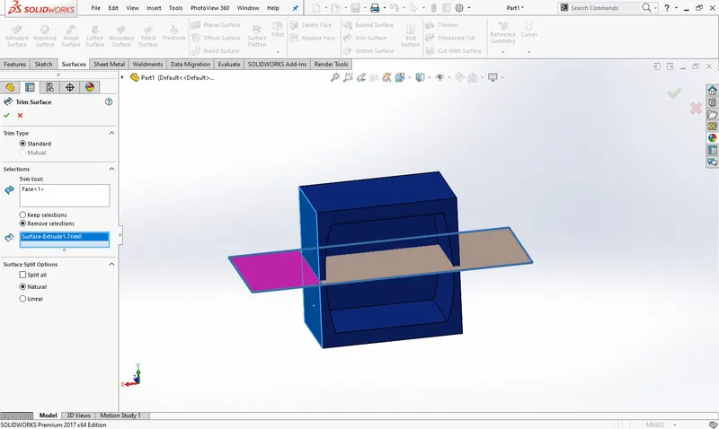
Trim surface: it removes a surface from target body where one surface intersects with another surface, a plane or a sketch. this allows even very difficult part design to be done.
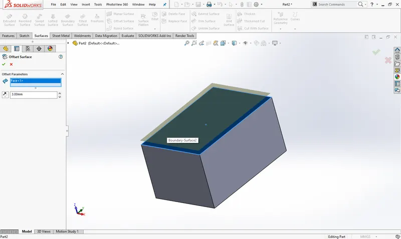
Offset surface: it creates surfaces from one or more continuous surfaces and faces with distance. It may be use in assembly modelling when you use it from base part to design other related parts.
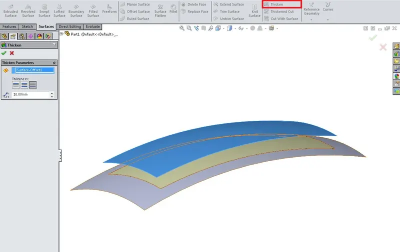
Thicken: to add material on existing part by defining the thickness value with the help of select any faces. Also there are thickness option for that like mid plane, upward and downward thicken.
Reference geometry:
We can use this feature often to draw the sketch like using this as permanent geometry we can start sketching easily. So lets me explain that clearly below.
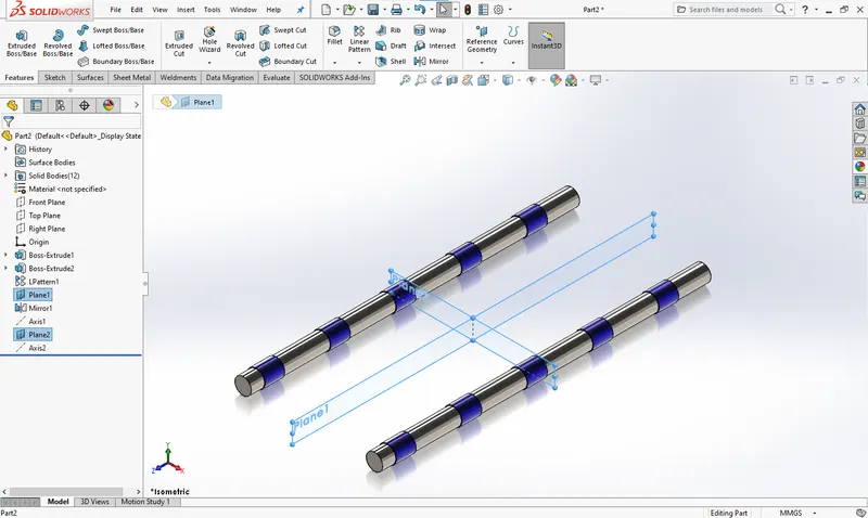
Plane: we can create the extra planes instead of primary planes. But this planes can be formed only from primary planes.
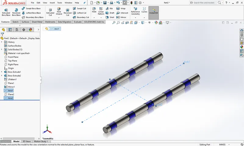
Axis: we can create the axis using planes, vertex, face, etc. this are all mostly use in assembly file to give mate comments.
CURVES:
This feature comments also similar with reference geometry. But it acts as a sketch to move on next feature. So let’s see this clearly below.
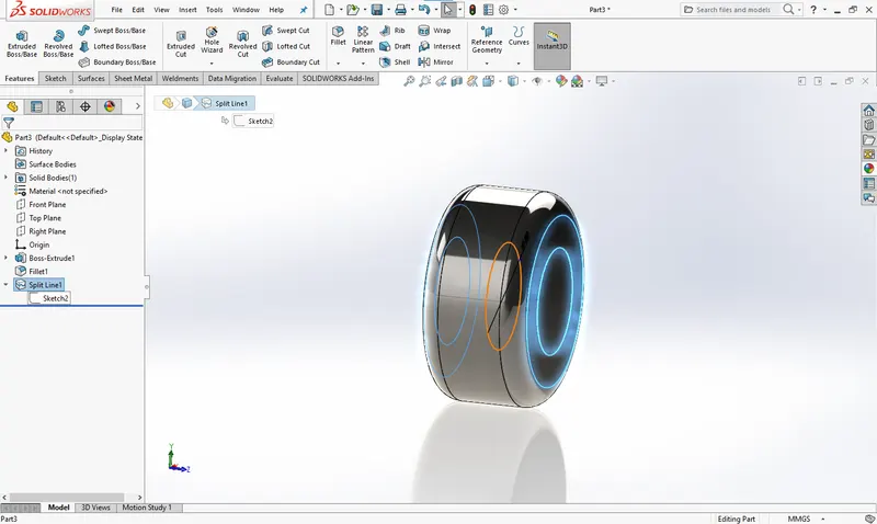
Split line: its only use for split the face or surface by using the sketch entity or blocks are already existing. It is very useful for give the various appearance to the models to improve the graphical look like beautiful.
Projected curve: sometime we need to draw the difficult 3D sketch but we don’t idea on it how to create 3D sketch. at the time we can use it to make it easier.
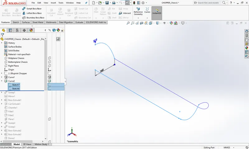
Mate: Mate feature creates geometric relationship between assembly parts. When we add mates, it defines the allowable direction of linear or rotational motion of component within its degree of freedom. Otherwise the assembly parts are fixed with base part and it will float along with base part. This feature includes as below:
- Coincident mate: it used to mate the two bodies coincident to make a contact with each other. After this mate the one part turns to get only the linear motion based on where we apply this mate like on face, corner or vertex.
- Concentric mate: two circular faces are mate concentric by its axis or circular edges. This mate allows the rotational motion about the axis.
- Distance mate: after selecting the mate references assign the distance to locate the parts.
- Gear ratio: it is mechanical mate used to run the gears properly and link with other gears to make the both gears have relative motions.
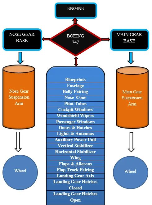
Now we have completed discussion of how the features work under solid works. Let us see the application of the features in the boeing 747 that we have built. We are going to discuss part by part as shown in the flowchart. So finally let’s start the boeing 747-part design procedure and every parts applications.
BOEING-747: The First Class and Business Class sections of the 747-8 enable airlines to offer passengers the most private and premium accommodations in the sky. So it's no surprise that on high-volume routes the 747-8 offers premium revenue potential. And with more than 400 seats available, this 747 creates a unique opportunity to maximize the bottom-line potential of any high-volume route. It's premium value, delivered, for operators and passengers. That's a better way to fly. Its initial design starts with blueprints using sketch entities and feature comments which are explained above.
Features used to create the boeing-747:
- Sketch entities
- Planes
- Extrude/cut-extrude
- Revolve
- Loft
- sweep
- Mirror
- Fillet
- Chamfer
- Surface offset
- Thicken
- Shell
- Combine
- Split line
- Linear pattern
Blueprints: it is basic thing ever in big projects to start off that design. Using primary and reference plane I had completed the blueprint setup.
Fuselage: it is a central portion of the body of an airplane, designed to accommodate the crew, passengers, and cargo. It varies greatly in design and size according to the function of the aircraft.
Belly Fairing: Also called a "ventral fairing", it is located on the underside of the fuselage between the main wings. It can also cover additional cargo storage or fuel tanks.
Nose Cone: A nose cone is the conically shaped forward most section of a rocket, guided missile or aircraft, designed to modulate oncoming airflow behaviours and minimize aerodynamic drag.
Pitot Tubes: it is used to measure flow speed. It's a slender tube that has two holes on it. The front hole is placed in the airstream to measure what's called the stagnation pressure. The side hole measures the static pressure. By measuring the difference between these pressures, you get the dynamic pressure, which can be used to calculate airspeed.
Cockpit Windows: On most passenger aircraft models, some cockpit windows can be opened. The main reason for having opening windows is for the pilots to be able to use them as exits in case of an emergency if the cockpit door is blocked.
Windshield Wipers: Windshield wipers are the most common rain protection feature. windshield wipers are operated by separate systems to ensure that clear vision is maintained. ach windshield wiper assembly consists of a wiper, wiper arm, and a wiper motor/converter.
Passenger Windows: A cabin window consists of three panes. 1)an outer pane flush with the outside fuselage, 2) an inner pane which has a little hole in it you may have spotted, and 3) a thinner, non-structural plastic pane called a scratch pane.
Doors & Hatches: Passengers board or exit from the plane through these doors. Specially engineered exit doors are designed so that they do not open during the flight and do not cause pressure loss. There are three types of doors on a plane: the passenger exits, the service doors, and the emergency exits.
Lights & Antennas: lights are used to signal that an aircraft is entering or approaching an active runway, or for visibility in dark, clear sky. An aircraft uses a range of radio frequencies to navigate to its destination and communicate with air traffic control. To do this successfully, the on-board radio equipment uses different types and sizes of antennas.
Auxiliary Power Unit: An Auxiliary Power Unit or APU allows an aircraft to operate autonomously without reliance on ground support equipment such as a ground power unit, an external air-conditioning unit or a high pressure air start cart.
Vertical Stabilizer: The vertical stabilizer keeps the nose of the plane from swinging from side to side, which is called yaw.
Horizontal Stabilizer: At the rear of the fuselage of most aircraft one finds a horizontal stabilizer and an elevator. The horizontal stabilizer prevents up-and-down, or pitching, motion of the aircraft nose.
Wing: Airplane wings are shaped to make air move faster over the top of the wing. When air moves faster, the pressure of the air decreases. So the pressure on the top of the wing is less than the pressure on the bottom of the wing. The difference in pressure creates a force on the wing that lifts the wing up into the air.
Flaps & Ailerons: Flaps help to either increase or decrease the camber, or surface area, of the airplane wing. Wing flaps are a significant part of the take-off and landing process.
Flap Track Fairing: A flap track fairing is a secondary structure whose function is to provide an aerodynamic cover and so reduce drag.
Landing Gear Axis: it is permanent axis for assembly file to make made feature easier with other parts.
Landing Gear Hatches Closed: after aircraft take-off we should close that hatches to reduce the aerodynamic drag force.
Landing Gear Hatches Open: for landing and take-off the aircraft we need to take out nose gear and main gear. At the time hatches are opening.
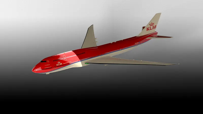
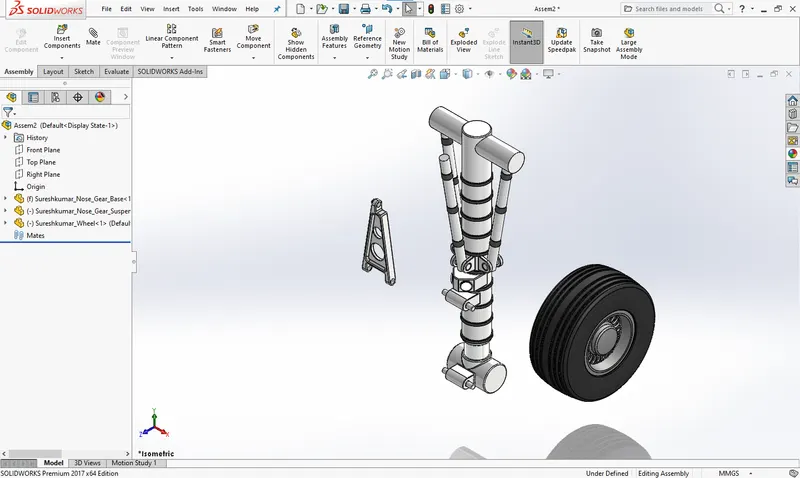
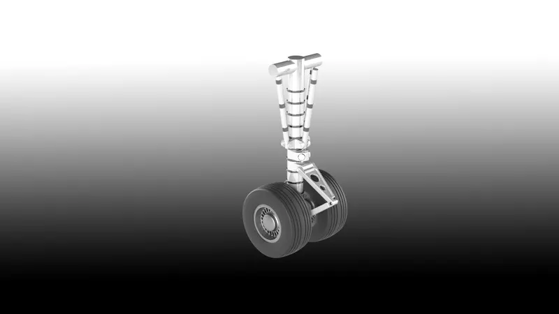
NOSE GEAR BASE: The landing gear in the nose of an aircraft is called the nose gear. Nose gear is the name given to the landing gear in the nose of an airplane. In any type of airplane that has a tricycle type of landing gear, the wheel, tire and components in the front of the plane are referred to as nose gear. Entire design mostly done with extrude, fillet and linear patterns.
Features used to create the nose gear base:
- Fillet
- Extrude
- Linear pattern
- Mirror
- Combine
- Circular pattern
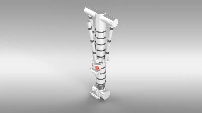
NOSE GEAR SUSPENSION ARM: suspension arm used to reduce the vibration on aircraft and gives smooth landing. It’s a simple design there is no difficulties. Its connect the wheel axle and fuselage through one or two suspension arms.
Features used to create the nose gear suspension arm:
- Extrude
- Fillet
- Cut-extrude
- Mirror
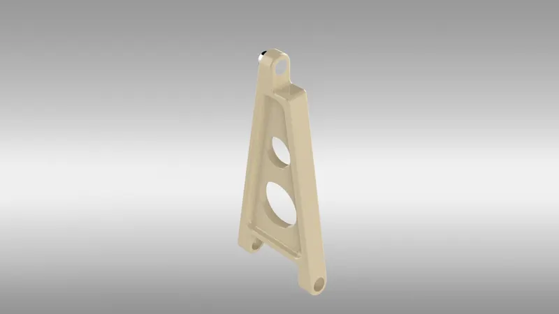
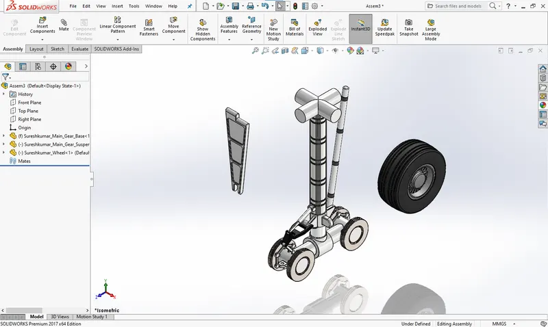
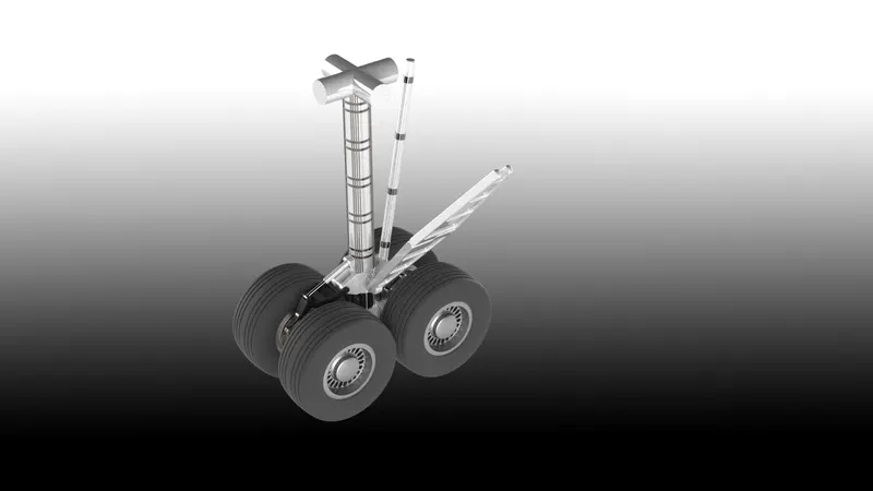
MAIN GEAR BASE: Main landing gear, positioned nearest to the CG of the aircraft, touches the ground first while landing and leaves the ground last during take-off. It is also similar design as nose gear base except wheel base because total mass of the aircraft is carried out by main gear wheels.
Features used to create the main gear base:
- Extrude
- Cut-extrude
- Filet
- Mirror
- Linear pattern
- Plane
- Sweep
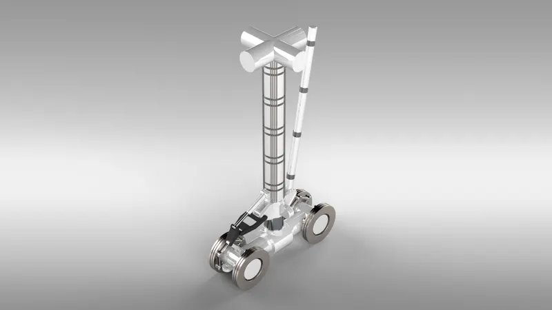
MAIN GEAR SUSPENSION ARM: It has also similar purpose as nose gear suspension arm except size because it should maintain the maximum amount of vibration during landing. But same designing approach.
Features used to create the main gear suspension arm:
- Extrude
- Cut-extrude
- Fillet
- Reference axis
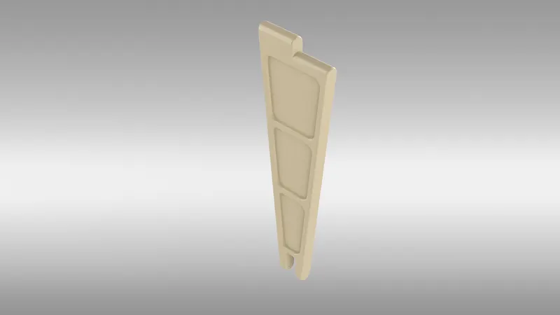
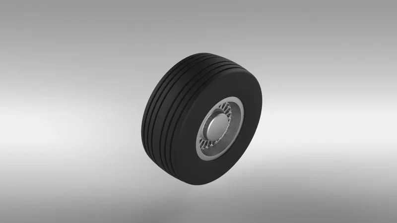
WHEEL: Aircraft wheels are an important component of a landing gear system. With tires mounted upon them, they support the entire weight of the aircraft during taxi, take-off, and landing. The typical aircraft wheel is lightweight, strong, and made from aluminium alloy. Some magnesium alloy wheels also exist. Here the wheel design did complete with tire, rim and bolt heads.
Features used to create the wheel:
- Revolve
- Revolve-cut
- Fillet
- Mirror
- Circular pattern
- Extrude
- Cut-extrude
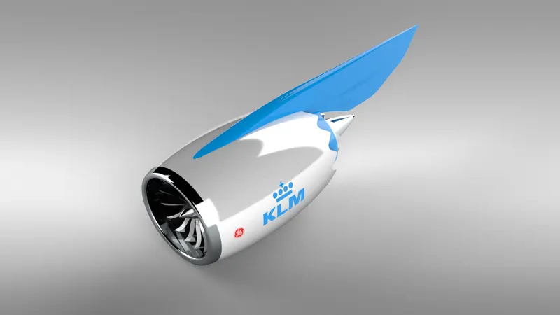
ENGINE: An airplane engine provides a constant supply of air for the pressure vessel. An airplane turbine engine operates with the same 4 basic steps as a lawnmower or automobile engine. An airplane turbine engine has sections that perform each of the 4 basic steps of intake, compression, combustion, and exhaust. Using the blueprint engine design started in solidworks. There are five bodies such as blades, cowl, exhaust nozzle, engine and pylon had designed which satisfied that blueprint.
Features used to create the engine:
- Blueprint
- Revolve
- Revolve-cut
- Fillet
- Extrude
- Split line
- Split
- Circular pattern
- Thicken
ASSEMBLY:
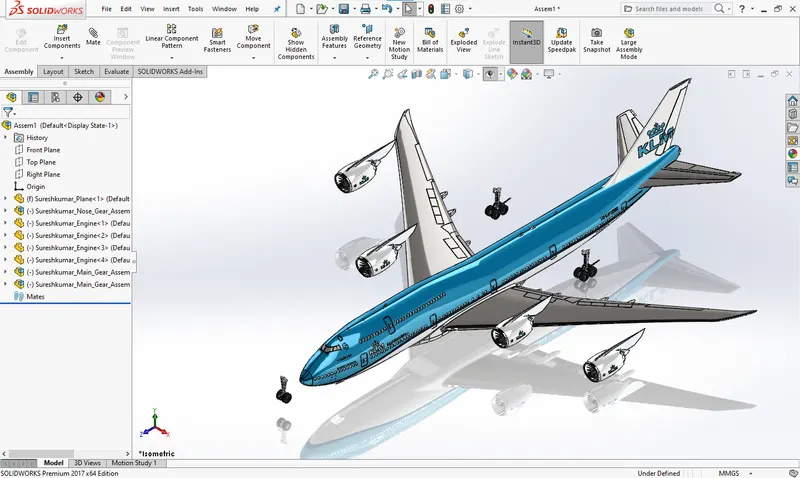
All the parts were modelled and imported into solidworks assembly file to assemble them. In assembly modelling the mate feature is most commonly used to locate and relate the parts with another one. Fuselage is main component which is inserted first and It will be fixed automatically. The other components were inserted one by one into the assembly file. By using the planes, faces, edges or axis for reference and giving the mate feature. once the part gets fixed then it floats with the main part which part were inserted first. Some parts were modified during assembly to make it perfect according to requirement. Here I created there are three assembly files to complete the Boeing 747 model.
1.Nose gear assembly:
 2.Main gear assembly:
 3.Final assembly:
RENDERING:
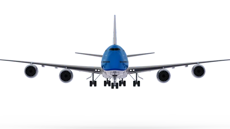
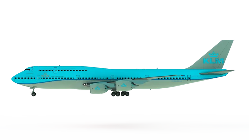
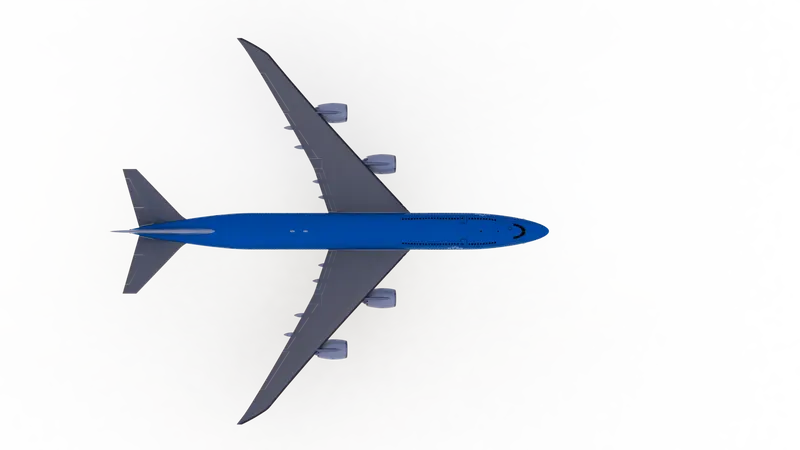
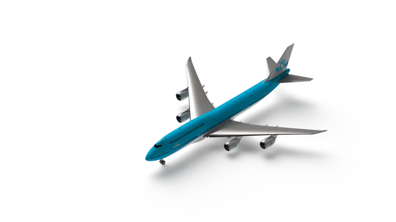
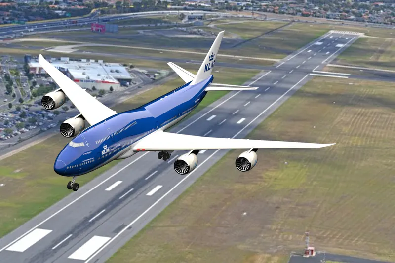
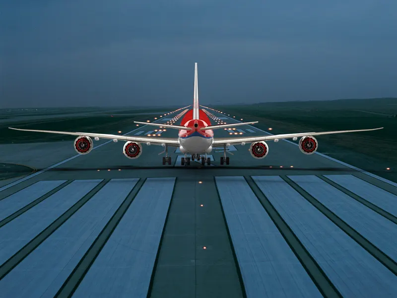
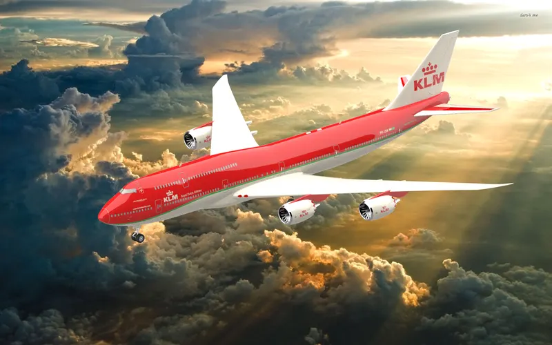
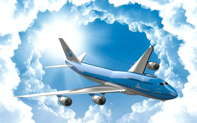
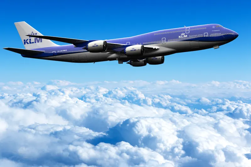
The term “rendering” comes from the graphic world where a rendering is an artistic drawing of what a new structure would look like. In computer aided design, a rendering is a particular view of a realistic image. By doing rendering of Boeing 747 we get the idea that how it will look into the environment. This rendering is done in the “solidworks visualize” software as well as “photoview 360”. By using photoview 360 we can render the model through adding various cameras, lights, decals to that model. Also to get the perfect realistic view we need to set various angles, direction, and set appropriate distance. In “solidworks visualize” rendering we can change the appearance of parts, background images, environments, brightness, rotation and various setting of Boeing 747. Including the resolution and setting number of passes we get more detail visuals of Boeing 747.
- Rendering on photoview 360:
- Rendering on solidworks visualize:
Conclusion: Boeing 747 design has conformed to the project aims and objectives. It has been successfully designed and assembled using solidworks to optimise the Aircraft system. The appropriate components for the Boeing 747 and their purpose were researched from the various references. In addition to component research a broader knowledge was gained from aircraft system and this information proved essential for gaining a better understanding of aircraft components. Finally, a design process was implemented in a chronological order starting with empathise, define, ideate, prototype and test.