Project - Speed Control of a Direct Current (DC) motor
%DC Motor parameters for PID control
J=0.01; %Moment of Inertia of rotor in kg/m^2
B=0.1; %Motor Viscous friction in Nms
Km=0.01; %Back EMF constant in V/rad/s
Kt=0.01; %Motor torque constant in Nm/A
Ra=1; %Resistance of Armature ckt in ohm
La=0.5; %Inductance of Armature ckt in Henry
%Kp, Ki and Kd used in PID design of Speed control of DC motor
Kp=3.8602; %Proportional gain
Kd=6.2832; %Derivative gain
Ki=0; %Intergral Gain
%In the above code and values the value of Ki is taken as 0 because when the value was assigned to the Ki other than zero the parameters were approaching infinity, which is not a favorable condition for speed control of DC motor.
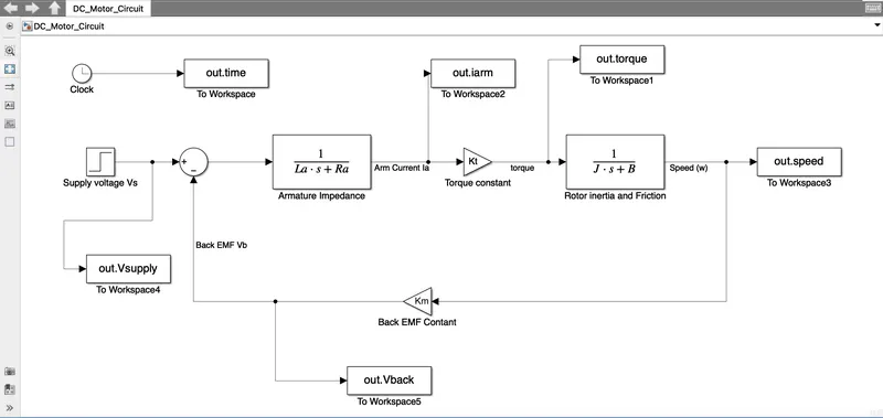
Below is the Model of the DC motor according to the circuit shown above.
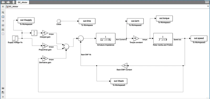
Below is the Model for the PID controller for the speed control of the DC motor. In this model the PID controllers are added with the values shown above.
The input and control designs were kept under certain conditions such as
Settling time <2sec
Overshoot<5%
Steady-state error<1%
These parameters can be considered that it will keep the system in a stable state as fast as possible.
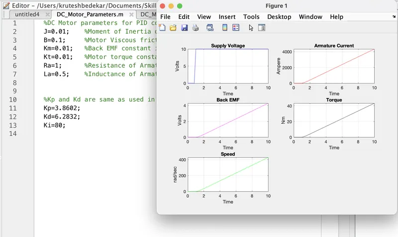
In the case shown below the value of Ki is kept as 80 which results in a ramp-like output that approaches infinity and hence the system doesn't achieve stability.
Then keeping Ki as 0 and the rest of the gains the same as above we get the following plots which are stable in the prescribed time of 2 sec.
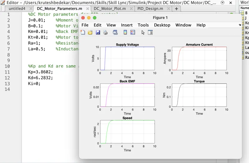
Hence here is the speed control of the DC Motor.