Week-11 Challenge: Braking
1)
Braking:
Braking is the process of slowing down or stopping a moving vehicle when necessary. Brakes can be applied using a variety of mechanical or electrical means. The method that uses friction is the most popular. It consumes energy. Consumed kinetic Energy can be derived as following equation
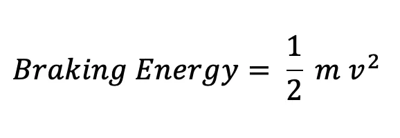
where braking energy is in Joules
M is the total mass of the vehicle and load mass in kg
and v is the differential velocity of the vehicle (Final - initial velocity) in m/s
Here is shown the drive cycle as an example for this question.
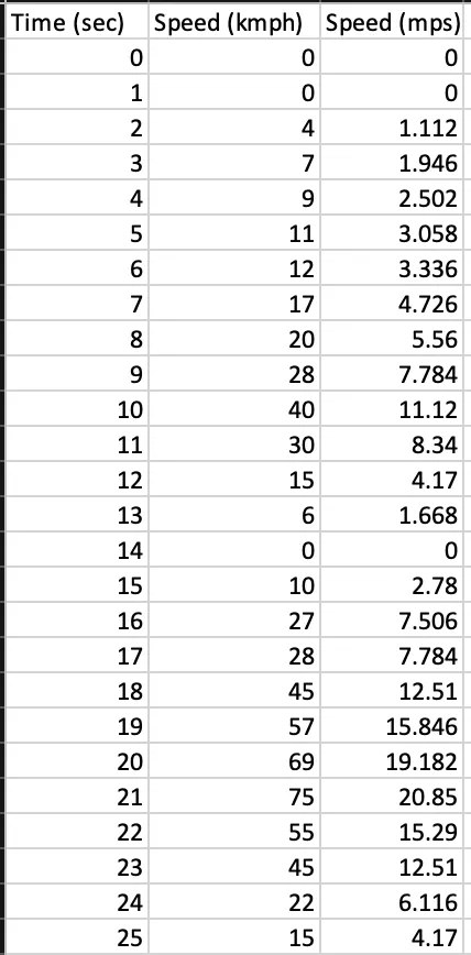 .
. 
The graph plotted using Excel feature 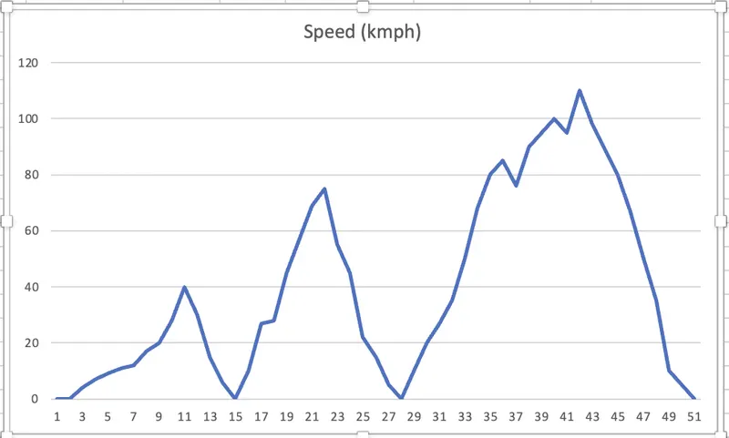
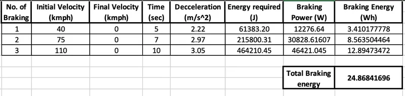
The excel sheet calculation and the total braking energy required for this drive cycle.
__________________________________________________________________________________
2)
Braking:
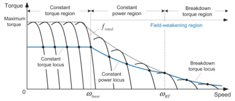
As we can see in the plot below that at stalling torque i.e. at the time of starting the speed is zero or less, which enables us to apply brakes at that particular moment, but when the speed increases the momentum of the vehicle is such that braking the speed and motion of the vehicle can be dangerous or it may require huge energy to apply brakes.
Only at high speeds does this problem arise because the motor will be operating in the constant power range. The motor's torque decreases in the constant power range, making it impossible for the motor to produce braking torque equivalent to that produced at low speed in the constant torque band.
Types of braking that can help in applying braking of the electric motor are:
(i) Mechanical Braking:
In the case of braking electrical motor, a technique or external braking can be used, with the help of some mechanical or mechanized braking system other than electrical signals or system.
The frictional force is here employed to stop the wheels that are connected to the motor, this would reduce the momentum of the vehicle.
There are types of mechanical braking systems that can be used according to the requirements:
(ii) Electrical Braking:
Electric brakes are tools that slow down or halt the rotation of a rotating component using an electrical current or magnetic actuation force. They are utilized in applications requiring quick response times and accurate tension control in both industrial and automotive braking systems.
Two conductor wires on the magnet in the backing plate tap directly into the wiring. The brake magnet becomes magnetized when the electricity is on. The magnet is drawn to the surface of the drum. It rotates when it comes into touch with this area due to friction, which moves the actuating arm and forces the shoes up against the drum. These shoes are made of a unique brake pad material that withstands the heat produced by friction.
The hub and, as a result, the wheel that is touching the ground is prevented when the shoes press against the inside of the drum.
Regenerative braking plays an important role in electrical braking as well as when it comes to HEV in which the battery can be recharged using the motor as a generator for the battery using a converter.
How electric and mechanical brakes are coordinated:
In this mechanism the mechanical braking and electrical braking (mainly regenerative braking) is used in a pattern that helps in braking an Electrical vehicle.
When the brake pedal is depressed, hydraulic fluid travels to the brake pistons and generates braking pressure on the wheels. Regenerative Braking then uses the same kinetic energy by employing a bi-directional motor that acts as a generator while braking to produce extra power.
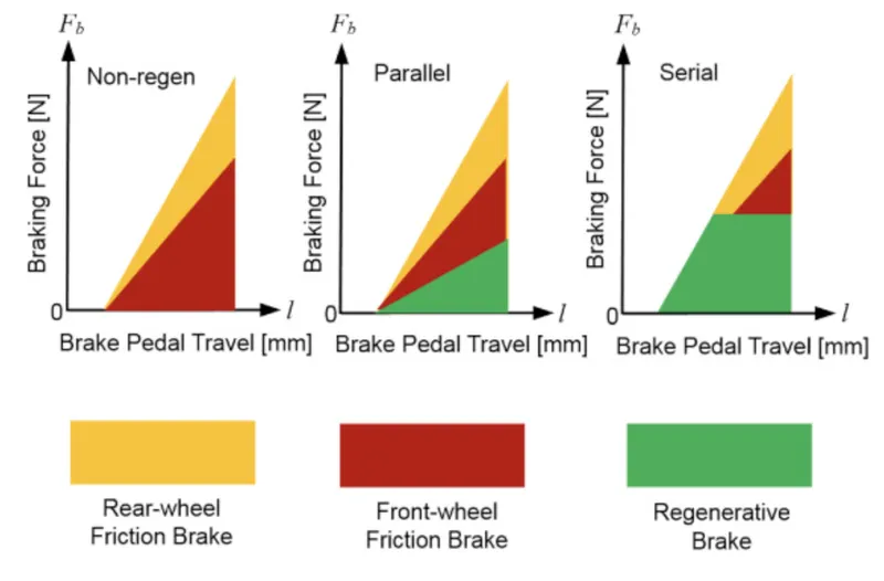
- Series: In this mechanical and regenerative braking is applied in an alternate pattern or one after the other.
- Parallel: In this mechanical and regenerative braking both are applied simultaneously.
__________________________________________________________________________________
3)
__________________________________________________________________________________