Week-6 Challenge: EV Drivetrain
1)
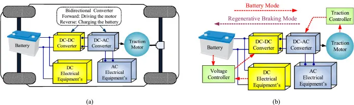
The components used in EV and HEV can be understood by the layout shown below,
In the figure shown above, there are different components including a Fuel tank, Engine (in the case of Hybrid), Battery pack, Power Electronic converter, Traction motor, and Transmission.
The Power electronic converter can be further elaborated in the type of conversion of the supply type.
- AC to DC ----> Rectifier: It is used when the EV or HEV is to be charged from a general AC supply at our homes or charging stations. Just like UPS it will charge the battery pack by converting the AC supply to DC.
- DC to AC ----> Inverter: The battery after being charged has to supply power to the traction motor to move the EV and hence it requires AC supply for better results. Hence here inverter is used to feed the motor with an AC supply when we have DC as the stored supply option in the battery.
- DC to DC ----> Chopper and Converters: This converter is used to reduce the voltage level of the battery voltage to run the auxiliary system of the EV, such as headlights, music system, lights, etc.
Step-down chopper /Buck converter: This is mostly used in the above explanation, that reduces the voltage level of the battery pack to feed to the smaller, low voltage appliances.
Step-up chopper/Boost Converter: This is used in the case when the voltage level has to be raised for a certain application.
Unidirectional converter: This converter has the capability to converter i.e. step-up or step-down in one flow direction of the power supply, i.e. one input and only one output side.
Bidirectional converter: This converter is capable to change the voltage level from both sides of the circuit..
__________________________________________________________________________________
2)
Given data ,
Battery pack in EV (Armature voltage)= 72 V
Armature current (Ia)= 400 A
Armature Resistance Ra = 0.5 Ω
Motor constant = 0.7 Vs
Chopper Switching frequency = 400 Hz
Duty cycle = 70% = 0.7
Actual Voltage (V) = 72*0.7 = 50.4 V
Now by using the Torque-speed equation for motor
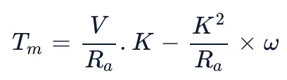 --------- (1)
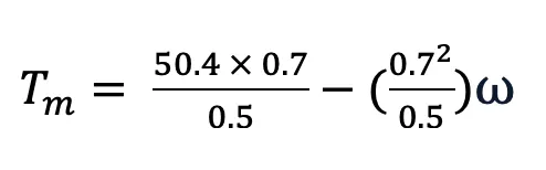
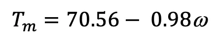 -----------(2)
We have a given equation
 ----------------(3)
At steady state
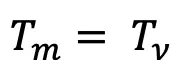 ----------------(4)
Equating the equations

Solving the quadratic equation, we get
ω = 38.92 or ω = -231.07
So accepting the positive value
ω = 38.92 rad/s
__________________________________________________________________________________
3) The Simulink Model for the equation is shown below
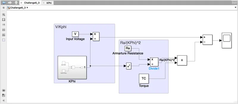
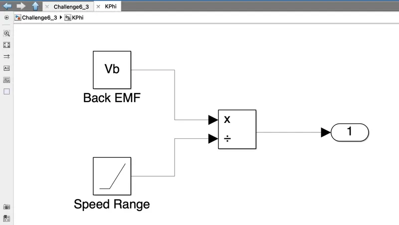
Explanation of Model:
- The Value of KΦ is found by dividing Back EMF by Speed range.
- Then according to the equation Supply voltage is divided by KΦ block output.
- Similarly the value of Ra as an input is divided by (KΦ)^2 and mutilplying by T.
- Then calculating the equation by the substract block.
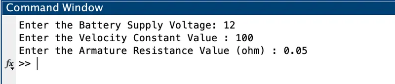
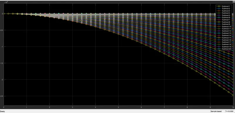
The Parameters and the simulation were done on the DC model created in the week 5 assignment