Project - Position control of mass spring damper system
Aim:-Obtain the transfer function of a mass spring damper system and use it in the model. Add a PID controller to adjust the force on mass so that its position follows a reference signal.
Take m = 3.6kg ;k = 400N/m; c = 100Ns/m
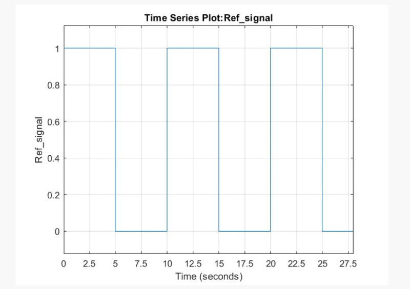
The reference signal is shown in the following figure.
Solution :-
Blocks used :
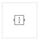
Integrator: Integrate signal
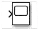
Scope: Display signals generated during simulation.
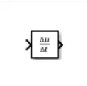
Derivative - Output time derivative of input
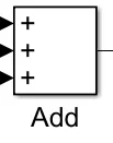
Sum:The Sum block performs addition or subtraction on its inputs. The Add, Subtract, Sum of Elements, and Sum blocks are identical blocks. This block can add or subtract scalar, vector, or matrix inputs. It can also collapse the elements of a signal and perform a summation.

Add:Add or subtract the inputs
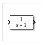
Transfer fcn:Model linear system by transfer function.The Transfer Fcn block models a linear system by a transfer function of the Laplace-domain variable s. The block can model single-input single-output (SISO) and single-input multiple-output (SIMO) systems.
In 1: Provide an input for a subsystem or model

out1:Provide an output for a subsystem or model
Subsytem : A subsystem block template containing an inport and outport block
Pulse generator :Generate square wave pulses at regular intervals
Mux - Combine input signals of same data type and complexity into virtual vector
Procedure :
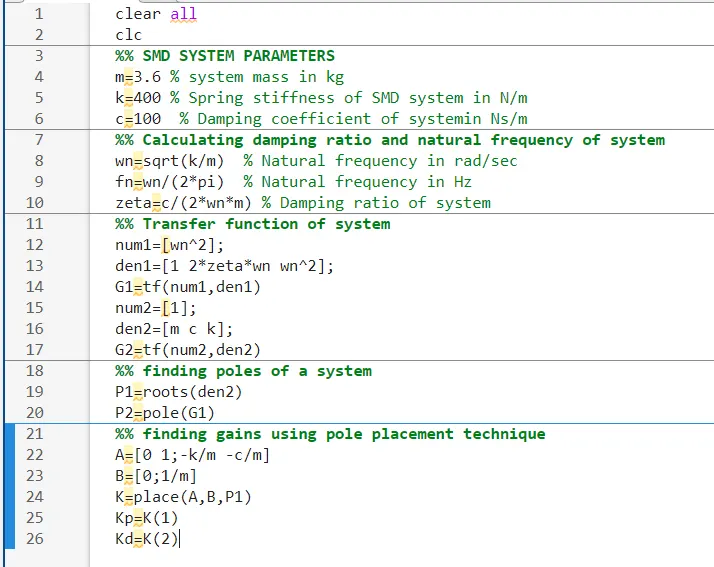
To find the gains for pid controller we are using pole placement method.we can write script for to get gains like below.
Then go Simulink and create the model
. first go to library browser and drag the pulse generator.by using this we create reference signal.
we provide values to pulse generator block like below
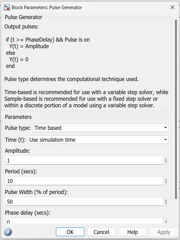
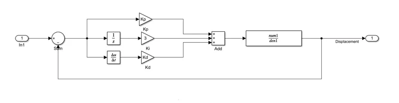
For this Mass spring damper system we can create pid controller manually or we have PId controller block.
First we create Mass Mass spring damper system with manual PId controller.
Now we create Mass Mass spring damper system Automatic PId controller.
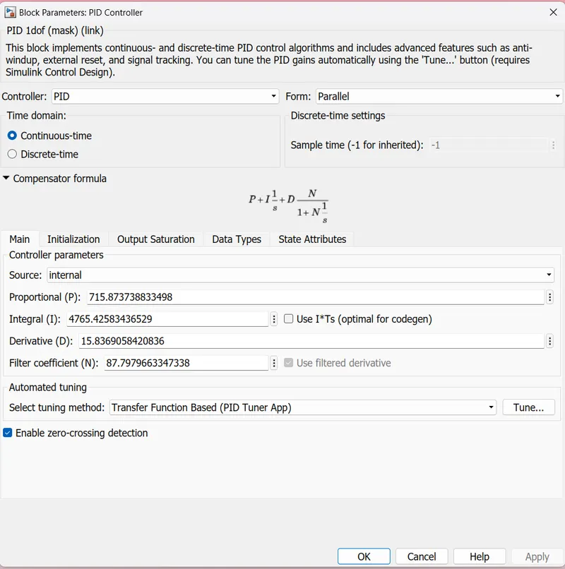
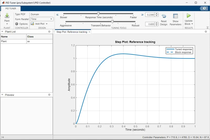
for Automatic PID controller we need to check the tunining.as per tune response we can change tuniing manually to get desired response .
After that click on the Update Block.
Select both models to create subsystem and bottom we are seen 3 dots ,click on that in which we have subsytem option.
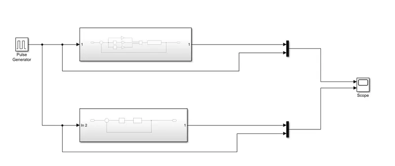
Then run scrpit in matlab to get inputs for our model.
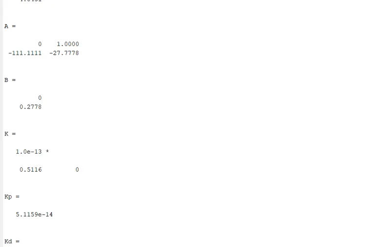
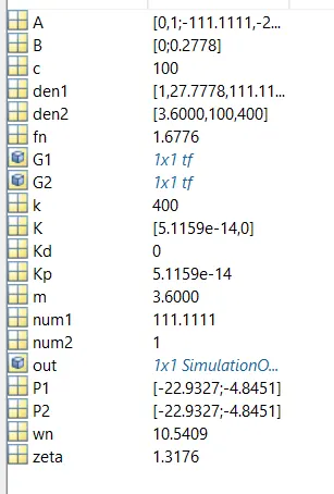
Then move to simulink and click on Run.we get results like below.
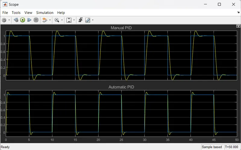
In which first plot belong to Spring mass damper system with Manual PID controller.In which for gain Ki we are provide value manually by trail and error method.
In scope block Second plot belong to Spring mass damper system with Automatic PID controller.In which all gain values it will take automatically as per our model.
Compared to manual Pid ,Automatic pid controller is more efficient.