Project - Analysis of a practical automotive wiring circuit
Title: Analysis of a practical automotive wiring circuit
Objective: Analysis of electrical circuit and provide solutions for the related question.
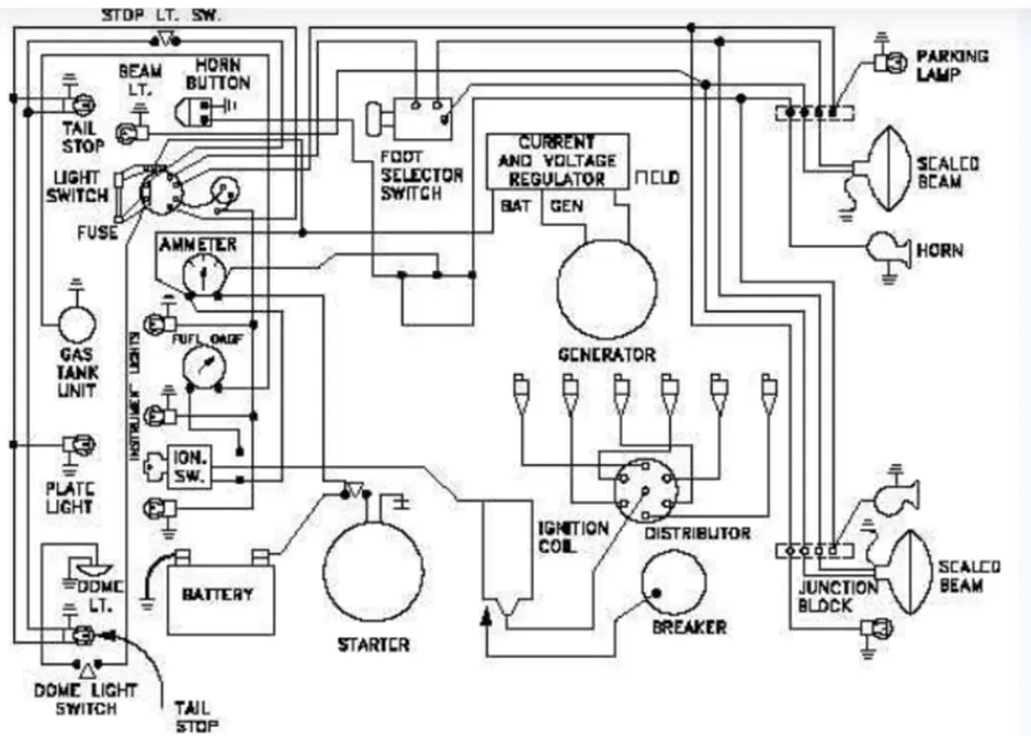
•Identify each of the major elements in the above automotive wiring diagram.
Ans: The major elements of the above image are listed below:-
Battery: Batteries provide the energy to “push” the charges through the resistors in the circuit by converting chemical potential energy into the electrical potential energy of the charges.
Breaker: A circuit breaker is an electrical safety device designed to protect an electrical circuit from damage caused by overcurrent. Its basic function is to interrupt current flow to protect equipment and to prevent the risk of fire.
Distributor: Power distributors and dispatchers control the flow of electricity traveling from generating stations to substations and to users.
Generator: Electric generator works on the principle of electromagnetic induction. The principle of electromagnetic induction states that the change in the magnetic field around a conductor generates electric current in the circuit. When a coil rotates in a magnetic field a current is induced in the coil.
Current Regulator: A circuit designed to keep the current flowing through a circuit at a constant rate is a current regulator.
Voltage Regulator: A voltage regulator is a circuit that creates and maintains a fixed output voltage, irrespective of changes to the input voltage or load conditions.
Foot Switch Selector: This switch includes two contact points and the wires of this switch are simply connected to the circuit in a device. When Normally Open (NO) contacts within the switch are not getting connected, then the circuit in the device is not connected, so the device will be turned OFF.
Fuse: The primary use of an electric fuse is to protect electrical equipment from excessive current and to prevent short circuits or mismatched loads. Electrical fuses play the role of miniature circuit breakers.
Ammeter: An ammeter is connected in series with the circuit to measure the entire flow of electrons (current). The measured current and the internal resistance of the ammeter are the sources of power loss in the device.
Ignition Coil: It is used in the ignition system of a spark-ignition engine to transform the battery voltage to the much higher voltages required to operate the spark plug(s).
Junction Block: It is where electrical wires come together and connect to form a circuit. Junction boxes help to protect the circuit from electrical hazards by providing a safe place for wires to connect.
• Explain the purpose and working of any three elements briefly.
Ans: 1) Battery: Batteries provide the energy to “push” the charges through the resistors in the circuit by converting chemical potential energy into the electrical potential energy of the charges.
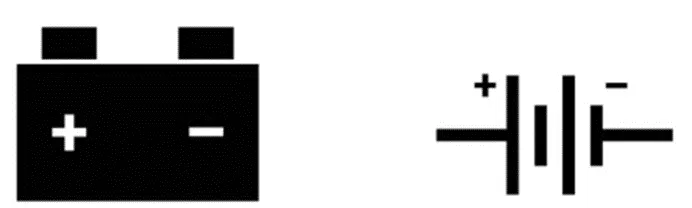
By moving charge to high energy, the battery (or cell) is establishing a difference in electric potential across the two ends of the external circuit. With this difference in electric potential established, charge will spontaneously flow through the external circuit.
The battery's role in a circuit is all about doing work and providing energy. It supplies this energy by means of an electrochemical reaction which establishes an electric potential difference between the two terminals of the battery. The chemical reaction involves reactants and products.
2) Generator: Electric generator works on the principle of electromagnetic induction. The principle of electromagnetic induction states that the change in the magnetic field around a conductor generates electric current in the circuit. When a coil rotates in a magnetic field a current is induced in the coil.
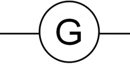
Principle of electric generator:
Electric generator works on the principle of electromagnetic induction.
The principle of electromagnetic induction states that the change in the magnetic field around a conductor generates electric current in the circuit.
When a coil rotates in a magnetic field a current is induced in the coil. The direction of the induced current is given by Fleming's right-hand rule.
3) Distributor: The primary purpose of an electricity distribution system is to meet the customer’s demands for energy after receiving the bulk electrical energy from transmission or sub transmission substation. There are basically two major types of distribution substations: primary substation and customer substation. The primary substation serves as a load centre and the customer substation interfaces to the low voltage (LV) network.
• If the total load is 10A from battery, what should be the fuse rating?
Ans: As it is recommended that “the voltage rating of the fuse must always be higher than the voltage rating of the circuit that it is protecting.”
When specifying a fuse for an after-market application, the key consideration is that the fuse should be the weakest point (i.e. lowest rated component) so that it always blows before any damage occurs to other parts of the electrical circuit. However, you also do not want the fuse to keep blowing under normal operation (known as a nuisance blow), so the two elements to consider are:
• The current rating of the smallest cable in the circuit
• The current draw on the circuit under normal expected operating conditions
Henceforth, if the normal expected current draw is 10A and the cable size is 25A, then a fuse rated at 15A would be appropriate.
If 500W is the load, what is the voltage and capacity of battery you recommend?
Ans: Given: Load=500W and Battery voltage= 12V
As, The capacity of the Battery is in (Ah) = I*t
Power is in (Wh) = V*I*t
=> (Power or Load)/V = I*t
=>So, the Capacity of the Battery = 500/12 = 41.6Ah
• Identify any two elements which are connected parallel to each other. Why they are connected in parallel?
Ans: Tail Stop Light and Beam Light are connected in Parallel to each other.
Reasons: They are connected in parallel to each other to get their rated voltage so that they function efficiently. They have their independent switch to control them. If one gets faulty, it doesn't affect the other.
• Identify any two elements which are connected in series. Why they are connected in series?
Ans: Ammeter and Current regulator is connected in series.
Reason: Ammeter is used to measure the current flowing through a component/circuit. Since, current remains same in series connection and also the resistance of an ammeter is very small due to which it doesn't affect the current to be measured. So, an ammeter is connected in series to measure current with respect to the current regulator.