Project
Aim: To Carry out a system-level simulation of a BAJA all-terrain vehicle and Prepare a technical report explaining the model properties.
Main components used in the model:
Signal builder block:
Create and generate interchangeable groups of signals whose waveforms are piecewise linear, The Signal Builder block allows you to create interchangeable groups of piecewise linear signal sources and use them in a model. You can quickly switch the signal groups into and out of a model to facilitate testing. In the Signal Builder window, create signals and define the output waveforms.
Generic engine:
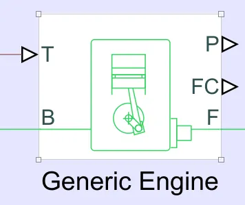
The generic engine represents a system-level model of spark-ignition and diesel engines suitable for use at the initial stages of modeling when only the basic parameters are available. Optional idle speed and red line controllers are included.
The throttle input signal T lies between '0' and '1' and specifies the torque demanded from the engine as a fraction of the maximum possible torque. If the engine speed falls below the Stall speed, the engine torque is blended to zero. If the engine speed exceeds the maximum speed, the simulation stops and issues an error message.
Connections F and B are mechanical rotational conserving ports associated with the engine crankshaft and engine block.
Connections P and FC are physical signal output ports through which engine power and fuel consumption rate are reported.
Engine sensor:
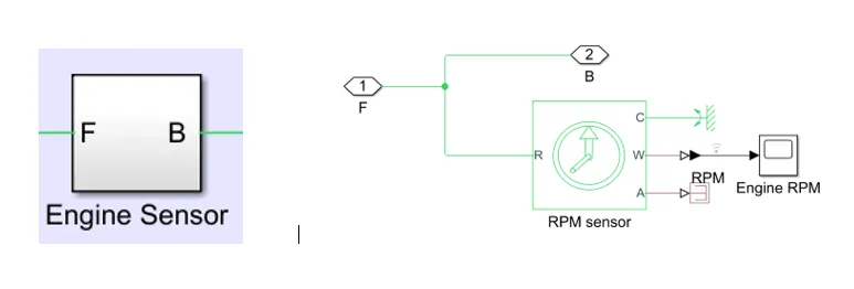
The engine sensor is used to record the angular velocity of the engine shaft.
CVT:
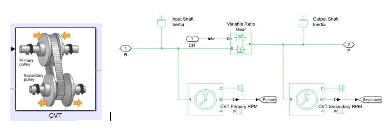
A CVT, or continuously variable transmission, seamlessly changes through an unending range of effective gear ratios while you drive, whereas other kinds of mechanical transmissions offer a fixed number of gear ratios and have hard shifts between each as explained by Certified Transmission Repair. CVT transmission systems are also known as single-speed, shiftless, and stepless transmissions.
The shiftless nature of a CVT offers unparalleled flexibility that maintains constant angular velocity regardless of output speed. Additionally, a continuously variable transmission makes accelerating smooth and offers enhanced fuel economy.
CVT systems work through a pulley system. In short, this system consists of cones at each pulley connected via a chain belt. The cones can move to increase or decrease the belt diameter to change gear ratios, allow for quick shifting into the needed ratio for increased power, and boost fuel economy.
Inertia:
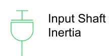
The block represents an ideal mechanical rotational inertia.
The block has one or two mechanical rotational conserving ports. The difference is purely graphical, as the ports are rigidly linked. The block's positive direction is from its port to the reference point. This means that the inertia torque is positive if the inertia is accelerated in the positive direction.
Variable ratio transmission:
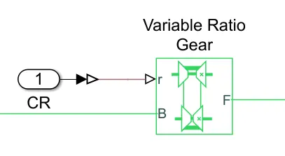
This block represents a variable ratio gearbox such as implemented by mechanical belt CVT, electric, or hydraulic transmissions.
Connections B (base) and F (follower) are mechanical rotational conserving ports. Specify the relation between base and follower rotation directions with the Output shaft rotates parameter.
Ideal Rotational motion sensor:
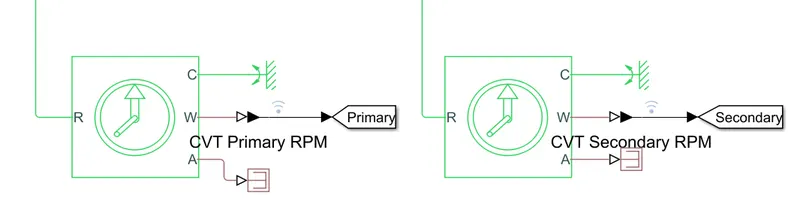
This block is used to measures angular velocity or angle in a mechanical rotational network. The sensor is ideal since it does not account for inertia, friction, delays, energy consumption, and so on.
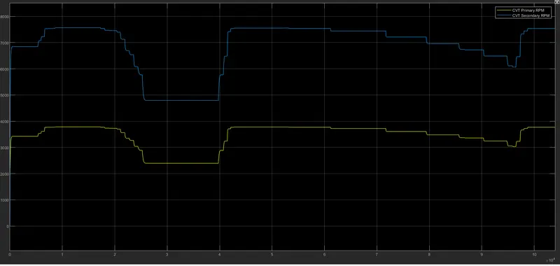
The CVT primary RPM is used to record the RPM from the engine and CVT secondary RPM records the RPM/output RPM of the CVT block
Simple Gear:
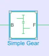
This block represents a fixed-ratio gear or gearbox. No inertia or compliance is modeled in this block. You can optionally include gear meshing and viscous bearing losses.
Connections B (base) and F (follower) are mechanical rotational conserving ports connecting CVT and vehicle bodies, Simple Gear block represents a gearbox that constrains the connected driveline axes of the base gear, B, and the follower gear, F, to corotating with a fixed ratio that we specify. the follower axis rotates in the same or opposite direction as the base axis.
Vehicle Body:
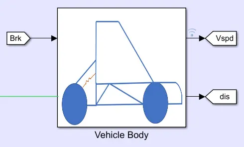
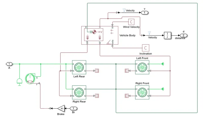
The above vehicle body is designed for all-terrain vehicles.
The rare wheels are powered by an engine followed by CVT and gearbox, the front wheels are connected to a rotational base, hence the all-terrain vehicle is RWD.
the vehicle body represents a two-axle vehicle body in longitudinal motion. The block accounts for body mass, aerodynamic drag, road incline, and weight distribution between axles due to acceleration and road profile. The vehicle can have the same or a different number of wheels on each axle. Optionally include pitch and suspension dynamics or additional variable mass and inertia. The vehicle does not move vertically relative to the ground.
Connection H is the mechanical translational conserving port associated with the horizontal motion of the vehicle body. The resulting traction motion developed by tires should be connected to this port. Connections V, NF, and NR are physical signal output ports for vehicle velocity and front and rear normal wheel forces. Wheel forces are considered positive if acting downwards. Connections W and beta are physical signal input ports corresponding to headwind speed and road inclination angle, respectively.
Solver configuration:
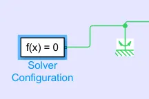
Each physical network represented by a connected Simscape™ block diagram requires solver settings information for simulation. The Solver Configuration block specifies the solver parameters that your model needs before you can begin the simulation.
Working:
Initially, Torque is fed to the Generic engine, the generic engine performs internal combustion and produces rotational motion to the engine shaft at port F.
The Port F is connected to an engine sensor to record the engine performance due to the variation in torque.
The CVT has inputs connected to the engine shaft and CVT-ratio
The port F(engine shaft) is connected with CVT via the engine sensor.
CVT-ratio block is connected to CVT.
The CVT works with a primary and secondary pully, each pulley connected via a chain belt. The pully can move to increase or decrease the belt diameter to change gear ratios, allow for quick shifting into the needed ratio for increased power, and boost fuel economy.
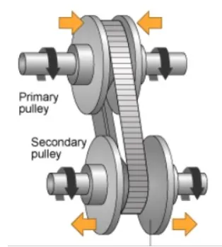
The primary pulley is connected to the engine shaft and the secondary pulley is connected to the gearbox.
Sensors are placed in between primary and secondary pully to record the motion.
The gearbox is connected with the vehicle's body to move the vehicle.
The performance of the vehicle body is recorded in Vspd.
The given model has 5-cases as listed below.
- BAJA AVT Model without a dashboard.
- BAJA AVT Model with the dashboard.
- BAJA AVT Model without dashboard (data written from signal builder to worksheet)
- BAJA ATV model using lookup table without a dashboard.
- BAJA ATV model using a lookup table with the dashboard.
Case 1:
BAJA AVT Model without a dashboard.
In this model, all inputs are pre-defined and can't be varied during the run time.
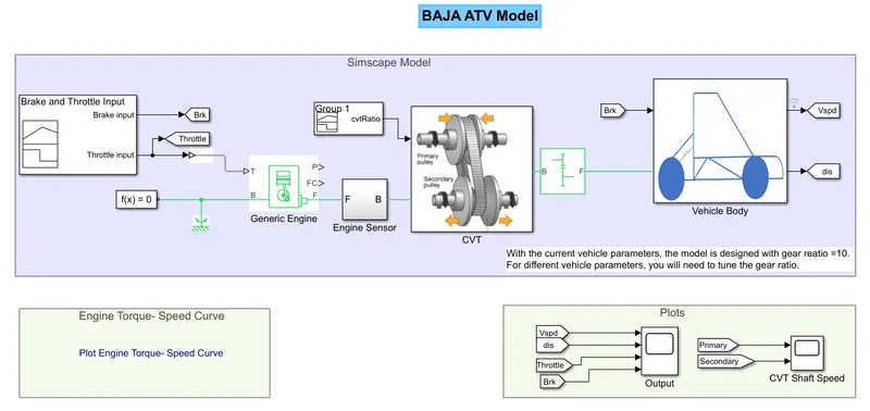
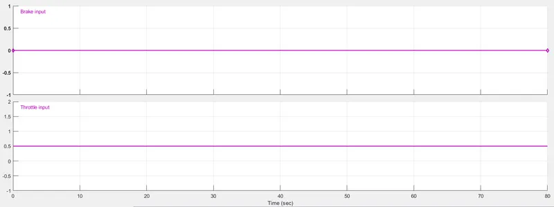
The torque and break are fed to the engine with help of signal builder blocks, in the above circuit, the Break input is '0' and torque is kept constant at 0.5, the input is as shown below.
The input CVT-ratio is also fed to the system with the help of a signal builder, the input is as shown below.
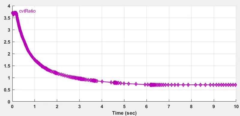
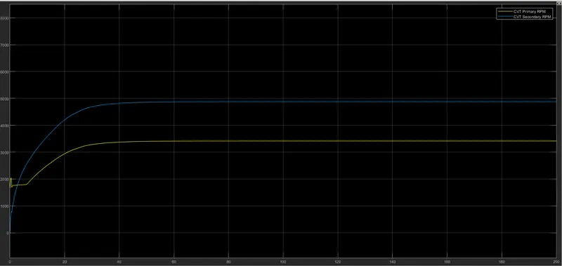
The engine produces constant rotational motion to the engine shaft with is connected to the CVT, the CVT produces rotational motion depending on the CVT ration
The output power will be as shown in the below graph.
Output:
The input and output of CVT.
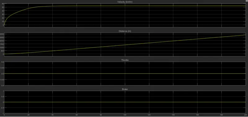
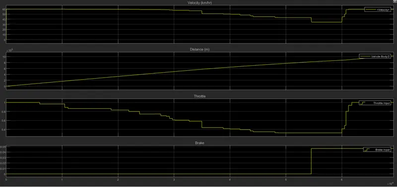
The below graph contains Velocity, distance, Throttle, and break
Case 2:
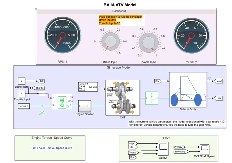
BAJA AVT Model with the dashboard.
In this model, all inputs are user-defined and can be varied during the run time using the dashboard components.
Working:
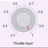
The above model works similarly to the previous model, the only difference is, we can give input throttle and apply break using the dashboard during simulation using the arrow mark in the below diagram, we can vary the throttle between 0 to 1.
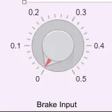
we can vary the break input between 0 to 0.5
The input CVT-ratio is also fed to the system with the help of a signal builder, the input is as shown below.
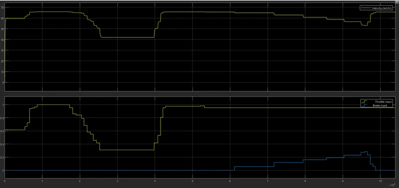
The Speed of the vehicle increase with the increase in input throttle and decreases with an increase in the break.
Graphs:
The input and output of CVT.

The below graph contains Velocity, distance, Throttle, and break
Case 3:
BAJA AVT Model without dashboard (data written from signal builder to worksheet)
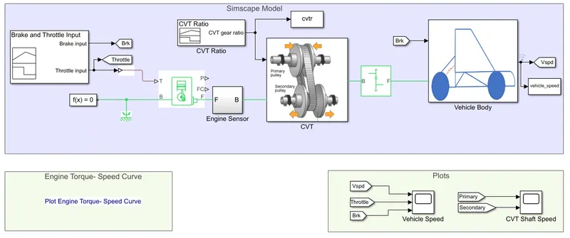
This case is similar to case1, all inputs are pre-defined and can't be varied during the run time.
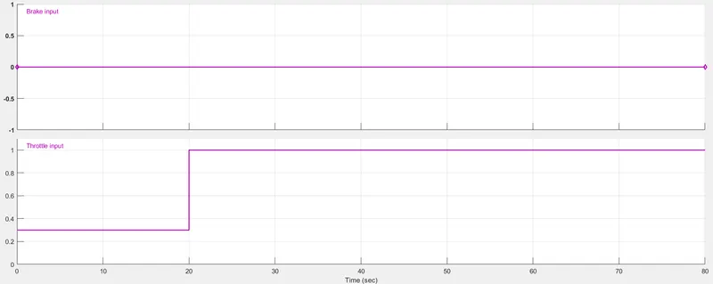
The torque and break are fed to the engine with the help of signal builder blocks, in the above circuit, the Break input is '0' and torque is kept constant at 0.5, the input is as shown below.
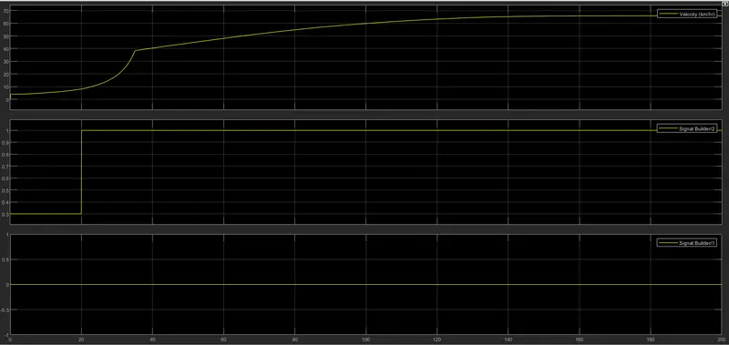
The torque rises from '0.3' to '1' after is 20sec.
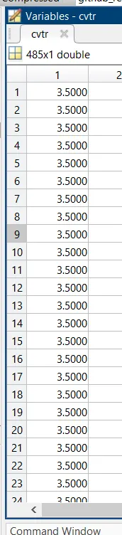
The input CVT ratio is also fed to the system with the help of a signal builder.
The signal builder input is also connected to a worksheet to collect the data in the local worksheet as shown in the above figure.
Data is written in the MATLAB base workspace and the data is not available until the simulation is stopped or paused.
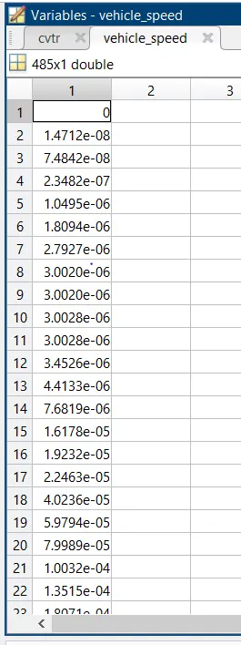
Similarly, the vehicle speed is also fed to a worksheet with the connection as shown in the above figure.
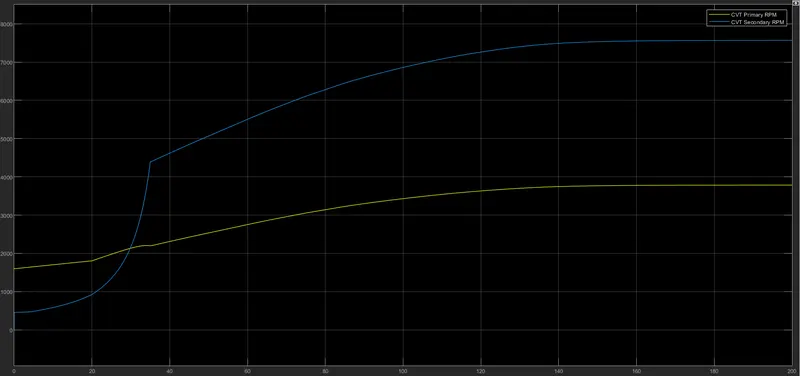
Graph:
The input and output of CVT.
The below graph contains Velocity, Throttle, and break
Case 4:
BAJA ATV model using lookup table without a dashboard.
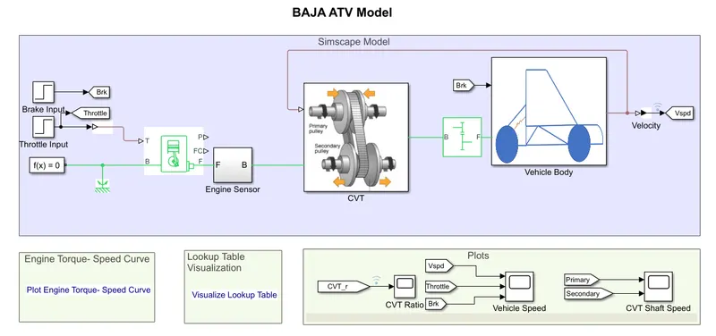
The working of this model is similar to the previous case.
The throttle and brake inputs are given using step blocks.
The CVT ratio port is connected to the output of the vehicle body as shown in the figure, ie speed.
The current output of the CVT-ratio followed by the CVT block depends on the previous output vehicle body (velocity).
Graph:
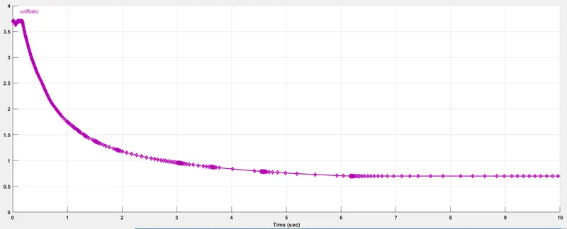
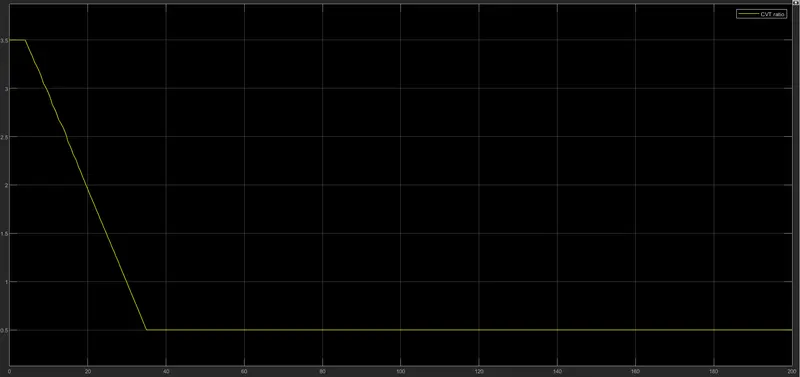
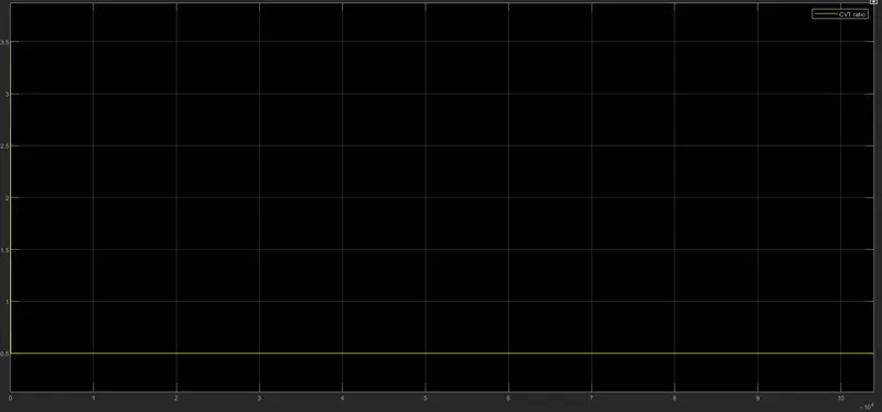
The below graph shows the CVT radio.
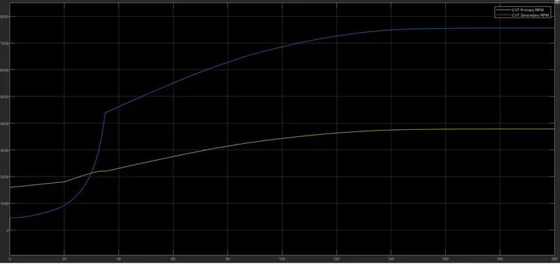
The below contains the input and output of CVT.
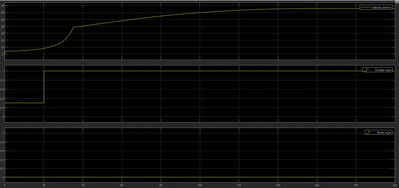
The below graph contains Velocity, throttle, and breaks.
Case5:
BAJA ATV model using a lookup table with the dashboard.
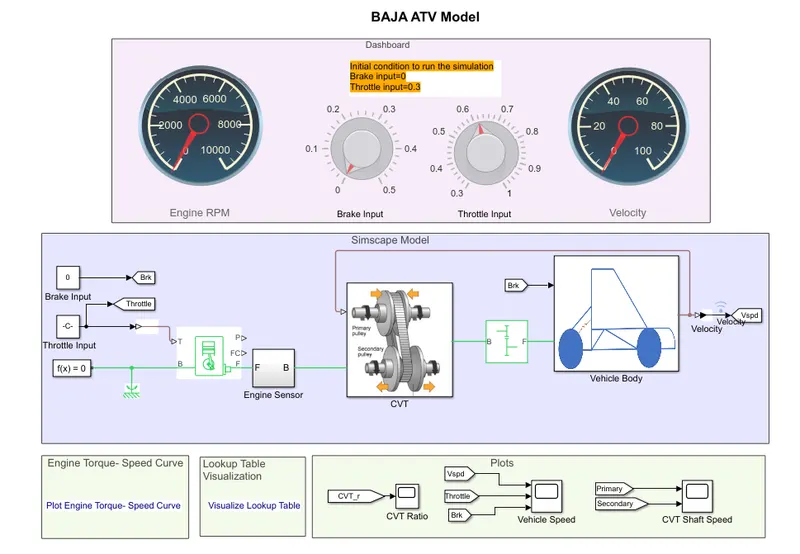
The working of this model is similar to case-2.
The only difference is, we can give input throttle and apply break using the dashboard during simulation, using the arrow mark in the below diagram we can vary the throttle between 0 to 1.
we can vary the break input between 0 to 0.5
The CVT ratio port is connected to the output of the vehicle body as shown in the figure, ie speed.
Graph:
The below graph shows the CVT radio.
The below contains the input and output of CVT.
The below graph contains Velocity, throttle, and breaks.
Conclusion:
- As the throttle increases, the velocity increases hence the power of the vehicle also increases.
- whenever the brake input increases, the velocity decreases in terms decrease the speed and power of the vehicle, an increase in brake power decreases the engine efficiency and power.