Week-7 Challenge: DC Motor Control
1 A. Explain a MATLAB demo model named ‘Speed control of a DC motor using BJT H-bridge’.
B. Comment on the armature current shoot-up from the scope results.
C. Refer to the help section of ‘The Four-Quadrant Chopper DC Drive (DC7) block’. Compare it with the H-bridge mo
Solution:
A.
An H-bridge is a simple circuit that lets us control a DC motor to go backward or forward.
A DC motor spins either backward or forward, depending on how we connect the plus and the minus.
The circuit diagram is as shown below
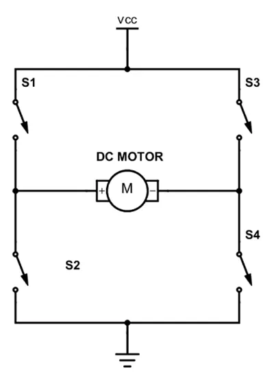
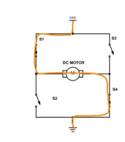
If you close switches 1 and 4, you have plus connected to the left side of the motor and minus to the other side. And the motor will start spinning in one direction.
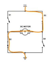
If you instead close switch 2 and 3, you have plus connected to the right side and minus to the left side. And the motor spins in the opposite direction.
The H-bridge consists of four BJT/Diode pairs (BJT simulated by IGBT models). Two transistors are switched simultaneously: Q1 and Q4 or Q2 and Q3. When Q1 and Q4 are fired, a positive voltage is applied to the motor, and diodes D2-D3 operate as free-wheeling diodes when Q1 and Q4 are switched off.
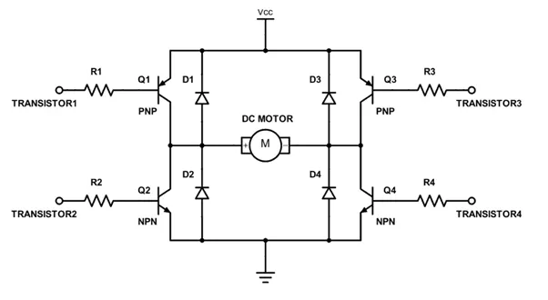
The diodes are placed parallel to the transistors as there are side effects of how a motor works are that the motor will also generate electrical energy. When we disable the transistors to stop running the motor, this energy needs to be released in some way.
If we use diodes in the reverse direction for the transistors, the motor will have a path for the current to take to release this energy. Without them, we will risk that the voltage rises and damages the transistors.
The Simulink model is as shown below.
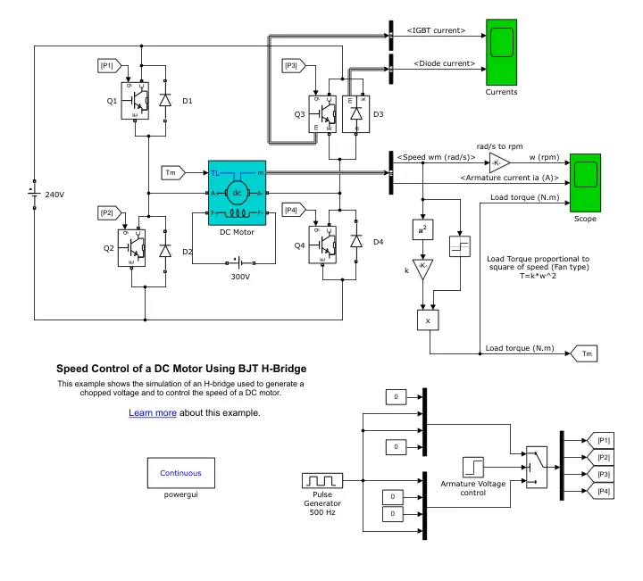
The DC motor uses the preset model (5 HP 24V 1750 rpm). It simulates a fan type load (where Load torque is proportional to the square of speed). The armature voltage can be varied from 0 to 240 V when the duty cycle (specified in the Pulse Generator block) is varied from 0 to 100%.
For the above case, 75% of 240 V is 180V.
The motor starts in the positive direction with a duty cycle of 75% (mean DC voltage of 180V) at t= 0.5 sec., the armature voltage is suddenly reversed and the motor runs in the negative direction.
Graph:
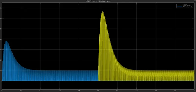
After simulating with default values, we have the below results.
The yellow legend indicates the current flowing through the transistor and the blue legend indicates the current generated by motors that are flowing through the diode.
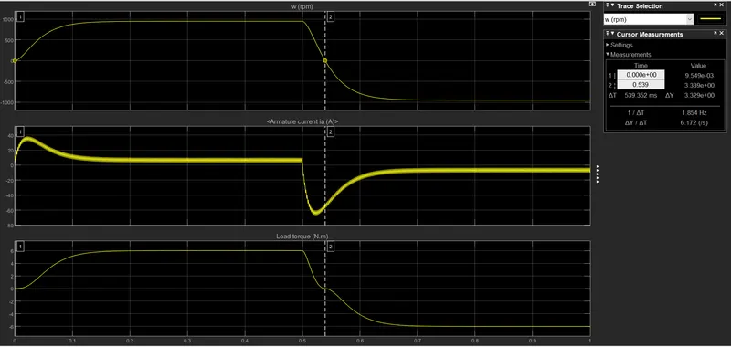
The below graph shows the change of director of DC motor from forwarding director to backward direction as it is designed, the motor is changing its direction at 0.5t with a duty cycle of 75%.
As we see the motor is slowing down immediately to run in the opposite direction.
The motor is working with a default value and is working as it is designed to work, we can also change parameters like duty cycle, input voltage, etc depending on the requirement.
B.
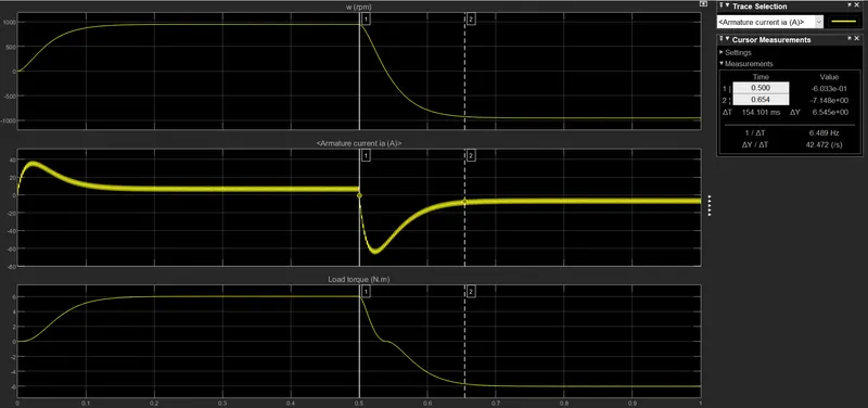
As we check, the armature current is increasing to achieve the maximum torque, after achieving the required torque the current decreases gradually and the torque remains constant.
When the motor changes its direction, the armature current goes high to reduce the torque in the current direction to zero, and then it achieves desired torque in the required direction and reduces and remains constant.
C.
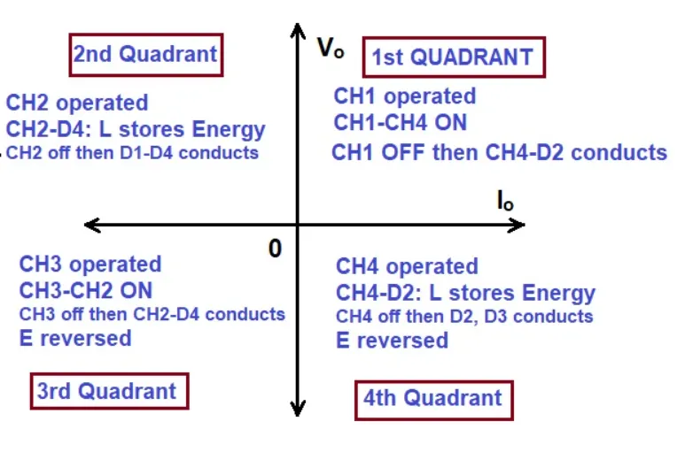
A four-quadrant chopper is a chopper that can be operated in all four quadrants. The power can flow either from source to load or load to source in this chopper. In the first quadrant, a Class-E chopper acts as a Step-down chopper whereas in the second quadrant it behaves as a Step-up chopper. This type of chopper is also known as Class-E or Type-E chopper. This article describes the working principle and operation of the Class-E chopper with the help of a circuit diagram.
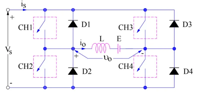
The operation of a four-quadrant chopper or Class-E chopper is summarized in the figure below.
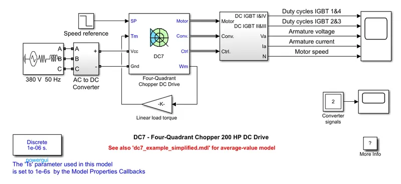
The Simulink model is as shown below.
The difference between H-bridge and four-Quadrant chopper is:
- Both H-bridge and four-Quadrant circuits are completely different.
- The input voltage in H-bridge is the DC source and in the DC chopper is the three-phase source, which is later converted from constant DC to variable DC voltage.
- Four quadrant choppers can operate in all 4-modes(forward and reverse monitoring, forward and reverse breaking), H-bridge can operate in two modes (forward and reverse monitoring).
- H-bridge is used to switch the polarity of motors, four-quadrant is used to switch the polarity and also to allow the current to flow out of load.
- Regenerative braking is possible in the four-quadrant chopper and not in an h-bridge model.
- The four-quadrant chopper gives more power efficiency than the H-bridge model.
///////////////////////////////////////////////////////////////////////////////////////////////////////////////////////////////////////////
2. Develop a 2-quadrant chopper using Simulink & explain the working of the same with the relevant results. (Refer to the article - Multiquadrant operation of the motor ).
Solution:
The Two-Quadrant Chopper block represents a two-quadrant controlled chopper for converting a fixed DC input to a variable DC output. The block contains two switching devices, two diodes, and a load.
article link - https://skill-lync.com/student-projects/multi-quadrant-operation-of-dc-motor-in-simulink
The chopper permits a change in the polarity of terminal voltage keeping the direction of current constant. In the below figure CH1and CH2 are the choppers working as electronic switches and D1 and D2 are the feedback diodes. Assuming continuous conduction, both CH1 and CH2 operate simultaneously.
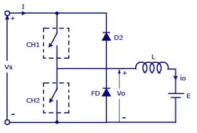
When the chopper CH1 is on the current flow from source to load. The inductor stores. when CH1 If turned off the freewheeling diode starts conducting and the output voltage Vo = Vs. the direction of the load current io will be reversed. The current io will be flowing towards the source. The load current will be negative when CH2 is on. The current completes its path through the diode d2.
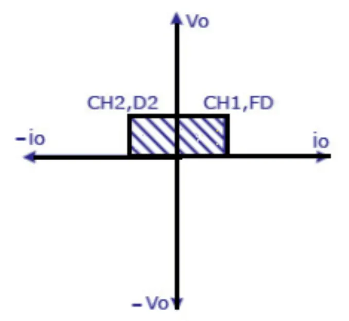
Both the switch never turn on at the same time because this will cause a short circuit. At the output, there is a freewheeling diode so the voltage is always positive. When chopper-CH2 (or switch 2) is turned on then the voltage is zero and when chopper 1 is turn on then the output voltage Vo=Vs.
We have created a Simulink model of the two-quadrant chopper, please find the model below.
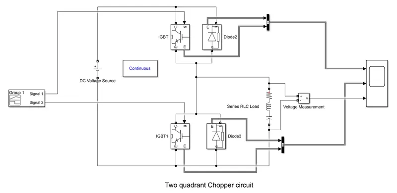
We have made use of IGBT as a Switch, IGBT is a unidirectional device, meaning it can only switch current in the “forward direction”, that is from Collector to Emitter
An insulated-gate bipolar transistor (IGBT) is a three-terminal power semiconductor device primarily used as an electronic switch, which, as it was developed, came to combine high efficiency and fast switching.
We have made use of a signal builder block to control the gates of both IGBT's i.e - the gate of IGBT-1 will be 'off' for 3-sec and On for the remaining amount of time, The gate of IGBT-2 will be 'On' for 3-sec and off for the remaining amount of time.
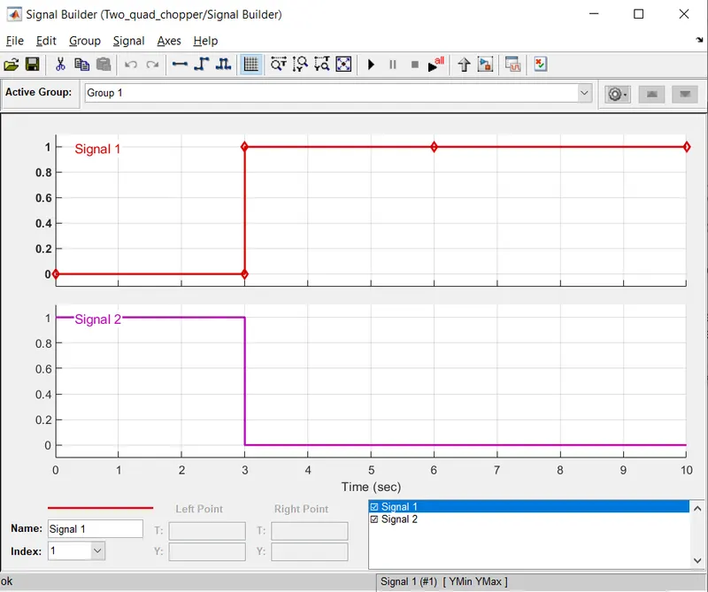
Signal 1 to IGBT-1
Signal 2 to IGBT-2
Graph:
The below graph shows the details of current and voltage flowing in IGBT-1, IGBT-2, diode1, and diode2.
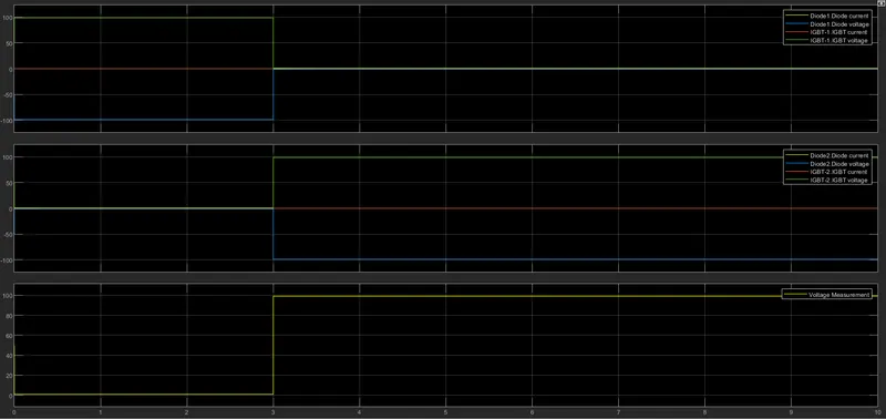
Attached Simulink file for reference.
///////////////////////////////////////////////////////////////////////////////////////////////////////////////////////////////////////////
3. Explain in a brief the operation of the BLDC motor.
Solution:
A brushless DC motor (known as BLDC) is a permanent magnet synchronous electric motor which is driven by direct current (DC) electricity and it accomplishes an electronically controlled commutation system (commutation is the process of producing rotational torque in the motor by changing phase currents through it at appropriate times) instead of a mechanical commutation system. BLDC motors are also referred to as trapezoidal permanent magnet motors.
BLDC motor works on the principle similar to that of a conventional DC motor, i.e., the Lorentz force law which states that whenever a current-carrying conductor is placed in a magnetic field it experiences a force. As a consequence of the reaction force, the magnet will experience an equal and opposite force. In the case of, BLDC motor, the current-carrying conductor is stationary while the permanent magnet moves.
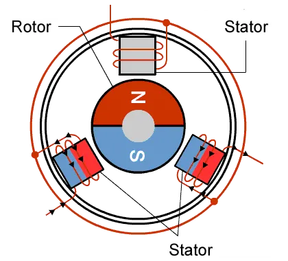
When the stator coils are electrically switched by a supply source, it becomes an electromagnet and starts producing the uniform field in the air gap. Though the source of supply is DC, switching makes to generates an AC voltage waveform with a trapezoidal shape. Due to the force of interaction between the electromagnet stator and the permanent magnet rotor, the rotor continues to rotate.
Consider the figure below in which the motor stator is excited based on different switching states. With the switching of windings as High and Low signals, corresponding winding energized as North and South poles. The permanent magnet rotor with North and South poles aligns with stator poles causing the motor to rotate.
Observe that the motor produces torque because of the development of attraction forces (when North-South or South-North alignment) and repulsion forces (when North-North or South-South alignment). In this way motor moves in a clockwise direction.