Week -2
Q1.Make a Simulink model of Doorbell using solenoid block
Solution:
Aim:
To Simulate a Simulink model of Doorbell using a Solenoid Block with the below conditions:
- when the switch is closed the electromagnet receives electrical power from the battery and pulls the metal arm to hit the bell producing sound.
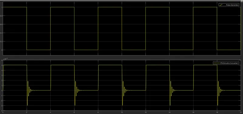
- Create a situation where the switch is closed for 2 seconds and then released. Observe the physical movement of the plunger.
Circuit:
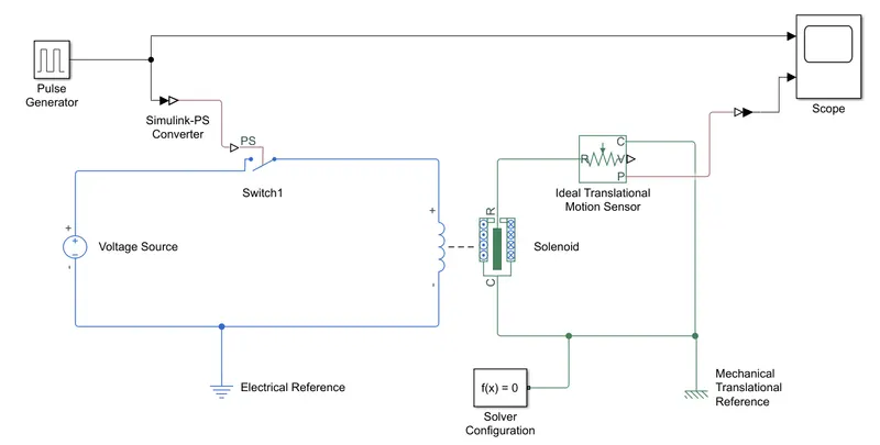
Components/Blocks in the system:
- Pulse generator
- Simulink to PS converter
- electrical switch
- Voltage source
- electrical references(ground)
- Solenoid
- ideal Transnational motion sensor
- Mechanical Transnational reference
- Solver configuration
- PS to Simulink converter
- Scope
- A Voltage source with input 50v is applied across the circuit with the frequency of 0hz.
- An electrical switch that is controlled by an external physical signal is used in the circuit. If the external physical signal PS is greater than the threshold, then the switch is closed otherwise, the switch is open.
- The external physical signal is generated by a pulse generator - used to generate pulse depending on the requirement i.e in the above case pulse generator is used to generate PS signals every 4s ( high for 2s and low of 2s).
- Since the switch's an input/external physical signal port that takes only Physical signal(PS), we have used Simulink to PS converter to convert the Simulink signal from the pulse generator to physical signals(PS).
- Electrical systems are connected to electrical reference(ground) and mechanical systems are connected to mechanical reference(Ground) as shown in the circuit.
- Each physical network must be connected to exactly one Solver Configuration block hence we need to connect the solver configuration to the circuit.
- The Solenoid block converts the electrical voltage across the circuit to linear mechanical motion by generating a magnetic field - when voltage is applied across the circuit, the coil in the Solenoid block generated a magnetic field due to which the port R moves away from the port C/Port R moves towards Port C, this creates a linear motion in the circuit.
- To capture the motion in the Solenoid block we have connected the Ideal Transnational motion sensor to sense the changes.
- The output from the ideal Transnational motion sensor is PS signals whereas the Scope is designed to view outputs of Simulink signal we have used PS to Simulink convert to convert the signals and connected as shown in the circuit.
Working:
The pulse generator generates PS signals every 4s i.e the switch is ON for 2s and OFF for 2s.
There are 2 cases:
Case 1:
When the switch is ON, the circuit is closed hence voltage is supplied across the circuit.
When the voltage is supplied to Solenoid, the coil creates a magnetic field due to which port R moves away from port C.
Case 2:
When the switch is OFF, the coil is disconnected with a voltage source, and the magnetic field decreases due to which Port R moves towards port C.
Graph:
Conclusion:
The system is working as per the requirements mentioned above, the parameters in the above circuits can be altered depending on the requirements.
Attached Simulink file for references.
///////////////////////////////////////////////////////////////////////////////////////////////////////////////////////////////////////////
Q2.Use a thermistor to sense the temperature of a heater & turn on or turn off the fan as per the below conditions:
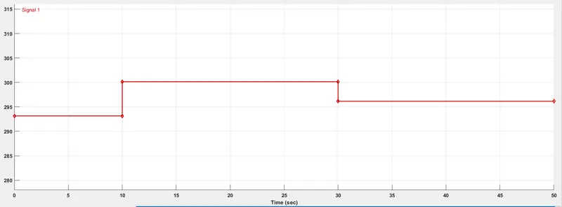
- Temperature source: 20 °C from 0 to 10 seconds, 27 °C from 10 to 30 seconds, 23 °C from 30 to 50 seconds
- Fan conditions: ON if the temperature above 25 °C, OFF otherwise
Solution:
Aim: Design a model Using a thermistor to sense the temperature of a heater & turn on or turn off the fan as per the below conditions:
- Temperature source: 20 °C from 0 to 10 seconds, 27 °C from 10 to 30 seconds, 23 °C from 30 to 50 seconds
- Fan conditions: ON if the temperature above 25 °C, OFF otherwise
Circuit:
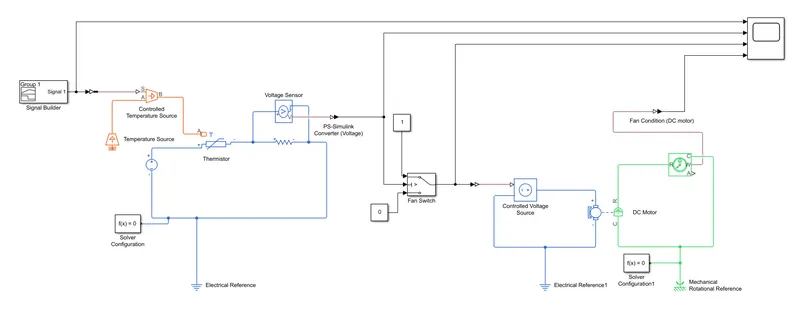
Components/Blocks in the system:
- Signal builder
- Controlled temperature source
- Temperature source
- Thermistor
- Voltage source
- Resistor
- Voltage sensor
- PS to Simulink converter
- Constant block
- Switch
- Simulink to PS converter
- Controlled voltage source
- DC motor
- Ideal rotational motion sensor
- Electrical references
- Mechanical rotational references
- Scope
- The Signal Builder block is used to build signals depending on the requirement, in this case, we have conditions set temperature 20 °C for 0 to 10 seconds, 27 °C from 10 to 30 seconds, 23 °C from 30 to 50 seconds.
-
Degree Celsius(°C) Kelvin(K) 20 °C 293.15K 23 °C 296.15K 27 °C 300K - The controlled temperature source controls the flow of temperature across the circuit, the ideal energy source in a thermal network that can maintain a controlled temperature difference regardless of the heat flow rate. The temperature difference is set by the physical signal port S.
- A thermistor is a resistance thermometer or a resistor whose resistance is dependent on temperature. the voltage flows across the circuit depends on the temperature around the thermistor.
- The ideal voltage sensor is a device that converts voltage measured between any electrical connections into a physical signal proportional to the voltage.
- A Voltage source with input 50v is applied across the circuit with the frequency of 0hz.
- A resistor is connected to measure the voltage change in the circuit followed by the thermistor as shown in the circuit.
- A switch(Controlled) is used to pass logic 1 and logic 0 depending on the threshold voltage.
- The controlled Voltage source is powerful enough to maintain the specified voltage at its output regardless of the current passing through it. The output voltage is V = Vs, where Vs is the numerical value presented at the physical signal port.
- A DC-Motor is used as a Fan in the circuit.
- An ideal Rotational Motion Sensor is used to sense the actions of DC-Motor.
- Each physical network must be connected to exactly one Solver Configuration block hence we need to connect the solver configuration to the circuit.
Working:
- The Temperature source is used to maintain a constant absolute temperature at the port regardless of the heat flow rate.
- The Signal builder sends input signals to a controlled source depends on its internal signal design.
- The controlled Temperature source limits the heat flow depending on the input signals from the Signal builder.
- The thermistor senses the change in temperature and allows voltage to flow across the circuit, if the temperature increases the voltage across the circuit increases, please refer to the graph for references.
- The voltage sensor measures the change in voltage across the resistor.
- The output voltage from the voltage sensor is connected to the condition port of the switch (If the given condition is passing then the Switch turns ON, otherwise OFF). As per the conditions above, the Fan should switch ON when the temperature is above 25 °C, OFF otherwise.
- In the above process, we already have the output voltages from the thermistor, we need to check the output of the thermistor at 25 °C, the same output is set as a condition to the switch to turn ON, for the above case the output of the thermistor at 25 °C is 12.35V hence the switch is designed to turn ON by setting the threshold voltage to 12.35V when the thermistor output is more than 12.35V the Switch is ON and OFF otherwise.
- Constant output 1 is connected to Switch ON and constant output 0 is connected to switch OFF as shown in the circuit.
Case 1: Switch = ON
The logic-1 is fed to a Controlled voltage source, the circuit becomes closed and voltage will be supplied to DC Motar hence the Fan is switch ON.
Case 2: Switch = OFF
The Logic-0 is fed to a Controlled voltage source, the circuit becomes open and voltage will not be supplied to DC-Motor hence the Fan is Switch OFF.
Graph:
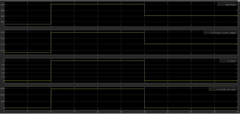
The system is working as per the requirement mentioned above, the parameters in the above circuits can be altered depending on the requirements.
Attached Simulink file for references.