Project-1: Powertrain for aircraft in runways
Part A:
1. Search and list out the total weight of various types of aircraft.
Solution:
The aircraft gross weight (also known as the all-up weight and abbreviated AUW) is the total aircraft weight at any moment during the flight or ground operation.
An aircraft's gross weight will decrease during a flight due to fuel and oil consumption. An aircraft's gross weight may also vary during a flight due to payload dropping or in-flight refueling.
At the moment of releasing its brakes, the gross weight of an aircraft is equal to its takeoff weight. During the flight, an aircraft's gross weight is referred to as the en-route weight or in-flight weight.
MTOW = Maximum take-off weight, MLW = Maximum landing weight, TOR = Take-off run (SL, ISA+15°, MTOW), LR = Landing run (SL, ISA+15°, MLW).
| Type | MTOW [kg] | MLW [tonnes] | TOR [m] | LR [m] | ICAO category | FAA category |
| Antonov An-225 | 6,40,000 | 591.7 | 3500 | Heavy | Super | |
| Scaled Composites Model 351 Stratolaunch | 5,89,670 | 3660 | Heavy | Super | ||
| Airbus A380-800[1][2][3] | 5,75,000 | 394 | 3100 | 1930 | Super | Super |
| Boeing 747-8F | 4,47,700 | 346.091 | 3100 | 1800 | Heavy | Heavy |
| Boeing 747-8 | 4,43,613 | 306.175 | 3100 | Heavy | Heavy | |
| Boeing 747-400ER | 4,12,770 | 295.742 | 3090 | Heavy | Heavy | |
| Antonov An-124-100M | 4,05,060 | 330 | 2520 | 900 | Heavy | Heavy |
| Boeing 747-400 | 3,96,900 | 295.742 | 3018 | 2179 | Heavy | Heavy |
| Lockheed C-5 Galaxy[4][5][6] | 3,81,000 | 288.417 | 2530 | 1494 | Heavy | Heavy |
| Boeing 747-200[7] | 3,77,840 | 285.7 | 3338 | 2109 | Heavy | Heavy |
| Boeing 747-300[7] | 3,77,840 | 260.32 | 3222 | 1905 | Heavy | Heavy |
| Airbus A340-500[8] | 3,71,950 | 240 | 3050 | 2010 | Heavy | Heavy |
| Airbus A340-600[8] | 3,67,400 | 256 | 3100 | 2100 | Heavy | Heavy |
| Boeing 777F | 3,47,800 | 260.816 | 2830 | Heavy | Heavy | |
| Airbus A330-900 | 3,52,000 | 251.5 | 3100 | Heavy | Heavy | |
| Boeing 777-300ER | 3,51,800 | 251.29 | 3100 | Heavy | Heavy | |
| Boeing 777-200LR | 3,47,450 | 223.168 | 3000 | Heavy | Heavy | |
| Boeing 747-100[7] | 3,40,200 | 265.3 | Heavy | Heavy | ||
| Airbus A350-1000 | 3,08,000 | 233.5 | Heavy | Heavy | ||
| Boeing 777-300 | 2,99,370 | 237.683 | 3380 | Heavy | Heavy | |
| Boeing 777-200ER | 2,97,550 | 213 | 3380 | 1550 | Heavy | Heavy |
| Airbus A340-300[8][9] | 2,76,700 | 190 | 3000 | 1926 | Heavy | Heavy |
| McDonnell Douglas MD-11 | 2,73,300 | 185 | 2990 | 1890 | Heavy | Heavy |
| Airbus A350-900 | 2,70,000 | 175 | 2670 | 1860 | Heavy | Heavy |
| Ilyushin Il-96M | 2,70,000 | 195.04 | 3115 | 2118 | Heavy | Heavy |
| McDonnell Douglas DC-10 | 2,56,280 | 183 | 2990 | 1890 | Heavy | Heavy |
| Boeing 787-9[10] | 2,54,000 | 192.777 | 2900 | Heavy | Heavy | |
| Boeing 787-10[10] | 2,54,000 | 201.849 | Heavy | Heavy | ||
| Airbus A340-200[8][11] | 2,53,500 | 181 | 2990 | Heavy | Heavy | |
| Ilyushin IL-96-300 | 2,50,000 | 175 | 2600 | 1980 | Heavy | Heavy |
| Airbus A330-300[12][13] | 2,42,000 | 185 | 2500 | 1750 | Heavy | Heavy |
| Airbus A330-200[12][13] | 2,42,000 | 180 | 2220 | 1750 | Heavy | Heavy |
| Lockheed L-1011-500 | 2,31,300 | 166.92 | 2636 | Heavy | Heavy | |
| Boeing 787-8[10] | 2,28,000 | 172.365 | 3300 | 1695 | Heavy | Heavy |
| Lockheed L-1011-200 | 2,11,400 | Heavy | Heavy | |||
| Ilyushin IL-86 | 2,08,000 | 175 | Heavy | Heavy | ||
| Boeing 767-400ER | 2,04,000 | 158.758 | 3414 | Heavy | Heavy | |
| Airbus A300-600R[14] | 1,92,000 | 140 | 2385 | 1555 | Heavy | Heavy |
| Boeing 767-300ER | 1,87,000 | 136.08 | 2713 | 1676 | Heavy | Heavy |
| Concorde | 1,85,000 | 111.1 | 3440 | 2220 | Heavy | Heavy |
| Airbus A300-600[14] | 1,63,000 | 138 | 2324 | 1536 | Heavy | Heavy |
| Boeing 767-300 | 1,59,000 | 136.078 | 2713 | 1676 | Heavy | Heavy |
| Airbus A310-300[14] | 1,57,000 | 124 | 2290 | 1490 | Heavy | Heavy |
| Vickers VC10 | 1,52,000 | 151.9 | Heavy | Heavy | ||
| Boeing 707-320B[15] | 1,51,000 | 97.5 | Heavy | Heavy | ||
| Boeing 707-320C[15] | 1,51,000 | 112.1 | Heavy | Heavy | ||
| Douglas DC-8-61 | 1,47,000 | Heavy | Heavy | |||
| Airbus A310-200[14] | 1,42,000 | 123 | 1860 | 1480 | Heavy | Heavy |
| Airbus A400M | 1,41,000 | 122 | 980 | 770 | Heavy | Heavy |
| Douglas DC-8-32 | 1,40,000 | Heavy | Heavy | |||
| Douglas DC-8-51 | 1,25,000 | Medium | Large | |||
| Boeing 757-300 | 1,24,000 | 101.6 | 2550 | 1750 | Medium | Large |
| Boeing 707-120B[15] | 1,17,000 | 86.3 | Medium | Large | ||
| Boeing 757-200 | 1,16,000 | 89.9 | 2347 | 1555 | Medium | Large |
| Boeing 720B[16] | 1,06,000 | 79.5 | Medium | Large | ||
| Boeing 720[16] | 1,04,000 | 79.5 | Medium | Large | ||
| Tupolev Tu-154M | 1,04,000 | 80 | Medium | Large | ||
| Tupolev Tu-204SM | 1,04,000 | 87.5 | 2250 | Medium | Large | |
| Convair 880 | 87,500 | Medium | Large | |||
| Boeing 737-900 | 85,000 | 66.36 | 2500 | 1704 | Medium | Large |
| Boeing 737-900ER | 85,000 | 71.35 | 2804 | 1829 | Medium | Large |
| Boeing 727-200 Advanced[17] | 84,000 | 70.1 | Medium | Large | ||
| Airbus A321-100[18] | 83,000 | 77.8 | 2200 | 1540 | Medium | Large |
| Boeing 737-800 | 79,000 | 65.32 | 2308 | 1634 | Medium | Large |
| Boeing 727-200[17] | 78,000 | 68.1 | Medium | Large | ||
| McDonnell-Douglas MD-83 | 73,000 | 63.28 | Medium | Large | ||
| Boeing 727-100[17] | 72,500 | 62.4 | Medium | Large | ||
| Boeing 727-100C[17] | 72,500 | 62.4 | Medium | Large | ||
| McDonnell-Douglas MD-90-30 | 71,000 | 64.41 | 2165 | 1520 | Medium | Large |
| de Havilland Comet 4 | 70,700 | Medium | Large | |||
| Boeing 737-700 | 70,000 | 58.06 | 1921 | 1415 | Medium | Large |
| Airbus A320-100[18] | 68,000 | 66 | 1955 | 1490 | Medium | Large |
| Boeing 737-400 | 68,000 | 54.9 | 2540 | 1540 | Medium | Large |
| de Havilland Comet 3 | 68,000 | Medium | Large | |||
| Boeing 377 | 67,000 | Medium | Large | |||
| Boeing 737-600 | 66,000 | 54.66 | 1796 | 1340 | Medium | Large |
| Airbus A220-300 | 65,000 | 57.61 | 1890 | 1494 | Medium | Large |
| Hawker Siddeley Trident 2E | 65,000 | Medium | Large | |||
| Airbus A319[18] | 64,000 | 62.5 | 1850 | 1470 | Medium | Large |
| Boeing 737-300 | 63,000 | 51.7 | 1939 | 1396 | Medium | Large |
| Boeing 737-500 | 60,000 | 49.9 | 1832 | 1360 | Medium | Large |
| Airbus A220-100 | 59,000 | 50.8 | 1463 | 1356 | Medium | Large |
| Airbus A318[18] | 59,000 | 57.5 | 1375 | 1340 | Medium | Large |
| Boeing 717-200HGW | 55,000 | 47.174 | 1950 | Medium | Large | |
| Douglas DC-7 | 55,000 | Medium | Large | |||
| de Havilland Comet 2 | 54,000 | Medium | Large | |||
| Boeing 717-200BGW | 50,000 | 46.265 | 1950 | Medium | Large | |
| de Havilland Comet 1 | 50,000 | Medium | Large | |||
| Douglas DC-6A | 48,600 | Medium | Large | |||
| Douglas DC-6B | 48,500 | Medium | Large | |||
| Embraer 190[19] | 48,000 | 43 | 2056 | 1323 | Medium | Large |
| Caravelle III | 46,000 | Medium | Large | |||
| Fokker 100 | 46,000 | 39.95 | 1621 | 1350 | Medium | Large |
| Douglas DC-6 | 44,000 | Medium | Large | |||
| Avro RJ-85 | 42,000 | 36.74 | Medium | Large | ||
| Handley Page Hermes | 39,000 | Medium | Large | |||
| Embraer 175[20] | 37,500 | 32.8 | 2244 | 1304 | Medium | Large |
| Bombardier CRJ900[21] | 36,500 | 33.345 | 1778 | 1596 | Medium | Large |
| Embraer 170[22] | 36,000 | 32.8 | 1644 | 1274 | Medium | Large |
| Bombardier CRJ700 | 33,000 | 30.39 | 1564 | 1478 | Medium | Large |
| Douglas DC-4 | 33,000 | Medium | Large | |||
| Vickers Viscount 800 | 30,400 | Medium | Large | |||
| Bombardier Q400 | 28,000 | 28.01 | 1219 | 1295 | Medium | Large |
| Bombardier CRJ200 | 23,000 | 21.319 | 1918 | 1479 | Medium | Large |
| ATR 72-600 | 22,800 | 22.35 | 1333 | 914 | Medium | Large |
| Saab 2000 | 22,800 | 21.5 | 1300 | Medium | Large | |
| Embraer ERJ 145 | 22,000 | 19.3 | 2270 | 1380 | Medium | Large |
| ATR 42-500 | 18,600 | 18.3 | 1165 | 1126 | Medium | Small |
| Saab 340 | 13,150 | 12.93 | 1300 | 1030 | Medium | Small |
| Embraer 120 Brasilia | 11,500 | 11.25 | 1560 | 1380 | Medium | Small |
| BAe Jetstream 41 | 10,890 | 10.57 | 1493 | 826 | Medium | Small |
| Learjet 75[23] | 9,752 | 8.709 | 1353 | 811 | Medium | Small |
| Pilatus PC-24[24] | 8,300 | 7.665 | 893 | 724 | Medium | Small |
| Embraer Phenom 300[25] | 8,150 | 7.65 | 956 | 677 | Medium | Small |
| Beechcraft 1900D | 7,765 | 7.605 | 1036 | 853 | Medium | Small |
| Cessna Citation CJ4[26] | 7,761 | 7.103 | 1039 | 896 | Medium | Small |
| de Havilland Hercules | 7,000 | Medium | Small | |||
| Embraer Phenom 100 | 4,800 | 4.43 | 975 | 741 | Light | Small |
////////////////////////////////////////////////////////////////////////////////////////////////////////////////////////////////////////////////////////////////
2. Is there any difference between ground speed and airspeed?
Solution:
When it comes to Airplane, there are two different types of speed – ground speed and airspeed.
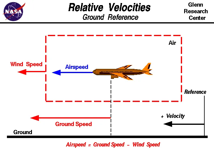
The Ground speed is the airplane’s speed relative to the surface of the Earth and Airspeed is the true airspeed – is its speed relative to the air it is flying in.
True airspeed is simply the speed at which an aircraft is moving relative to the air it is flying in. As such, it’s also the speed at which the air is flowing around the aircraft’s wings.
On the other hand, Ground speed is the aircraft’s speed relative to the ground. please note that it's horizontal rather than vertical speed – an aircraft climbing completely vertically would have a ground speed of zero.
In other words, while airspeed is what determines whether there is enough airflow around an aircraft to make it fly, ground speed is what determines how fast an aircraft will get to its destination.
Airspeed is the vector difference between the ground speed and the wind speed. On a perfectly still day, the airspeed is equal to the ground speed. But if the wind is blowing in the same direction that the aircraft is moving, the airspeed will be less than the ground speed.
Airspeed = Ground speed - Wind speed
//////////////////////////////////////////////////////////////////////////////////////////////////////////////////////////////
3. Why is it not recommended to use aircraft engine power to move it on the ground at the Airport?
Solution:
There are three main reasons why is it not recommended to use aircraft engine power to move it on the ground at the Airport.
High Fuel Consumption:
Taxiing (rarely spelled taxying) is the movement of an aircraft on the ground, under its own power, in contrast to towing or pushback where the aircraft is moved by a tug, the Airplane primary engines are usually jet engines and they consume a high amount of jet fuel to start and move the vehicle while still on the ground, Fuel is the biggest expense of an Airlines and to reduce that expense it is not recommended to use aircraft engine power to move it on the ground at the Airport
Wear and tear on the engine:
By starting an engine power creates a cycle on an engine. Engines are often inspected according to the number of cycles the engine has on it, or sometimes by the hours. This gives you a hint as to why an engine wears. To be more specific it’s the temperature change in the engine. Sometimes an engine over temps and you can quickly have a problem. But if an engine behaves you can have it on the wing for many years before it needs an overhaul. That is because engineering has developed it to stand up to that high temperature without incident. Sometimes engines operate in a harsh environment and are susceptible to erosion and/or corrosion which can be another factor.
Second, tear on an engine. In general, for an engine ‘tear’ is a specific description of a blade. So we going to include Nick's dents and any other damage in the engine. This is damage due to impact. Most common is a foreign object coming in the inlet and into the core of the engine and striking a blade.
Unnecessary noise caused by an Airplane engine:
High engine thrust during maintenance activity can cause considerable damage to airplanes and other elements in the airport environment.
Aircraft engines are the major source of noise and can exceed 140 decibels (dB) during takeoff. While airborne, the main sources of noise are the engines and the high-speed turbulence over the fuselage. There are health consequences of elevated sound levels. Airport noise has been linked to high blood pressure.
An example of this problem occurred after an airplane arrived at its final destination with a log entry indicating the flight crew had experienced anomalous engine operation. The subsequent evaluation resulted in the replacement of an engine control component, followed by an engine test and trim run to verify proper engine operation. The airplane was positioned on an asphalt pad adjacent to a taxiway, with the paved surface extending from the wingtips aft to the empennage. During the high-power portion of the test run, a 20- by 20-ft (6.1- by 6.1-m) piece of the asphalt immediately aft of the engine detached and was lifted from the pad surface.
////////////////////////////////////////////////////////////////////////////////////////////////////////////////////////////////////////////////////////////////////////////////////////////////////////////////////////////////////////////
4. How an aircraft is pushed to the runway when it's ready to take off?
Solution:
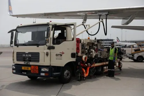
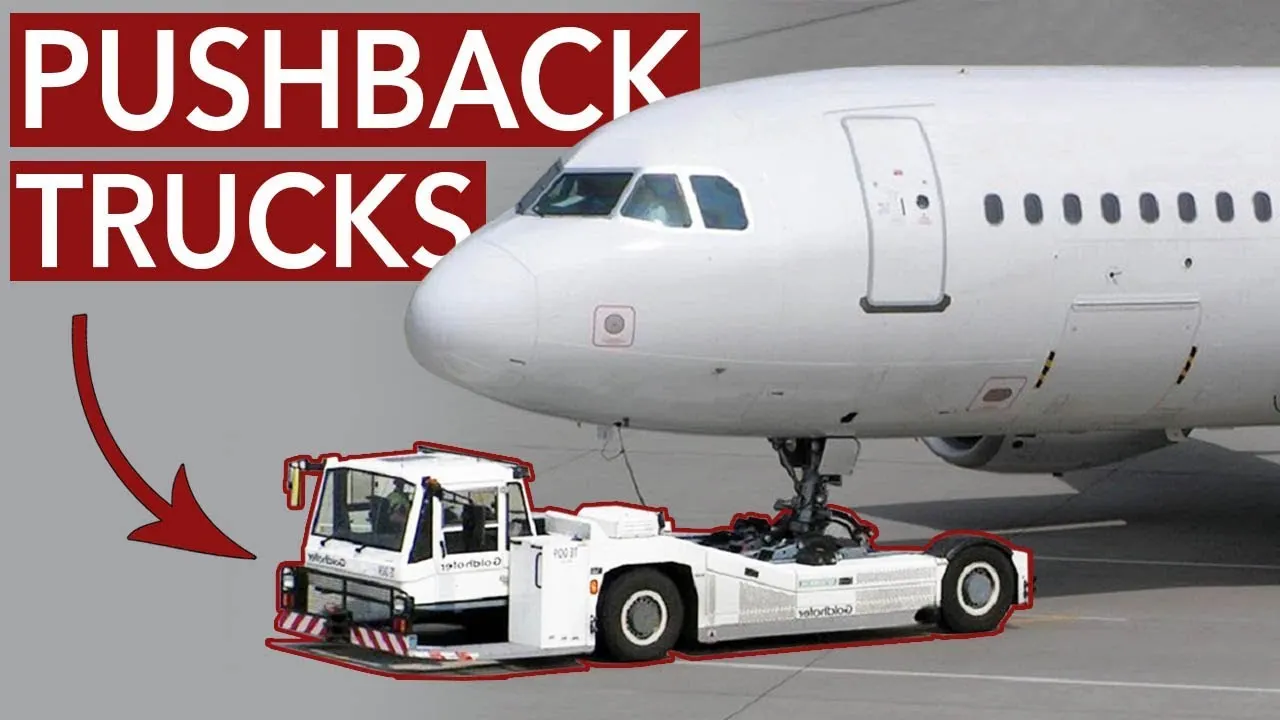
An Aircraft pushback truck is used to reverses the aircraft into a taxiing position, pushing it with a towbar attached to the nose-wheel strut. Or, in the most modern versions, by actually lifting the wheel. The aircraft taxis to the runway to depart at the agreed time.
A small vehicle is needed to push the airplane backward away from the terminal building because even if a plane can reverse its thrust, it’s not always safe to hit the buildings with a jet blast. So the little trucks push the jets back away from the buildings, but after that, the plane can apply a small amount of engine power to roll forward.
They are looking out to make sure nothing will touch the aircraft. The whole idea is to avoid expensive crunching noises.
The philosophy is that both pilots are to monitor the taxi route and avoid being ‘heads down’ in the cockpit whilst taxiing. Common procedures that will be seen during the ground phase of the flight will therefore be:
- The Before Taxi/After Engine Start checklist being completed before commencing taxi.
- The taxi route being confirmed between both pilots.
- Crews that are unfamiliar with the airfield may take a relatively long period of time to check the cleared taxi route on the aerodrome charts before commencing taxi.
- Turning points, holding points, runways, and runway incursion hotspots are being verbally called out.
In keeping with this philosophy, it is, therefore, best practice for controllers to refrain from issuing any instructions when aircraft are approaching any such turning points or runways to avoid the pilots becoming distracted at those locations.
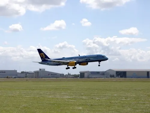
- The pilot parks the aircraft in exactly the right place. Usually with the help of an automatic system, but occasionally guided by a marshaller waving two paddles or wands. Dozens of handling personnel are already standing by to perform a whole range of tasks simultaneously.
- As soon as the aircraft is stationary and the engines are switched off, the priority is to disembark the passengers as quickly as possible. The apron handler places chocks in front of the wheels and connects the ground power. Meanwhile, the passenger bridge maneuvers up to the door, and a belt loader rolls up to the cargo hold. Luggage is unloaded and transferred to the terminal on baggage carts.
- Refueling begins, usually from a hydrant at the stand. A hose is attached to this from a special vehicle called a dispenser, with the other side connected to the fuel tank in the wing. Read more about refueling.
- Now it is time to service the aircraft. The caterer loads new meals and takes away the food waste and used cutlery and crockery. Other activities include draining the lavatories, replacing the headrest covers, removing rubbish, and distributing fresh blankets and in-flight magazines.
- A specialist team – or sometimes the crew themselves – cleans the cabin so that the new passengers board a pristine aircraft.
- Meanwhile, specialists from the airline conduct a technical check to make sure that the engines, wings, control surfaces, landing gear, instruments, doors, and other equipment are in full working order.
- The aircraft is now ready for baggage to be loaded for the next flight. This is a quick process, on average taking only 10-15 minutes. A little later the passengers start boarding. As soon as they are all in their seats, the door is closed and the pilot informs air traffic control that the flight is ready for departure.
- The apron handler removes the chocks. A so-called pushback truck reverses the aircraft into taxiing position, pushing it with a towbar attached to the nose-wheel strut. Or, in the most modern versions, by actually lifting the wheel. That speeds up coupling and decoupling.
- The aircraft taxis to the runway to depart at the agreed time.
- The pilot waits for permission to take off from air traffic control. This is possible once the departure route is clear. As soon as the go-ahead is received, the plane takes to the air at full power.
////////////////////////////////////////////////////////////////////////////////////////////////////////////////////////////////////////////////////////////////////////////////////////
5. Learn about take-off power, tire design, rolling resistance, tire pressure, brake forces when landing.
Solution:
Take off Power:
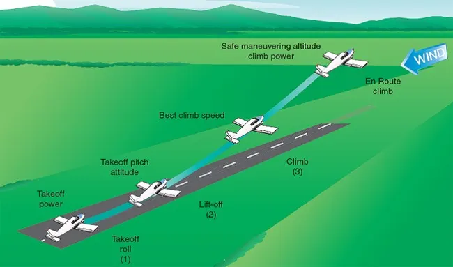
On take-off, to position the aircraft to a safe height away from terrain and obstacles (i.e. a flight path of maximum height and minimum ground distance desired), the engine thrust is set to a high ‘take-off power’ setting (although this is not necessarily full power) and the aircraft attitude is pitched up to maintain a specific speed (usually in the region of V2 + 15kts). Once the ‘safe height’ is reached the engine thrust can therefore be reduced to a more appropriate (i.e. efficient) setting and the aircraft flight path can be changed to a more appropriate (i.e. efficient) flight path.
Tyre Design:
Radial tires are the most modern design of aircraft tires. It is a design that is similar to that of car tires. Typically, the radial tire offers more landings per tread and lighter weight than a bias tire.
Carcass plies are used to form the tire. They are sometimes called casing plies. An aircraft tire is constructed for the purpose it serves.
- They support the weight of an aircraft while it is on the ground.
- It also provides the necessary traction for the braking and stopping of an airplane.
- Tyre also helps to absorb the shock of landing and provides cushioning for the roughness of takeoff, roll-out, and taxi operations.
Unlike an automobile or truck tire, it does not have to carry a load for a long period of continuous operation. However, an aircraft tire absorbs the high impact loads of landing, and also it’s operating at high speeds for a short time when required.
Rolling resistance:
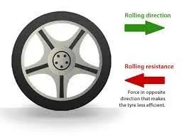
Tire rolling resistance is the energy that your vehicle needs to send to your tires to maintain movement at a consistent speed over a surface. In other words, it is the effort required to keep a tire rolling. ... Hysteresis is essentially the energy loss that occurs as a tire roll through its footprint.
Rolling resistance sometimes called rolling friction or rolling drag is the force resisting the motion when a body rolls on a surface. It is mainly caused by non-elastic effects; that is, not all the energy needed for deformation (or movement) of the wheel, roadbed, etc., is recovered when the pressure is removed.
As the tire comes in contact with the road, its shape change due to its compression, this compression causes part of the rubber tube and the casing of the tire to heat up. It also causes the tread on the outside of the tire to heat up as it comes in contact with the road. The tire with knobbly tread will have a lot more rolling resistance than a smooth tire because there will be more rubber being compressed and there will be more heat.
The force of rolling resistance does not change at high speed. However, because there is a lot more heat being produced at higher speeds, the engine needs to use more power to work against rolling resistance.
As the front tire touches the road, it takes a lot of force to squeeze the tire. this causes a backward force on the wheel. As the tire comes back to the road, there is a force pushing forwards on the wheel, but this force is not high, this is because of the internal friction in the tire.
Some factors that affect the rolling resistances are
- Mass of the vehicle
- Cornering
- Design of tire
- Road or track surface
Tyre pressure:
Aircraft tires generally operate at high pressures, up to 200 psi (14 bar; 1,400 kPa) for airliners, and even higher for business jets. The main landing gear on the Concorde was typically inflated to 232 psi (16.0 bar), whilst its tail bumper gear tires were as high as 294 psi (20.3 bar).
Tests of airliner aircraft tires have shown that they can sustain pressures of a maximum of 800 psi (55 bar; 5,500 kPa) before bursting.[citation needed] During the tests the tires have to be filled with water, to prevent the test room from being blown apart by the energy that would be released by gas when the tire bursts.
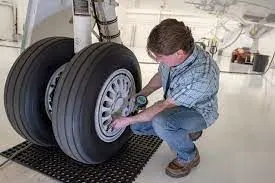
Aircraft tires are usually inflated with nitrogen to minimize expansion and contraction from extreme changes in ambient temperature and pressure experienced during flight. Dry nitrogen expands at the same rate as other dry atmospheric gases (normal air is about 80% nitrogen), but common compressed air sources may contain moisture, which increases the expansion rate with temperature.
The requirement that an inert gas, such as nitrogen, be used instead of air for inflation of tires on certain transport category airplanes was prompted by at least three cases in which the oxygen in air-filled tires had combined with volatile gases given off by a severely overheated tire and exploded upon reaching autoignition temperature. The use of inert gas for tire inflation eliminates the possibility of a tire explosion.
| Airplane | Operating weight(lbs) | Tire pressure (psi) |
| B727-200 | 185000 | 148 |
| B737-300 | 130000 | 195 |
| A319-100 | 145000 | 196 |
| B747-400 | 820000 | 200 |
| B767-300ER | 370000 | 190 |
| DC8-63 | 330000 | 194 |
| A300-B4 | 370000 | 205 |
Brake forces when landing:
Airplanes rely on a braking system to safely land on runways. At cruising altitude, most commercial airplanes fly at a speed of roughly 500 to 600 mph. When landing, however, they must reduce their speed. A typical 747, for instance, has a landing speed of about 160 to 170 mph. And upon touching the runway, airplanes must quickly brake until they come to a complete stop.
The breaking is applied parallel with the help of wing spoilers, Disc breaks, and reverse thrust.
Wing Spoilers :
Many airplanes use wing spoilers to assist with braking when landing. Spoilers are extendable flaps on the ends of an airplane’s wings. Pilots can raise the spoilers to decelerate the airplane as it approaches the runway. And even while on the runway, pilots will typically leave the wing spoilers raised. Raised wing spoilers create the drag, which essentially slows down the airplane so that it’s able to brake more quickly.
Disc Brakes :
In addition to wing spoilers, airplanes use disc brakes. Airplane disc brakes are similar to the braking system in automobiles. They consist of a pair of calipers that, when engaged, squeeze pads against the rotors of an airplane’s landing gear.
Disc brakes are designed to remain static at all times. In other words, they don’t rotate with the wheels of an airplane’s landing gear. As the wheels turn, the disc brakes will remain static and stationary. They are a vital component of an airplane’s braking system because they are designed to apply pressure to the airplane’s wheels. Disc brakes will squeeze the wheels, thereby slowing down the speed at which they spin. In turn, this reduces the speed of the airplane so that it can come to a complete stop on the runway.
Reverse Thrust :
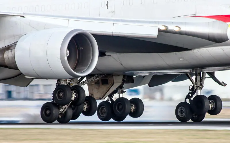
Finally, many jet airplanes use reverse thrust to assist with braking during landings. Reverse thrust is a feature in jet engine airplanes that involves the reversal of the engine's thrust. When flying, the thrust is projected out the rear of an airplane’s engines. When landing, however, pilots may use the reverse thrust feature. Reverse thrust changes the direction of the engine's thrust. Rather than projecting out the rear, the thrust will be projected out the front. This reversal of thrust provides deceleration that allows airplanes to slow down more quickly when landing.
///////////////////////////////////////////////////////////////////////////////////////////////////////////////////////////////////////////
Part B:
6.
A. With necessary assumptions, calculate the force and power required to push/pull an aircraft by a towing vehicle.
Solution:
To calculate the total forces acting on the vehicle and power required to push/pull an aircraft by a towing vehicle, we need parameters like Kerb Weight (kg), Payload (kg), Coefficient of rolling resistance, Air density (kg/m3), Width (m), Height (m), Drag coefficient and velocity
Let
- Coefficient of rolling resistance = 0.025
- Truck kerb mass = 30000 kg
- Payload mass = 20000 kg
- Air density = 1.25 kg/m^3
- Drag co-efficient of truck = 0.4
- Drag co-efficient of Airplane= 0.030
- Velocity = 20kmh = 5.55 m/s
- Frontal area = 1.225 m
The formula to calculate rolling resistance is
Frr = Coefficient of rolling resistance *total mass(m)*gravity(g)
Total mass = 50000 kg
Frr = 0.025*50000*9.8
Frr = 12250 N.
The formula to calculate aerodynamic force is
Fad = 1/2*air density*frontalarea*drag cofficient*velocity^2
Since we have both truck and airplane, we need to add both drag coefficients to get the exact aerodynamic force acting on the towing truck.
Fad = 1/2*1.25*1.225*(0.4+0.030)*5.55^2
Fad = 10.140 N
The formula to calculate Hill climbing force is
Fh = total mass*gravity*Sin(hill climbing angle)
Since the Airport flight parking area will have a flat surface with a 0-degree hill-climbing angle, we can neglect the hill-climbing force acting on the towing vehicle.
To calculate total tractive power
Fte = Frr + Fad+Fh
Fte = 12250 + 10.140
Fte = 12260.140 N
The total tractive force acting on vehicle is 12260.140 N
Total power can be calculated by using the below formula
P = Fte*v
where P = power, Fte = Total tractive force, v=Velocity
P = Fte*v
P = 12260.140*5.55
P = 68043.78122 w
The power required to push/pull an aircraft by a towing vehicle is 68,043.78122 w.
B. Develop the model for the calculated force and power using Simulink.
Solution:
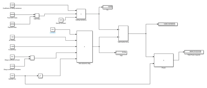
We need to make use of the above formulas to build the model for the calculated force and power using Simulink.
We have made use of constant block, multiplication block, and add a block to build the model.
We have made use of a display block to display the outputs.
The model is as shown below:
The formula to calculate rolling resistance is
Frr = Coefficient of rolling resistance *total mass(m)*gravity(g)
The formula to calculate aerodynamic force is
Fad = 1/2*air density*frontal area*drag coefficient*velocity^2
To calculate total tractive power
Fte = Frr + Fad
Total power can be calculated by using the below formula
P = Fte*v
The expected outputs are
Frr = 12250 N.
Fad = 10.140 N.
Fte = 12260.140 N
P = 68043.78122 w
All outputs are matching the expected output, hence the model is working properly.
Attached Matlab file for reference.
//////////////////////////////////////////////////////////////////////////////////////////////////////////////////////////////////////////////////////////////////////////
7.
A. Design an electric powertrain with the type of motor, its power rating, and energy required to fulfill aircraft towing application in Simulink. Estimate the duty cycle range to control the aircraft speed from zero to highest. Make all required assumptions. Prepare a table of assumed parameters. Draw a block diagram of the powertrain.
(Hint: DC7 Block)
B. Also, Design the parameters in an excel sheet.
Solution:
Lets consider the same values that are used previously to develop the electric power train of towing truck.
Assumed parameters:
Coefficient of rolling resistance = 0.025
Truck kerb mass = 30000 kg
Payload mass = 20000 kg
Air density = 1.25 kg/m^3
Drag co-efficient of truck = 0.4
Drag co-efficient of Airplane= 0.030
Velocity = 20kmh = 5.55 m/s
Frontal area = 1.225 m
The formula to calculate rolling resistance is
Frr = Coefficient of rolling resistance *total mass(m)*gravity(g)
Total mass = 50000 kg
Frr = 0.025*50000*9.8
Frr = 12250 N.
The formula to calculate aerodynamic force is
Fad = 1/2*air density*frontalarea*drag cofficient*velocity^2
Fad = 1/2*1.25*1.225*(0.4+0.030)*5.55^2
Fad = 10.140 N
Since the Airport flight parking area will have a flat surface with a 0-degree hill-climbing angle, we can neglect the hill-climbing force acting on the towing vehicle.
To calculate total tractive power
Fte = Frr + Fad+Fh
Fte = 12250 + 10.140
Fte = 12260.140 N
The total tractive force acting on vehicle is 12260.140 N
Total power can be calculated by using the below formula
P = Fte*v
P = 12260.140*5.55
P = 68043.78122 w
The power required to push/pull an aircraft by a towing vehicle is 68.0437 kwh
The Duty cycle is given by
Duty cycle = (output power/ input power)*100
Assuming input power of motor is 90 kw
Duty cycle = (output power/ input power)
Duty cycle = (68.0437/90)*100
Duty cycle = 0.756*100
Duty cycle = 75.6%
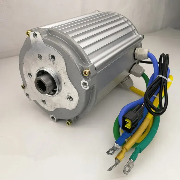
We can make use of both BLDC and induction motor to move the towing truck, in order to show the powertrain in simple manner we have made use of DC-Motor to represent the entire working of towing truck motor.
NEMA 17, 42mm 24v to 48v Brushless DC Motor
Rating:
12 volt, 24 volt, 2000 rpm 4000 rpm 8000 rpm high speed BLDC motor, 0.06Nm-0.25Nm (9Oz-in ~ 36Oz-in), 13 ~ 105 watts
|
MODEL |
GM42BLF | GM42BLF | GM42BLF | GM42BLF | GM42BLF | GM42BLF | GM42BLF | GM42BLF | GM42BLF | GM42BLF | GM42BLF | |
| 40-128-H | 60-113 | 60-123 | 60-130 | 40-240 | 60-240 | 80-240 | 100-240 | 40-220 | 60-214 | 60-270 | ||
| Number of pole | 8 pole | |||||||||||
| Number of phase | 3 phase | |||||||||||
| Rated voltage | Volt | 12 | 12 | 12 | 12 | 24 | 24 | 24 | 24 | 24 | 24 | 24 |
| Rated speed | RPM | 3000 | 1300 | 2300 | 3000 | 4000 | 4000 | 4000 | 4000 | 2000 | 1400 | 7000 |
| Rated torque | Oz-in | 8.9 | 17.7 | 17.7 | 17.7 | 8.9 | 17.7 | 26.9 | 36 | 8.9 | 17.7 | 17.7 |
| Nm | 0.063 | 0.125 | 0.125 | 0.125 | 0.063 | 0.125 | 0.19 | 0.25 | 0.063 | 0.125 | 0.125 | |
| Rated current | A | 2.4 | 2.5 | 4 | 5 | 1.8 | 3.5 | 5.2 | 6.6 | 0.9 | 1.3 | 6.2 |
| Rated power | Watt | 20 | 16 | 29 | 38 | 26 | 52 | 79 | 105 | 13 | 18 | 90 |
| Peak torque | Oz-in | 26.9 | 53.1 | 53.1 | 53.1 | 26.9 | 53.1 | 80.7 | 107 | 26.9 | 53.1 | 53.1 |
| Nm | 0.19 | 0.375 | 0.375 | 0.375 | 0.19 | 0.375 | 0.57 | 0.75 | 0.19 | 0.375 | 0.375 | |
| Peak current | A | 7.2 | 7 | 11 | 14 | 5.4 | 10.5 | 15.6 | 20 | 2.7 | 3.9 | 18.6 |
| Rotor inertia | g.c㎡ | 24 | 48 | 48 | 48 | 24 | 48 | 72 | 96 | 24 | 48 | 48 |
| Length L | mm | 40 | 60 | 60 | 60 | 40 | 60 | 80 | 100 | 40 | 60 | 60 |
| Weight | Kg | 0.33 | 0.45 | 0.45 | 0.45 | 0.33 | 0.45 | 0.65 | 0.8 | 0.33 | 0.45 | 0.45 |
Some models can be custom designed for 12V 24V 36V or 48V power supply, and the rated speed can be any number between 1000 rpm and 3000 rpm
We can choose any motor depending on the requirement.
We have made use of Buck converter as power converter to provide switching action to control the motor.
We have implemented the calculation of all forces inside the same model to make change in the parameter if necessary.
The Simulink model is as shown below.

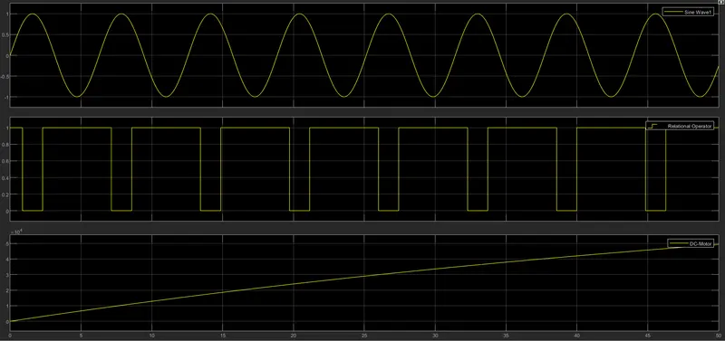
The output of the model is shown in the below graph.
The Buck converter is switching with the duty cycle of 75.6%, in the below graph the output from relational operator represent switching.
Sine wave is used as a references wave for supporting switching operation.
Attached simulink file for references
Designing the parameters in an excel sheet.
We can also used an excel sheet calculator to get the values of forces acting on the vehicle, the UI of excel is as shown below:
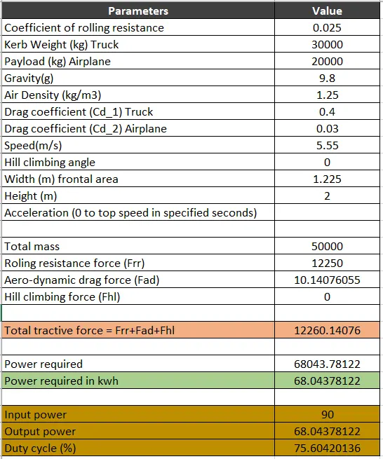
All outputs values form excel sheet are matching the outputs of manual calculation and from simulink model.
Attached excel file for references.
//////////////////////////////////////////////////////////////////////////////////////////////////////////////////////////////////////////