Week - 4
Q1.
Aim: To implement control logic of a “washing machine” using Stateflow as per given sequence:
- If the power supply is available, the system gets activated
- If the Water supply is not available, stop the process & indicate through LED
- Soaking time should be 200s followed by Washing time of 100s.
- Then rinsing happens for the next 20s & dryer runs for 50s
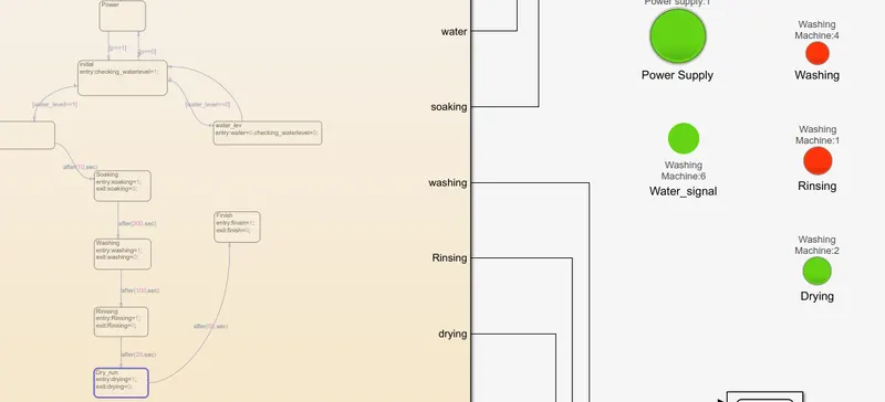
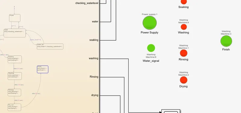
Circuit:
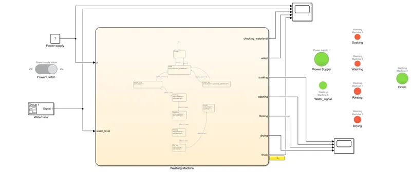
Chart Stateflow:
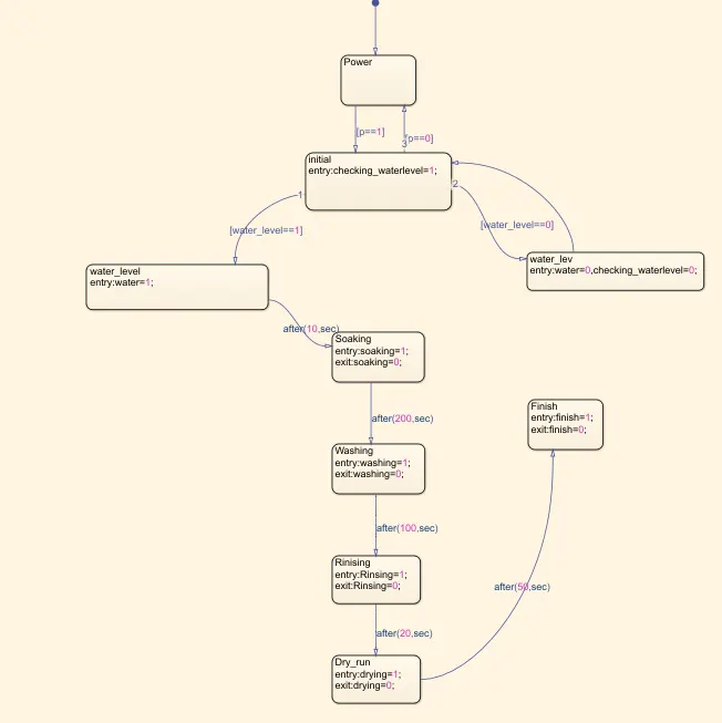
Working:
We have used a constant block with a slider switch to provide power supply input to the system, when the slider is ON the output of the constant block is '1', and '0' if it's Off.
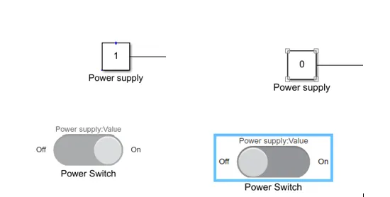
The washing machine switches "On" when the power supply(p) p==1.
After Switching 'ON', the machine checks the water level, if it's high it indicates with the lamp 'water signal' in green color and then moves to the next step.
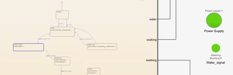
If it's low, it indicates with the lamp 'water signal' in red and checks the water status every 10s(in the loop) until water status becomes high.
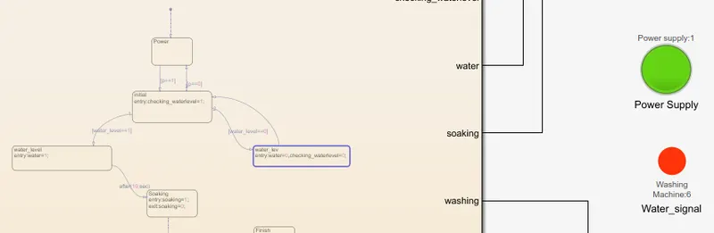
After checking the water status if the water status is high, the washing machine performs the below tasks for a scheduled amount of time.
The lamp color green indicated that the operation is in process and respectively.
Task 1: Soaking for 200sec, the washing machine performs this task for 200 sec and then moves to the next step.
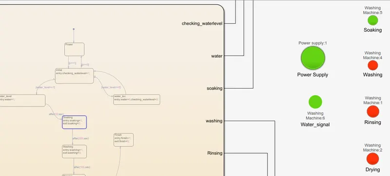
After 200s
Task 2: Washing for 100sec, the washing machine performs this task for 100 sec and then moves to the next step.
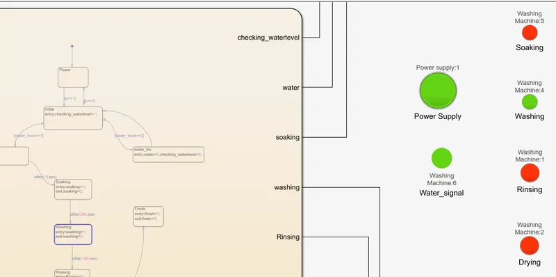
After 100sec
Task 3:Rinising for 20sec, the washing machine performs this task for 20 sec and then moves to the next step.
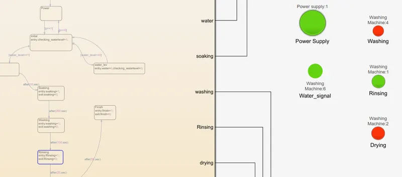
After 20 sec
Task 4:Drying for 50 sec, the washing machine performs this task for 50 sec and then moves to the next step.
After 50 sec.
After finishing all the above tasks the Finish lamp turns green indicating that the clothes are washed.
Graph:
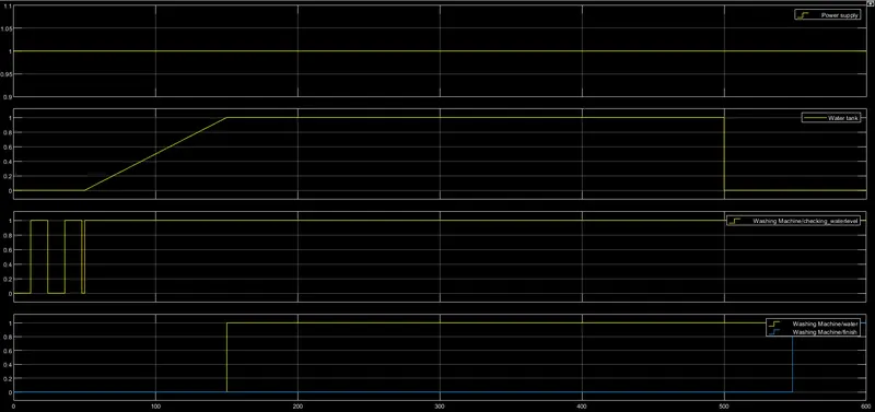
The below graph is for the power supply, water, water level, and finish button.
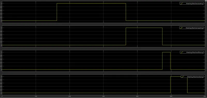
the below graph is for tasks performed by the washing machine like Soaking, Washing, Rinsing and drying.
Conclusion:
The washing is working as per the specification and the outputs are as expected.
Attached Simulink file for references.
Attached simulation video for references.
Q2.
Aim: To make a Simulink chart for the “Gear shift” logic as per below conditions:
Speed Range(kmph) Gear
0 to 15 1
16 to 25 2
26 to 40 3
41 to 60 4
Above 61 5
Give speed input while the simulation is running & display the gear number.
Circuit:
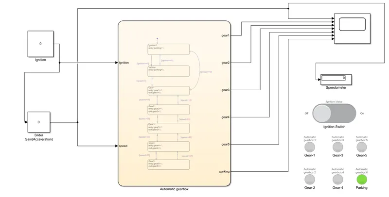
Chart Stateflow:
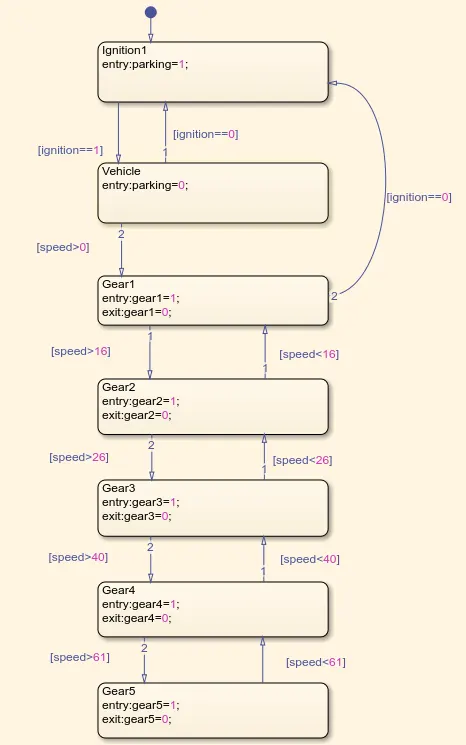
Working:
We have used a constant block with a slider switch to provide Ignition input to the system, when the slider is ON the output of the constant block is '1', and '0' if it's Off.
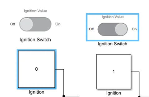
The vehicle turns 'ON' when the ignition switch is 'ON'.
We have used slider gain to provide speed inputs during the run time. The slider gain is designed to vary the speed from 0 to 100 Kmpl during simulation.
The Ignition switch is connected to slider gain as an external signal to turn ON the slider gain block as shown in the circuit.
We have connected the display to the slider gain block to check the variation of the speed in real-time.
The vehicle remains in a parking state when the ignition is OFF and vice versa, The lamp 'Parking', if it's 'Green' it indicates that the vehicle is in parking and 'Red' indicates that it is not in parking.
When a vehicle is turned 'ON', the gearbox shifts the gear depending on the Speed.
The Slider gain is used to vary the speed during simulation.
The lamp color, if it is in green it indicates that the gear is active.
Gear1: if the vehicle speed is between 0 to 15kmpl, the vehicle gear remains in 1st gear till the speed of the vehicle is more than 15kmpl.
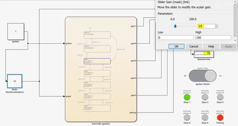
Gear2: if the vehicle speed is between 16 to 25kmpl, the vehicle gear remains in 2nd gear whenever the speed is between 16 to 25kmpl.
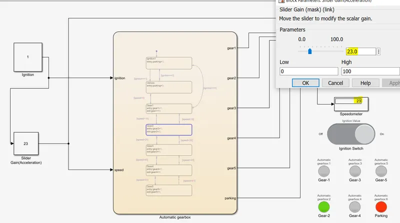
Gear3: if the vehicle speed is between 26 to 40kmpl, the vehicle gear remains in 3rd gear whenever the speed is between 26 to 40kmpl.
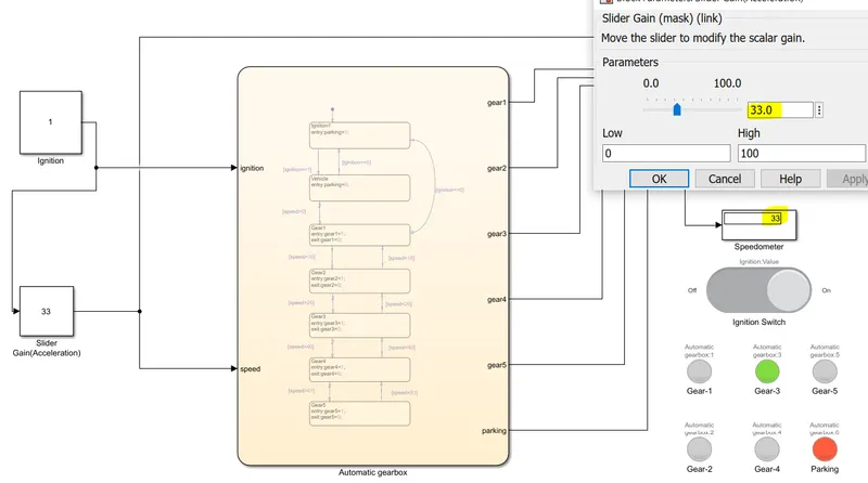
Gear4: if the vehicle speed is between 41 to 61kmpl, the vehicle gear remains in 4th gear whenever the speed is between 41 to 61kmpl.
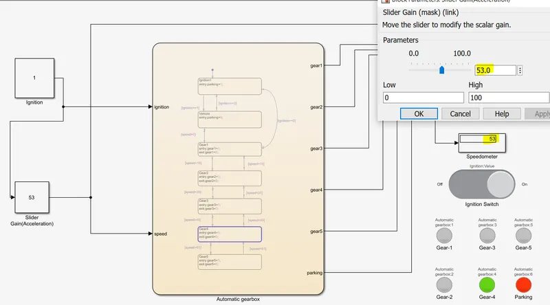
Gear5: if the vehicle speed is more than 61kmpl, the vehicle gear remains in 5th gear if the speed of the vehicle is more than 61kmpl.
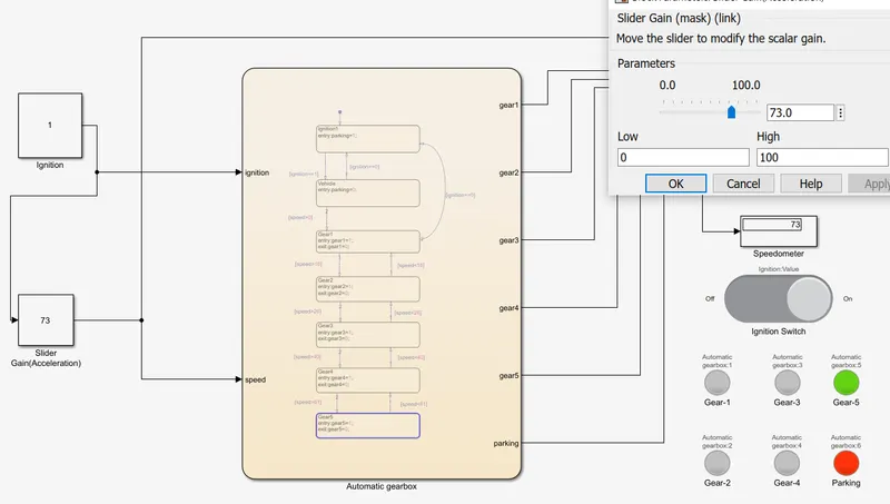
Whenever if the ignition is OFF in the circuit, the vehicle automatically decreases the gears and comes to Parking mode.
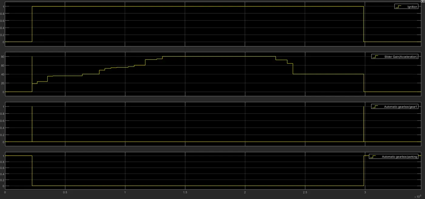
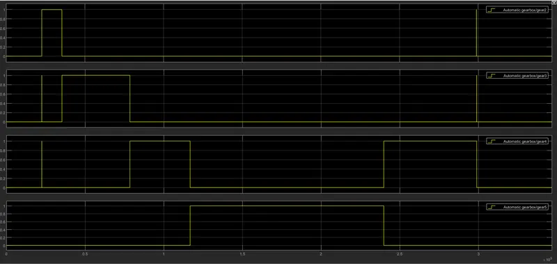
Graph:
The below graph is for Ignition, Slider gain(acceleration), gear1, and Parking
The below graph id for gear2,gear3,gear4, and gear5.
Conclusion:
The Automatic gearbox is working as per the specification and the outputs are as expected.
Attached Simulink file for references.
Attached simulation video for references.