Project 2 Thermal modeling of battery pack
AIM :
To simulate the thermal effect and compare life-cycle performance of a 10 cell series lithium ion battery model at various temperatures, charge and discharge rate using Matlab.
OBJECTIVES :
To create model containing 10 cells in series that are connected to a temperature source. This is done in order to study the behaviour of state of charge of the battery pack a different temperature.
INTRODUCTION :
A battery is used by discharging the current stored in it and again charging it for the next use. Chemical reactions take place in the battery in order to supply and receive the current. The effect of temperature on the battery is related to the chemical reactions and also the materials used in the battery cell. There is a relation between the rate of chemical reaction and the temperature of reaction, governed buy an equation call Arrhenius equation simply change in temperature can slow down or increase the rate of chemical reaction in the battery. Also due to change in temperature the conductivity of the ions of electrolyte and electrode is also changed. This effect of temperature on batteries are seen as reduced capacity, reduce charge and discharge rate, reduced state of charge, reduction in the life cycle etc. A typical air cooled battery is supplied with ambient air and temperature to cool the cell.in this type of cooling the inner cells are not called properly as the air cannot reach them.hence the inner cell is remain hot during loading.in order to validate this we are using a Matlab model of lithium ion battery and analysing the result.
MATLAB CODE :
clear all
Close all
Clc
F1 = xlsread(‘UDDS current profile (2).xlsx’)
Time = f1 (:,1);
Current = f1(:,2);
SIMULINK MODEL :
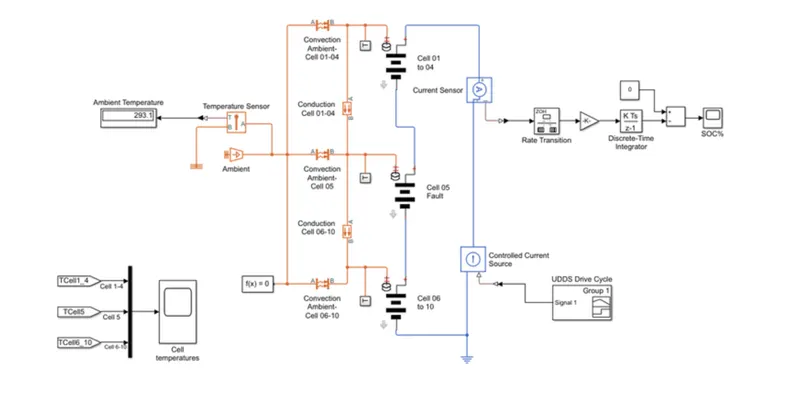
EXPLANATION :
Operating voltage of a battery pack of an electric vehicle can be varied by connecting several cells in series, which each cell adding to the total terminal voltage.parallel connection attends higher capacity for increased current standing as it cells adds to the total current handling. Some banks may have a combination of series and parallel connection. As we require a higher voltage battery pack for our model we are connecting the cells in Series. The cells are split in three groups: cell(1 to 4) cell 5 and cell(6 to 10) indicating the fault condition.
As we know the cell causes an imbalance especially in a serial configuration and a battery is only as strong as the weakest cell. In this model cell 5 is a weak cell causing an imbalance in the pack. It can be noted that a weak cell will cause a variation in SOC and we can know it by simulating this model. A polity cell could cause excessive heat and become a fire hazard for the battery pack.
Batteries generate heat during charge and discharge due to enthalpy changes, electro chemical polarisation and register heating inside the cell. Temperature variation inside the batteries can lead to any one temperature distribution which creates an even charge/discharge behaviour within the battery pack. Thermal runaway may occur in a cell or not properly control and possible to cause fire an explosion. For this reason, the need for a battery thermal management is necessary for a EV battery pack at its optimal performance.
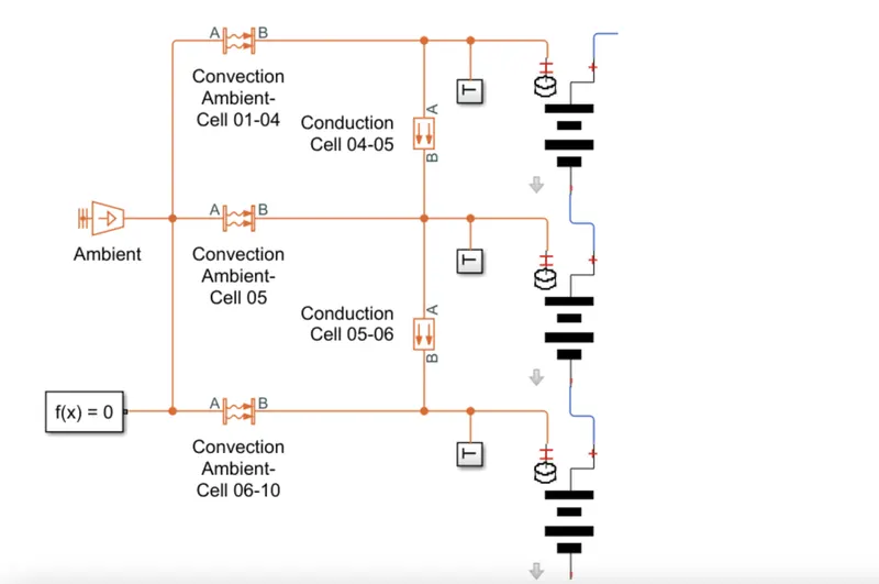
We have 10 lithium ion cells connected in series to a current source the temperature of each cell is sensed by a temperature sensor also a sensor is placed to check the ambient temperature. Convective heat transfer occurs between the cells for ambient temperature reference and conductor of heat transfer occurs between cells to check the actual cell temperature.
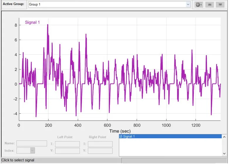
A UDDS drive cycle is implemented to know the behaviour of cell at different speeds and the associate of the entire pack is obtained.
The cells in series are divided into 3 groups cell(1 to 4) cell 5 and cell(6 to 10),
The cell 5 who is at fault condition.we are going to simulate and observe what is happening to the same temperature for each cell group and the SOC.
The UDDS drive cycle implemented for this model is as follows
Vehicle current Mode :
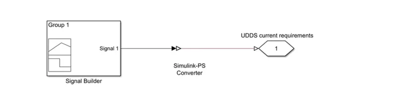
In vehicle current requirement subsystem block the signal builder Block used to apply UDDS current profile and send you link yes converter blog is used to convert the symbol in signal to a physical signal connection port to output the signal.
CELL 1 TO 5 :
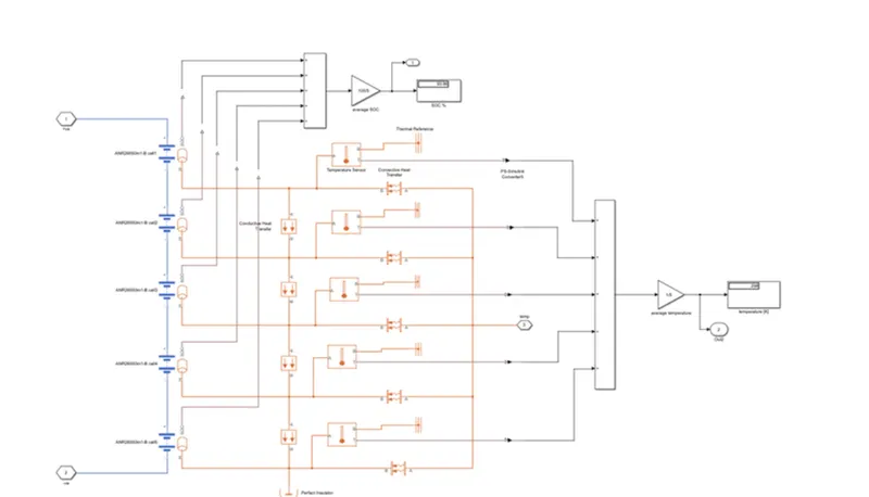
Here use five table battery based Block in which we put the data sheet value on it where we put the battery specification like 2.5 AH capacity, initial temperature value is 298K and this 5 cells are connected in series.
Also we use the conductor of heat transfer blogs in which we put the thermal conductivity as 401W/(K*m), area is 10m^2 and thickness 0.1m
We use the convective heat transfer blocks in which we put the heat transfer coefficient as 20W/(K*m) area is 10m^2 and one end of this block is connected to the thermal source and the other is connected to the particular cell. We also use perfect insulator. We also use temperature sensor to sense the temperature of cell and display the value in scope and dashboard, also its one end is connected to the thermal reference.
And SOC of every cell is also calculated by using add and didn't log and display the SOC value in % in display block.
CELL 6 :
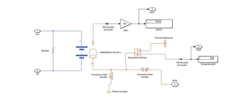
Here we use five table battery based Block in which we put the data sheet value on it where we put the battery specification like 2.5 AH capacity, initial temperature value is 298K and addition to that across the battery terminal we use the 5ohms resistor to show this is the faulty cell
Also we use the conductor of heat transfer blogs in which we put the thermal conductivity as 401W/(K*m), area is 10m^2 and thickness 0.1m
We use the convective heat transfer blocks in which we put the heat transfer coefficient as 20W/(K*m) area is 10m^2 and one end of this block is connected to the thermal source and the other is connected to the particular cell. We also use perfect insulator. We also use temperature sensor to sense the temperature of cell and display the value in scope and dashboard, also its one end is connected to the thermal reference.
And SOC of every cell is also calculated by using add and didn't log and display the SOC value in % in display block.
CELL 7 TO 10 :
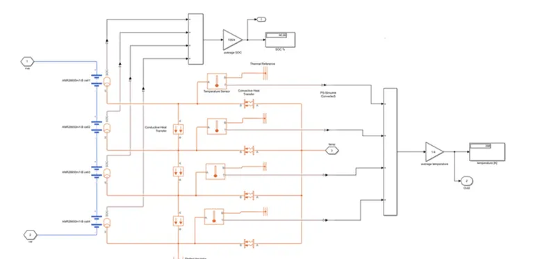
Here we use five table battery based Block in which we put the data sheet value on it where we put the battery specification like 2.5 AH capacity, initial temperature value is 298K and 4 cells are connected in series.
Also we use the conductor of heat transfer blogs in which we put the thermal conductivity as 401W/(K*m), area is 10m^2 and thickness 0.1m
We use the convective heat transfer block in which we put the heat transfer coefficient as 20W/(K*m) area is 10m^2 and one end of this block is connected to the thermal source and the other is connected to the particular cell. We also use perfect insulator. We also use temperature sensor to sense the temperature of cell and display the value in scope and dashboard, also its one end is connected to the thermal reference.
And SOC of every cell is also calculated by using add and didn't log and display the SOC value in % in display block.
RESULTS :
The SOC of cells
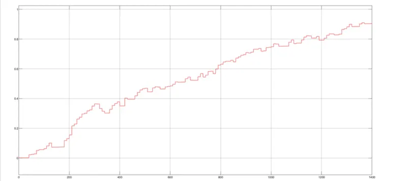
The SOC of the cells is increasing gradually from 0 to 0.9 as current is being supplied
The SOC is 90% at the end of the end of cycle
Cell temperatures for different cell groups :
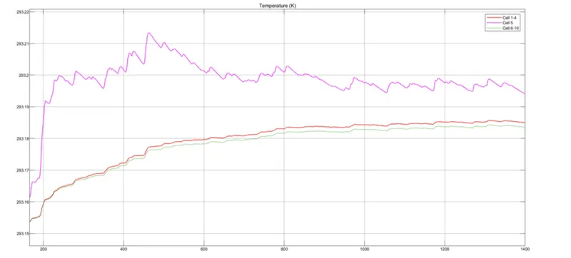
The cell temperature of cells(0 to 4) increasing gradually from 0 to 600 seconds and is stable from 600 to the end of the cycle. Hey Siri temperature for cells (6-10) is same as cells(0-4) with a slight larger value.
Since the cell 5 is at fault, hey Siri temperature increases suddenly and reduces after 600 seconds. This also affects the SOC as the SOC is varying after the cell temperature is increasing.
The temperature of all cell group is always higher than the ambient temperature during the cycle.
CONCLUSION :
we can conclude that when the cell is a fault condition it's temperature rises with time and causes an imbalance in the battery pack an affect the SOC of the pack.
What is the battery pack is not manage or the fault condition is not solved then it will lead to increased heating of the cell and will lead to a fire hazard.
The battery performance is highly affected by the fault in in the cell and continued charging and discharging will lead to the creation of the battery too soon.