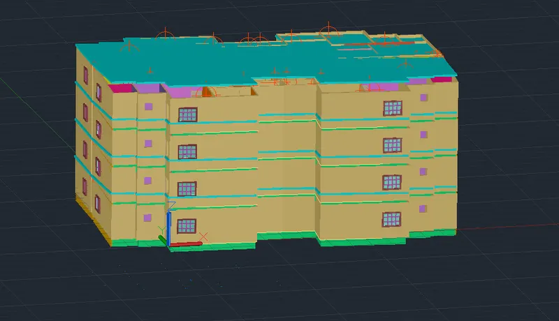
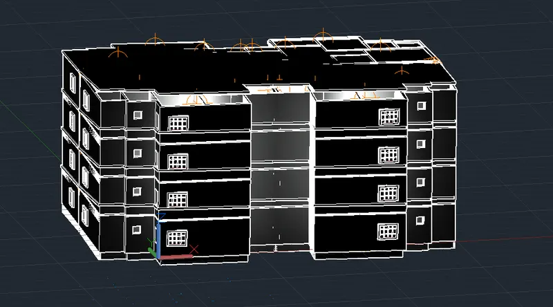
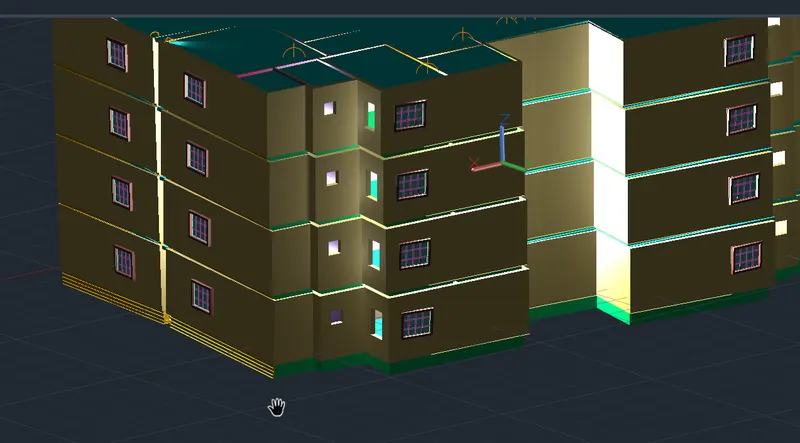
Project 2_Creating a 3D rendered model for a Residential Building in AutoCad
AIM: To create a 3D rendered model for a Residential building in AutoCAD
INTROUCTION:
The main objective of the project is to understand about to create a plan in 2D, then convert it into 3D using AUTOCAD 3 D, applying materials and rendering.
AutOCAD is primarliy used for generating 2D sketches.While it is possible to create 3D objects, AUTOCAD is built around a flat,sketch -based interface.There objects are cylinders,spheres and wedges and many more .But then user use 2D objects and modify them using the 3Dcommands accordingly .So AUTOCAD 3Dvobject in AUTOCAD.These objects and modify them using the 3D commands accordingly .So AUTOCAD 3D commnds like Extrude,sweep,Resolve, and union are used by the useres.
Also , the user must know the important of the viewport feature if they are working on 3D Models.The viewport command allows the user to split the drawing area into different windows to project multiple views of the model.These include the top,front,left/right views of the object.This feature works great for the user and helps them to observe the model from different aspects.some 2D and 3D tools which was used while working on this project is as follows;
2D tools:
Line: The line object is the most basic and common object in AutoCad drawings of any discipline.Each segment is a line object that can be edited separately ,assigning properties such as layer.line type and line weight.
Construction line : Construction lines are temporary line work entities that can be used as references when creating and positioning other objects or line work.construction lines are either circles or straight lines that extend to infinity in both directions
Polgon: Creates an equilateral closed polyline.We can specify the number of sides of the polygon and whether it is inscribed or circumscribed.
Rectangle: When using the RECTANGLE command,absolute or relative coordinate values are used to defined the size of the rectangle .Actual dimesion values are preferrd to create the length and width of the rectangle.Command used-REC
Circle : Created a circle Command used -CIRCLE or C.
Erase : The erase command is used to remove or delete objects from the drawing.The selected objects can also be removed with the help of the 'Delete' button on the keyboard. we can also delete faces ,vertices , and meshes in 3D with the help of Erase command.
Copy : copies objects a specified distance in a specified direction.With the COPYMODE system variable,you can control whether multiple copies are created automatically.
Trim : Trims objects to meet the edges of other objects.Command used : TR
Layers : Use layers to control the visibilty of objects and to assign properties such as colour and line type. Objects on a layer normally assume the properties of that layer. However ,you can override any layer property of an object ,For examples,if an object's colour property is set to BYLAYER,the object displays the colour of that layer.if an object's colour property is set to BYLAYER , the object displays the colour of that layer.if the object's colour is set to Red, the object displays as red, regradless of the colour assigned to that layer.command used- LAYER
Mirror : The mirror command in AUTOCAD is used to create a copy of the selected object.we can also delet the source object after mirroring the object.The objects that represent the same as the half of their object can be mirrored across a center line to create the other half of the object.
Offset: Creates concentric circles ,paralles lines, and parallel curves .command used: OFFSET
Extend: Extends object to meet the edges of the other objects.To Extend objects ,first select the boundaries. The press Enter and select the object that you want to exted .To
Array: Create coopies of objects arranged in a pattern.We can create copies of objects in a regularly spaced rectangular,polar,or path array.
Move: The move command in AUTOCAD is used to move objects at a specified distance and direction. To move the objects with precision,we can use objects snaps,grids snaps,coordinates,etc.
Rotate: Used to rotate objects in our drawing around a specified base point.To determine the angle of rotation,we can enter an angle value,drag using the cursor,or specifiy a reference angle to align to an absolute angle.command used: ROTATE
Dimesion:Create multiple dimension and types of dimension with a single command.We can select objects or points on objects to dimension, and then click to place the dimension line.When we hover over an object,the DIM command automatically generates apreview of a suitable dimension type to use.
Text: We can use single -line text to create one or more lines of text, where each text lines is an independent object that you can move , format,or otherwise modifiy. Right-click in the text box to select options on the shourtcut menu.
Fillet: The fillet tool helps form round corners between any two entities that form a sharp vertex.Command used : FILLETETC.
3D tools:
Revolve
Draw>modeling>Revolve
Extrude
Draw>modeling>Extrude
This AUTOCAD 3D Extrude command allows the user to create a 3D objects by extruding a 2D face along a line or path. for example ,A cylinder can be created by selecting a 2D circle and extruding it along with path.
Sweep
Draw >Modeling>sweep
This command helps the user to extrude the 2D objects without the 2D face being orthogonal to the begining of the path.
Union
Modify>Solids editing >union
This AUTOCAD 3D command allows the user to combine two objects converting them into one single object.
Substract
Modify >solids editting > subtract
This command is opposite to the union command ; this command works when there is a area in both the objects.Then this command substract the object A from the object.B
Intersect
Modify >solild Editing > Intersect
Wtith this AUTOCAD 3D command , the user is left with the area that is command to both the objects.
RENDERING
Rendering is the process of creating a raster image based on the 3D objects in a scene. A render is used to calculate the appearnce of the materials attached to lights placed in a scene .Environemental and exposure setting of the rendere can be adjusted to control the final rendered image.
APPLYING MATERIALS
- Click Visualize tab Materials panel Materials Browser.Find
- Select the objects which you want to assign the material.
- In the materials Browser,right-click the material to assign and choose Assign to selection.
- The material is assingned to the objects.
Applying a material using the tool palettes
- click view tab palettes panel Tool palettes.Find
- On the Tool palettes Window ,click a tab to set the tool palette current.
- Drag a material tool from the tool palette onto the object.
Applying a material by layer
Click visualize tab materials panel ( expanded) Attach by layer .Find list onto a layer in the layers list.
The materials is assigned to all objects on the layer whose material property is set to Bylayer.
To remove applied materials
- Click visualize tab Materials panel (expanded) Remove Materials.
- Select an Object Whose materials you want to remove. The material removed from the objects and replaced by the Bylayer material. Etc.
OBJECTIVE:
The main objective of this project is to review and refresh almost most of the tools which will be used by a proffessional engineer while drafting a 3D drawing .This will strat from the intial drafting in 2D using lines and rectangles to rendering in 3D.The entire project can be completed in 14 steps and are as follows.
- To draw the plans using AutoCAD 2 D
- To project walls to convert the plan from AUTOCAD 2d to autocad3d
- To design the staircase
- Designing and placing of 3D doors, swinging louver ,sliding window ,normal window ,normal window and glass grill.
- Adding lights and colouring of walls
- Adding chajja and 3D mirroring of the flat.
- Adding lift and roof.
- Designing and placement of staircase rails.
- Adding mumty ,parapet wall and copoying floors
- Rendering .
PROCEDURE:
Step 1: To draw the plan using AutoAD 2D.
Type UN and press enter
under Drawing units , Select Architectural (feet and inches)
Now the lower limit is set 0',0' and upper limit to 100',100'
Type z enter to zoom and A enter to all.
Default layer for materials like walls,windows,grills,steps and stairs, dimensions and text was made and was assigned with a colour.
Using the line,rectangle,constrution lines the plan layout of a single residential building was prepared as shown
Doors and Windows was provided at places necessary as shown in plan.
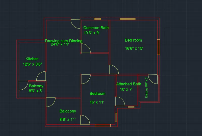
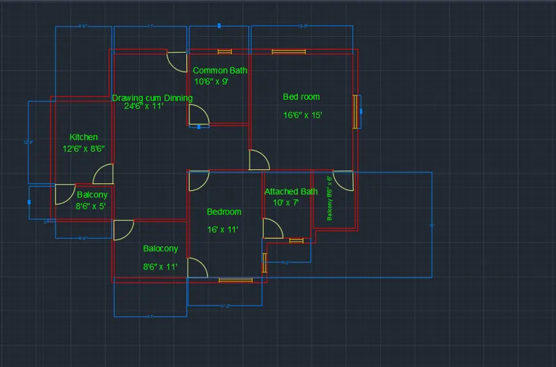
By providing a suitable style all the required texts was also made using the DIMLIM command the dimensioning was completed.
The staircase and steps , Common corridor was made next.
Using the mirror command , the plan prepared was mirrored to obtain the ground floor of residential flat s shown.
The residential flat has the same plan throughou 4 floors. As plan layout is same throughout the entire designing will be carried out in the single residential building than the entire floor.
In order to do that a copy of the single residential flat was made and all the works was carried on it.
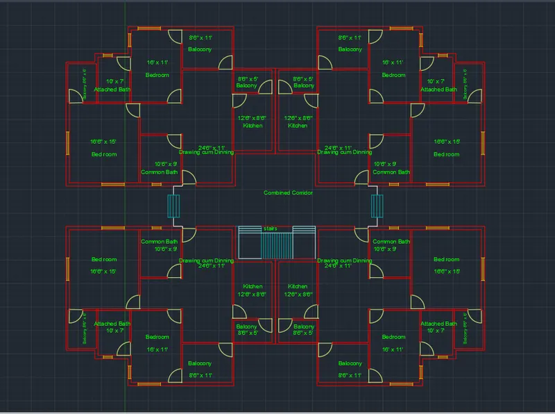
STEP 2: To project walls to convert the plan from AUtoCAD 2D to AutoCAD 3D .
Now in settings select 3D modelling and visual style control to 2D wireframe to move to AutoCAD 3D.
A copy of the residential flat was made to work with. View use is south westisometric view.
Turn off all layers except the wall layer.
Select the entire drawing and type J to join the entire drawing.Now click on EXtrude command in the home tab and press enter move mouse in upward direction and speciy height 9'6" and press enter.Now the 3D wall is formed.
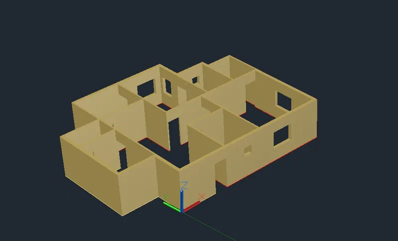
Door Cut-outs:
Using the REC comman draw a rectangle connecting the top of all door openings. After drawing all the rectangles select the extrude command in the home tab and press enter , move mousd in downward direction and spefcify heigth as 2'6" and press enter.Now the door cut-outs of 7' is formed.
Also it means that the lintel beam will be at a height of 7' from the plinth level.
Now using the union option in solid editing panel select the complete drawing to union all the elements in the drwing.
Window cut-outs
Now turn off the wall layer and turn on the window layer. Using the REC command rectangle was drawn across all the window portion at the plinth level.Select all the rectangle just formed and move recrtangle upward by 7'
All the main windows was extruded by 4' and the small toilet window was extruded by 2' downward.
Using the subtract option in solid editing panel the window rectangle panel the window rectangle was subtracted from the wall and thus the window cut-outs was made.
Trun off the window layer and trun on the grill layer.
In the same way window was made rectangle was srawn at plinth level at the grills in the balcony.
They are then moved upward by 2'6" .Select all rectangles and extrude them by 6' in upward direction.
Using the subtraction option in solid editing panel the grill cuboid was substracted from the wall and thus the balcony portion was made.
Floor Level:
using the polyline draw lines connecting the outer wall of the building at the top.
Now using the move command,move the polyline made downwards to the plinth level. Using the extrude command extrude the polyline by 2' hence forming the floor.
Command corridor and plinth From the 2D plan created, using the polyline draw lines connecting corridor and lifit room.
Then with copy command copy the polyline and place it in 3D plan using the endpoints selected.
Now extrude the polyline downwards by 2' to obtain the command corridor.
Also draw polylines at the plinth level throughout and using offset command offset it outward by 6"
Join all the polylines just created using the joints command and then extrude the polyline by 2' upwards to create the plinth.
Step 3: To design the staircase
STAIR CASE
In the layer panel turn on the staircase layer. Now using the press pull option in home tab press pull each step by 6" (6",12" , 18"etc) that is in every successive step the extrusion height will be increased by 6
Using the union option in solid editing panel union all the steps to become a single unit.
Using the press pull command in the solid editing panel press pull the bottom portion of staircase by drawing a line using the line command as required.It has to be done 3 times to remove all the below portions and to complete the loop.
Using the move command the staircase was selected and moved to the extact postion in the 3D drawing using the endpoints.
STEPS:
Turn off stair case layer and turn on the steps layer.Rectangle was made first as per the 2d dimension and then the 3D steps was extruded by height of 6",12" and 18".
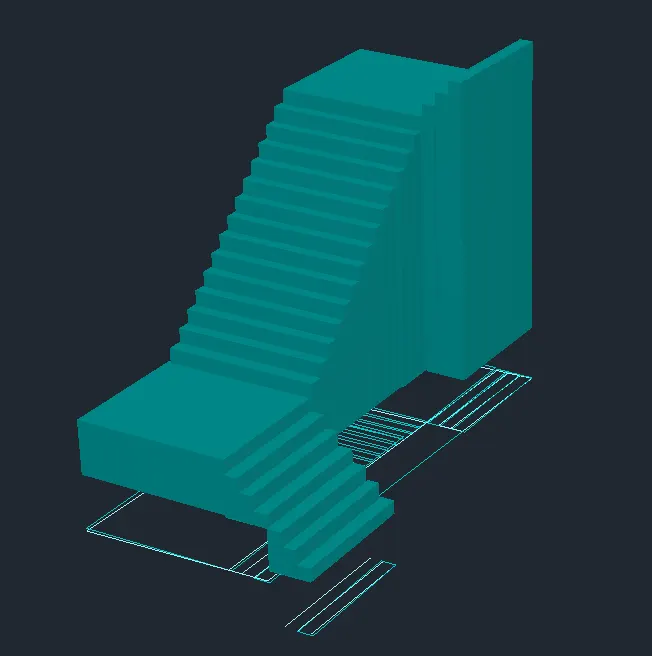
Use union command to join the steps.
Using the move command he steps was selected and moved to the extact position in the 3D drawing using the end points.
Now with 3D mirror command mirror the steps with respect to a plane parallel to YZ plane that is we have to specify the planes by clicking on 3points and step will be formed it at the other end of the corridor.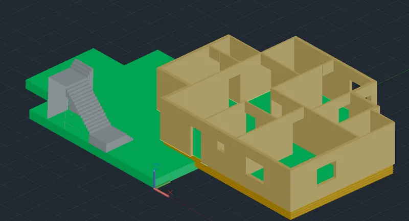
STEP 4: Designing and placing of 3D doors ,swinging louver,sliding window, normal window and glass grill.
The 3D doors, swinging louver,sliding window,normal window and glass grill was designed using the tools polyline,sweep,extrude,union,3D rotate, subtract command etc.
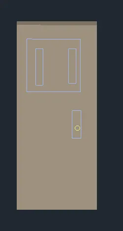
Applying materials:
On the visualize tab click on materials for 3D door ,swinging louver,sliding window,normal window and glass grill as shown.
We can apply materials by just dragging the materials from the library to the object which is to be materialized.
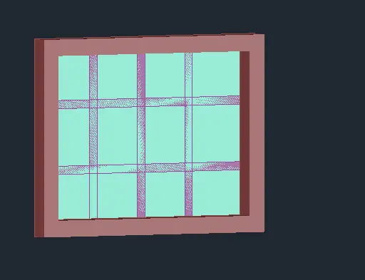
All of the materials was copied upto the number of times it was required, using the 3D rotate command it was rotated to the required direction and then they all are placed at their respective positions at shown.
STEP 5:Adding lights and colouring of walls wall colouring:
Click on colour face tool in the solid editing panel to apply colours to each room faces as shown.Select the faces carefully and after selecting faces press enter and select the colour of our choice and click ok.
Keep repeating this process until complection. Using the materials library in visualization tab the flooring was also applied.
Also the plinth level was also assigned to stone materials. In the similar manner the corridor,steps and staircase was lso applied with materials.
Adding lights:
In order to apply lights a diagonal line was draw in each room using the line command.
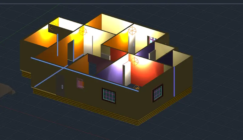
In visualization tab select the create light option,turn off the default lighting and then place the light at the center of diagona,click on intensity factor click on 20 and click enter twice.
Repat this process and do it for other rooms as well.
Now select all the diagonal lines created and deleted them.
Select all the lights created and move them downwards by 2'.
STEP-6 Adding chajja and 3D mirroring of the flat.
The chajja/sunshades was made next using the polyline and have to make sure to turn on the dynamic UCS.
The sunshades was made by extruding the lines drawing using polylines by 18'
MIRRORING OF THE FLAT:
Now with 3Dmirror command mirror the FLAT with respect to a plane parallel to YZ plane that is we have to specify the planes by clicking on 3 points and the flat will be formed it at the other end.
Now using the union command join the two plinth.
Repeat the union command join the two plinth.
Repeat the union command and join the walls as well.
The two flat are to be mirrored again to finish the floor.Now with 3Dmirror command mirror the FLAT with respect to a plane parallel to YZ plane that is we have to specify the planes by clicking on 3points and the flat will be formed it at the other end.
Thus the four flats are now created as shown. The staircase portion was not selected while mirroring as I decided to provide a lift room there
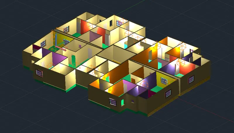
STEP 8: Adding lift room and roof LIFTROOM:
Lift was made next using the rectangle ,extrusion,union,slice and materials was applied from the materials was applied from the materials browser in the visualization tab.
Lighting was also applied as done above.
ROOFING
In 2D wireframe draw a polyline the plinth. Using the move command move it upwards by 9'6"
Using the eextrude tool extrude it upwards by 6".
Staircase and lift projection Upwards: Now draw a rectangle along the outer boundary of staircase room and lift room. Select the rectangle and extrude it upwards by any height. Using the substract tool substract the lift room and staircase room from the roof to ake space for them.
STEP7: Desinging and placement of staircase rails
The railling of staircase was drawn next. Copy the stair from the building to outside so that we can work on it. Click on cylinder in the modify panel and create a cyclinder of radius 1" and height as 2'6". Copy this cylinder and place it on each steps as shown.
Using thepolyline draw a line such that it connects all the cylinders just made at the center and at the top portion.
A circle of radius .5" was drawn . Using the sweep tool , the circle was selected and appliyed it to the polyline created.
Now using the copy tool copy the polyline by 6",12" and 18" and place it 3 times at the distances mentioned.
Now materials was applied from the materials library in visualization tab .
The handrail and steps was assigned with materials of our choice.
The handrails was then moved and placed in the correct position as shown.
STEP 9: Adding mumty ,parapet wall and copying floors
In the 2D wireframe visualization with front view select the complete building , deselect the lifits from top to bottom till at a distance of 10' in upward direction.
Now isolate the roof of the 1st floor After that guard wall was built on both sides of corridor in the 1st floor using polyline,extrude and truning on dynamics UCS
Now unhide the roof as shown.
select the roof and copy it to a height of about 20' from 1st floor. Select the complete first floor now and copy it and place at 10' and 20' from top.
After that the mumty was created at the top using the rectangle, offset,extrude , subtract and move commands. The door cut -out was made and a door was placed at the top
Now using a polylie a line was drawn across the roof completely and offset it by 6" to the inwards and again by 3"
STEP :-9 Rendering
Rendering at edge's eye was done here.
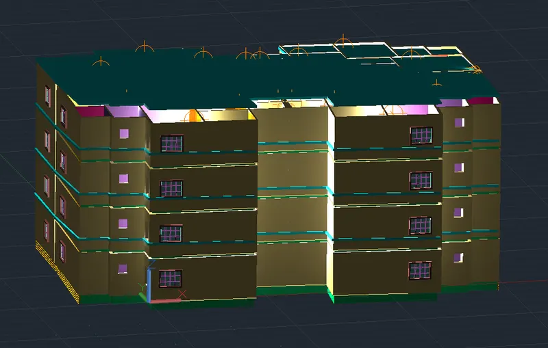
The camera was placed at necessary places around the whole buildinh at some height.
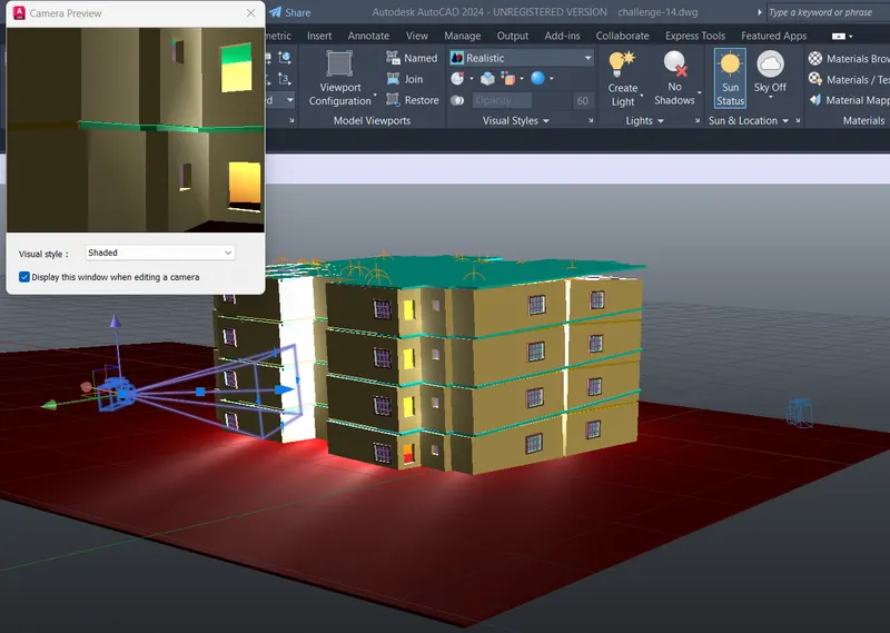
Grass site work was applied at floor from material library in visualization tab.
RESULTS:-