Creating Conceptual mass in REVIT and Creation of Sinusoidal curve and a Parametric stadium using Dynamo
1) Using Dynamo create a set of sinusoidal points and create a curve and create a surface out of the curve.
Ans) AIM:- To create a set sinusoidal points, a curve and a surface out of the curve using dynamo.
PROCEDURE:
- Intially , open the architecture template of revit software and go to manage tab.
- In manage tab select the dynamo.
- Then dynamo window opens and then go to new option.
- Now, start the process by intserting three integer slider.
- This can be done by typing code block in the library search panel.
- One block is named start (value -5),
- Second one end (Value -300).
- Thrid one step(Value -1)
- Now, type range in the search panel of the library and insert it.
- Now,connect these three code block as input to the range block.
- Now, search points by coordinates in the search panel.
- Then, connect the range block to the X coordinate of the point by coordinate block.
- Now, we have to produce sin wave out of these points for which we have to insert sin function which given by math.sin option in the library.
- Sin values are very small so, we need to amplify it . For this, insert another integer slider and name it as amplifier.
- This, amplifier code block needs to be multiplied to the sin block.
- For this, search product function in the library.
- Input for x values is sin block for Y value is amplifier.
- Next, we have to provide phase for the sin curve.
- So, again insert an integer slider and name it as phase.
- Now,the phase block is then added to the amplified sin block
- For this insert add operater block from library.
- Now, this is then connected to they coordinate of the points by coordinates block.
- Hence , the set of sinusoidal points are obtained.
- Now, we have to convert them to a curve.
- The curve can be created from nurbscurve.
- Search nurbscurve in library and choose nurbs curve by control points
- Now, connect the points by coordinate block as input for the nurbs curve. A line will be developed connecting the points.
- Hence, sinusoidal curve is also developed.
- The next step is to develop surface.
- For this, first created a group by selecting the required input blocks and then go to edit option in the top portion and then choose created node from selection.
- The entire thing will be grouped together.
- Now,copy this entire blocks two times to create the surface.
- Adjust phase to view the two curves that is copied.
- Next step is to create the surface.
- For this , first create a list.
- This can be done by searching list. create in the search panel of library.
- Then connection all the output of the sine curves as input for the list.
- This will serve as the input for surface by loft block.
- Now, we have to create the surface.
- For this , search surface by loft.
- Hence, the surface is developed out of the curve.
RESULT:-
- A set of sinusoidal points have been created as follows:
2.
AIM:- To create a conceptual layout of a floor plan in dynamo.
PROCEDURE:-
- Open a new architectural template.
- Go to mange tab and open the dynamo----> New.
- Inorder to create the wall first we have to create four control points.
- For this, search points by coordinates in the search panel of the library.
- 1st one is named as origin (0,0,0) and the rest is named as control point 1(x,0,0) , control poinnt 2(0,y,0) and control point 3(x,y,0).
- Now, provide two integer sliders to provide the values for x and y.
- Now, we have to connect these points by a line.
- So for this , search line by start and end point and insert 4 blocks.
- The input for these blocks are the points created previously.
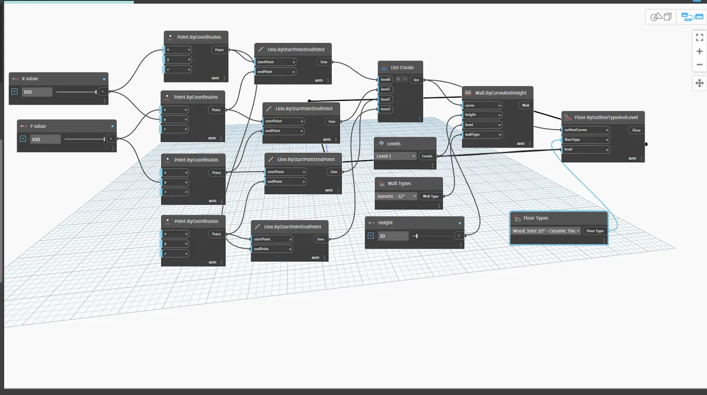
- Hence, the layout of the floor plan is obtained.
- Now, search wall in the panel and choose wall by curve and height.
- So, for this input required are curve , height , level and wall type . Inputs are given as follows.
- For curve , combine all the four lines in a list by choosing list. create.
- For level, search level in the search panel it will contain the levels avaliable in your revit folder. Then chooose the level in which you want to place your structure.
- For wall type,search wall type in the panel and it will dispaly the wall types linked in the revit file.
- The floor plan layout is given below:
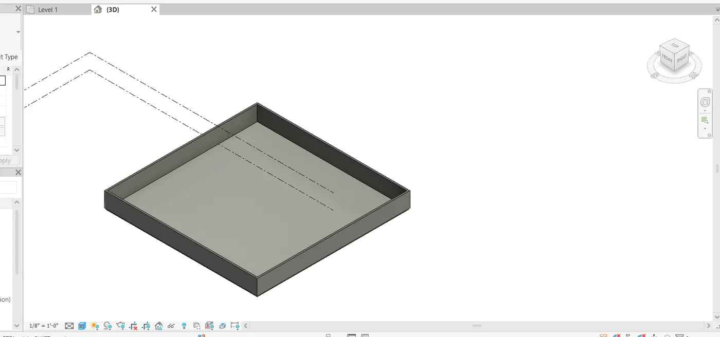
- Now, go to revit file to view the 3D from where the height of the wall is visible.
- The height of the wall can be adjusted using the slider.
- Now, we have to place the floor.
- For this , type floor in the library and select floor by outline curve, floor type and level.
- This can be viewd in 3D in revit file.
Result:
Hence the conceptual floor plan layout has been developed and is as follows:
3.
AIM:- To create an array of model elements in revit.
PROCEDURE:-
- Open a new architecural template in revit file.
- In that go to architecture tab------> columns----> Architectural column---> place the column(610mmx 610mm)
- Now, similarly 16 columns are created.
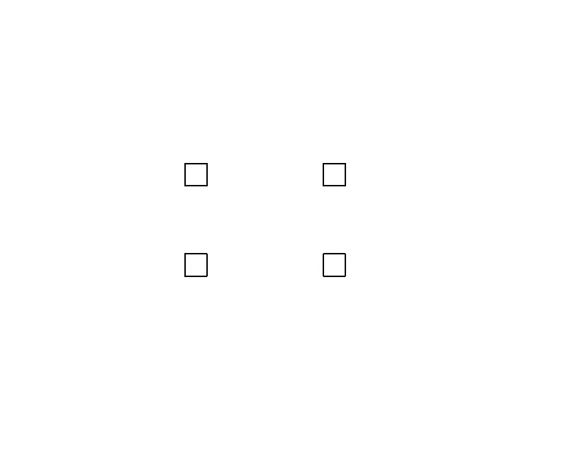
- The properties of the model elements are varied using dynamo.
- Now, open dynamo.
- In the search panel of the library search model elements , integer slider and set rotation.
- The integer slider is renamed as rotation angle.
- Now, select model elements block will be input for family instance and integer slider ( rotation angle) will be the input for family instance and integer slider ( rotation angle) will be input for degree.
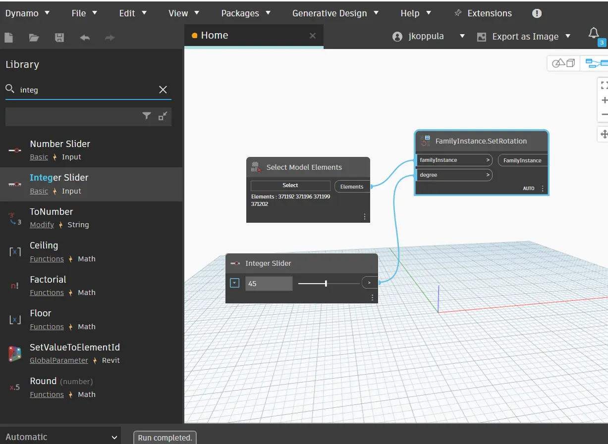
- The rotation angle ccan be varied to desired value.
Result:
The array of model elements have been creted and their properties are being varied through the blocks created in dynamo.
4.
AIM:- To create a conceptual mass in Revit and develop a parametric column by dividing the surfaces.
Procedure:
- Open revit software and under the families open a new ---> conceptual mass---->mass.
- Now, go to elevation view and created a level at 3.6m and name it as Height of roof.
- Now, using spline tool draw the desired outline for the walkway.
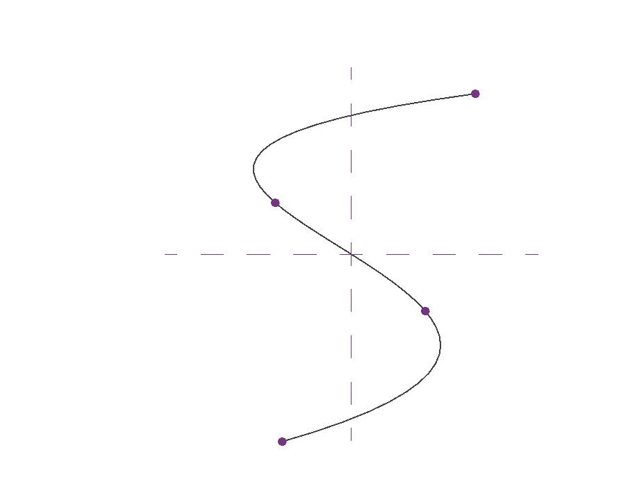
- Now, we have to create a profile to sweep through the curve.
- For this,we have to set workplane keeping the point as centre.
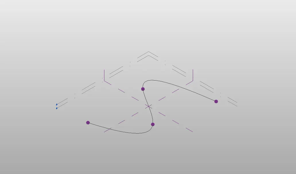
- Now, a polygon is developed with point as center.
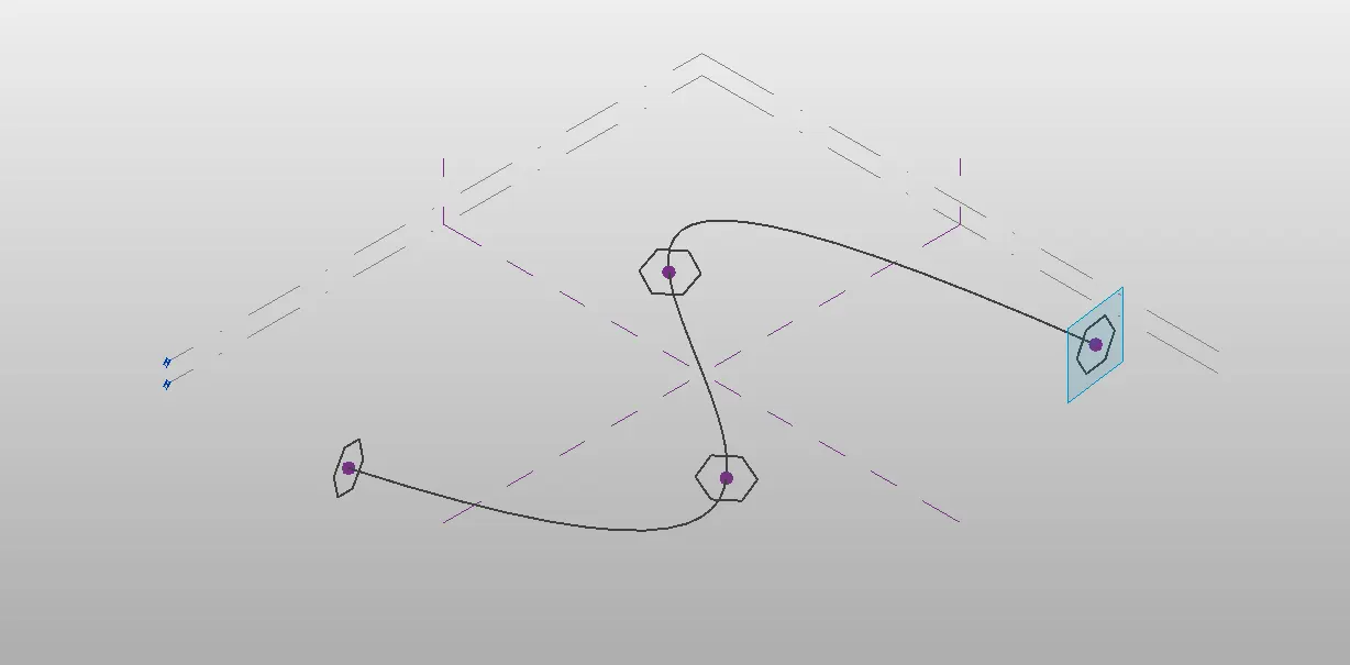
- similarly , workplane and polygon is developed at all nodes.
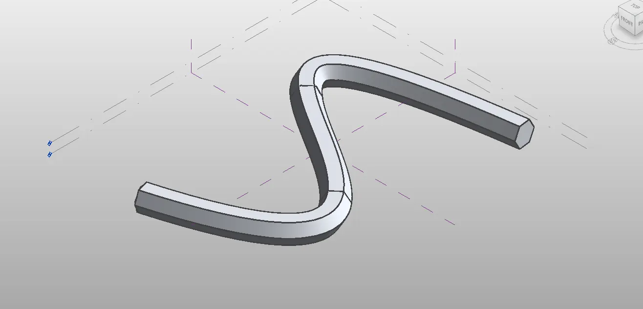
- Now, we have to create the surface which done through sweep.
- For this, select all the polygons and the curve line and choose create from option.
- Now, select the entire form and then filter and retain only the form.
- Now, select the form ----> divide surface ---> Then provide the pattern (triangle bent).
- Now, Open a new family ---> curtain panel based.
- Now, select the pattern as triangle bent.
- Then, create a reference point at center of the face.
- Then draw a circle of radius 3" at that reference point.
- Now, select the pattern, reference plane and circle created and choose create form.
- Now,load this into the project.
- Now, select the entire form of the walkway and filter it to retain only the divided surface.
- Then in the pattern select the family that we have created just now.
Hence, the conceptual mass have been created.
Result:
The conceptual mass have been created in Revit and is given as follows:
5.
AIM:
To develop a parametric stadium using dynamo in Revit.
Procedure:
- Intially open a new architectural template in Revit and then open dynamo.
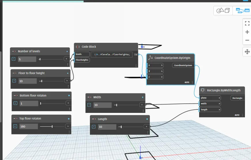
- Basic parameters to design a high rise structure is created as input in dynamo.
- Four integer sliders is taken from the libraray for the following:
- Number of levels
- Floor to floor height
- Bottom floor rotaion
- Top floor rotation
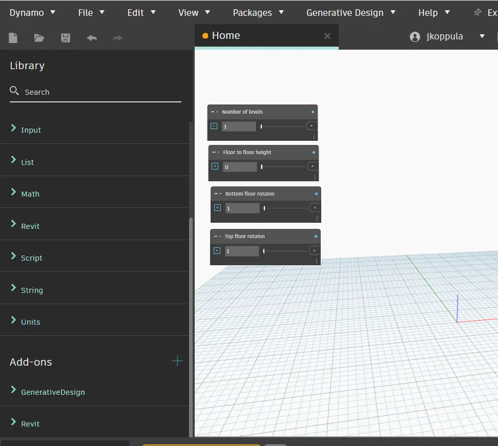
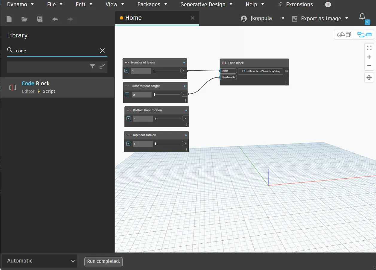
- Now, insert a code block from the library to combine level and floor to floor height and type 0 . . # levels ..Floorheight.
- Now, connect the integer sliders named as levels and floor height as input to the code block.
- Now, search coordinates by origin in the library and insert it.
- Then connect the code block as input for z coordinate in the coordinate by orgin block.
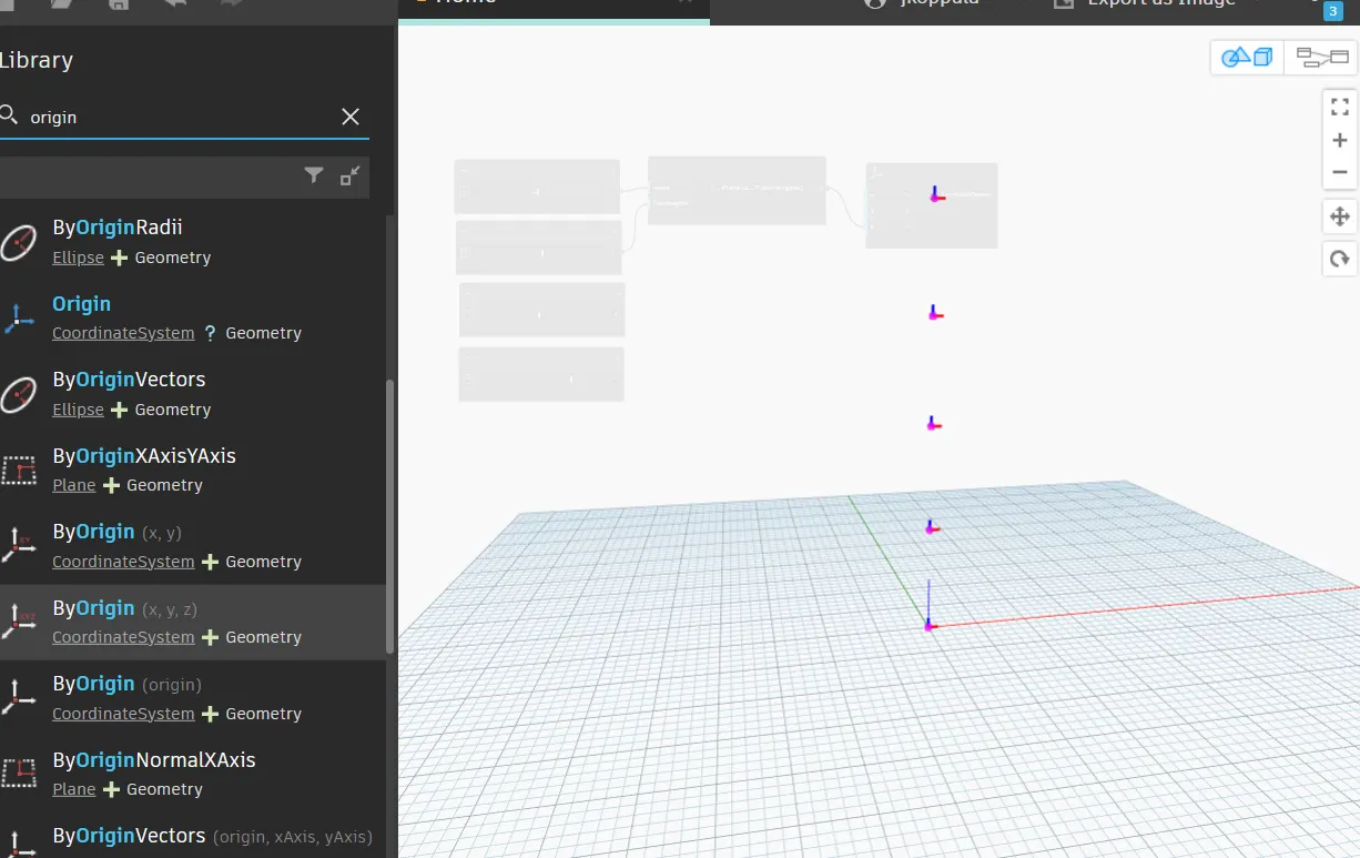
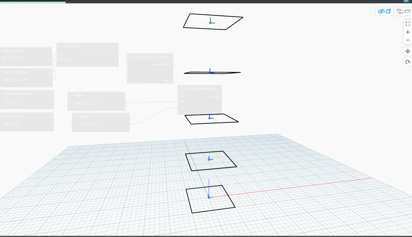
- Five points are generated correspoinding to 5 leves.
- Now, insert rectangle by width and length from the library.
- For this, input required are coordinates system , length and width.
- So insert integer slider for length and width.
- Then connect the inputs for the rectangle block.
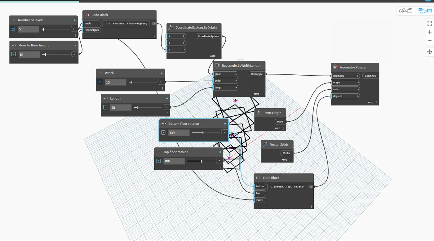
- Now we have to rotate the gemometry.
- so,for this insert the rotate block from the library . The inputs reqiured are:
- Geomerty : Rectangle block
- Origin insert an orign block from the library.
- Axis : insert vector Z axis from the library.
- Degrees: For this insert a code block and type Bottom floor rotation , top floor rotaion and levels.
- Now, we have to create surface , for this surface by loft in library.
- Then connect Geometry rotate block as input for surfae by loft.
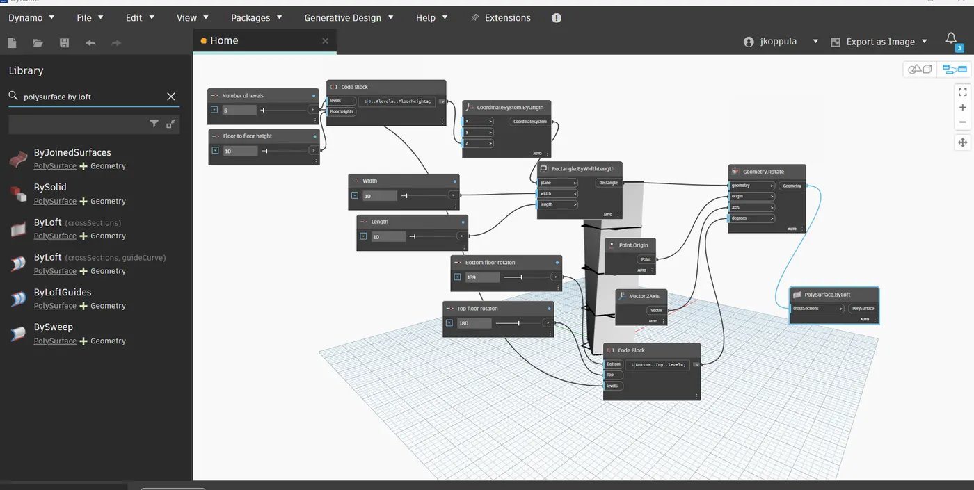
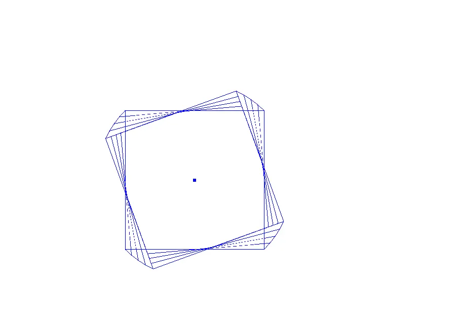
- Hence, the parametric stadium have been created.
- The number of leves and width and length of the rectangle can varied accordingly.
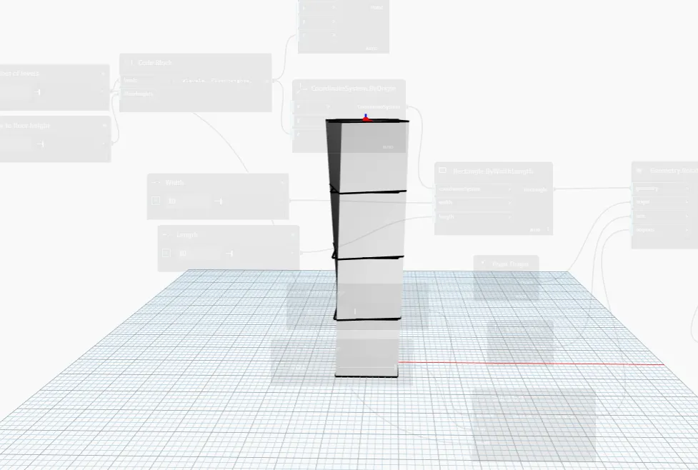
- In revit structure is visible as follows:
Result:
The parametric Stadium have been created and is as given below: