Project 2
1. Design a Warehouse Building located in Chennai using STAAD Pro Connect Edition. The specification must be as follows:
|
Width |
30m |
|
Length |
50m |
|
Eave Height |
9m |
|
Bay spacing |
6m |
|
Soil type |
Medium |
|
Safe Bearing Capacity |
200 kN/m2 |
|
Roof slope |
1 in 12 |
Assume suitable sections for structural elements. Follow IS800:2007, IS1893 and IS 875
- Prepare a Design Basis Report for the project
- Create structural model using STAAD Pro Connect Edition
- Prepare DL, LL, WL and EQL load calculations as per IS 875 standards
- Design using MS – Excel
- Steel column
- Rafter
- Base plate
- Pedestal
- Z- purlin
A)
AIM: Design a warehouse Building located in chennai using STAAD Pro Connect Edition
- Prepare a Design Basis Report for the project
- Create structural model using STAAD Pro Connection Edition
- Prepare DL,LL,WL and EQL Load calculations as per as IS 875 standards
- Design using MS -Excel
- Steel Column
- Rafter
- Base plate
- Pedestal
- Z-purlin
- Design Foundation using STAAD Foundation.
- Attach necessary sketches and drawings wherever required.
- All stipulations, assumptions and design parameter must adhere to indian standards.
INTRODUCTION:
To create a model by using data and apply loads dead load live loads and wind loads
- Section 7 IS 800:2007
- BUckling class
- Effective length column
- Cross sectional shapes (Built up columns).
Web bucking:
- Web buckling occurs when intensity of compressive stress near the center of the section exceeds the critical buckling stress of web acting as a strut.
- at supports and under a concentrated load certian portion of the beam acts as a column to transfer the load.
- under this compressive force the web of the beam section may buckle.
Limit state of strength:
- Limit state strength are those associated with failures under the action of probable and most unfavorable load combinations on the structure using partial safety factor.
- The might endanger the safety of life and property.
- Checked by utilization ratio.
Limit state of serviceability:
- Limit state of serviceability are those associated with deformation and deflections which may adversely affective use of the structure.
- Checked by deflection limits.
PROCEDURE:
ROOF SLOPE CALCULATION:
Roof slope = 1in12
Width, b = 30m
X/(b/2) = 1/2
x = (30/2)/12 = 15/12
X = 1.25m
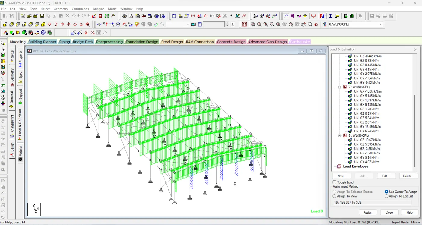
GEOMETRY/ MODEL CREATOR:
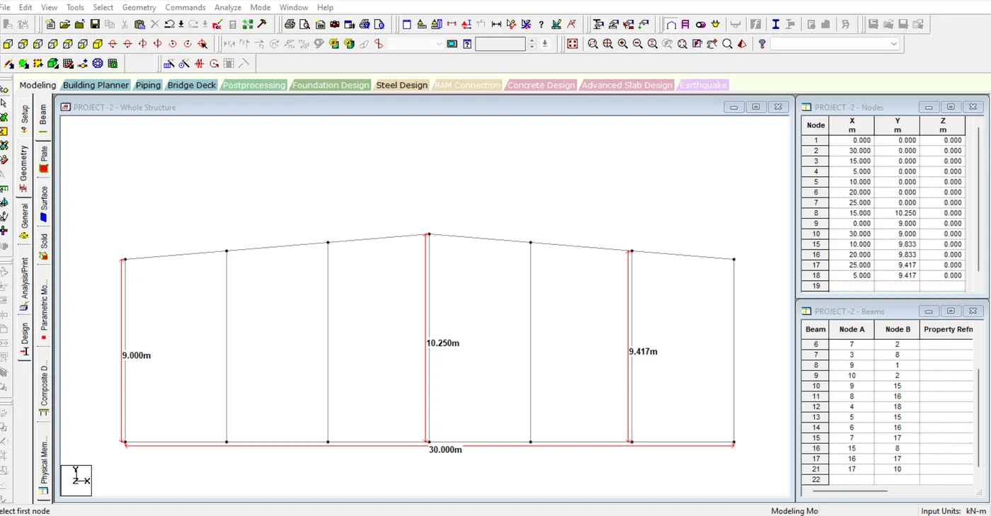
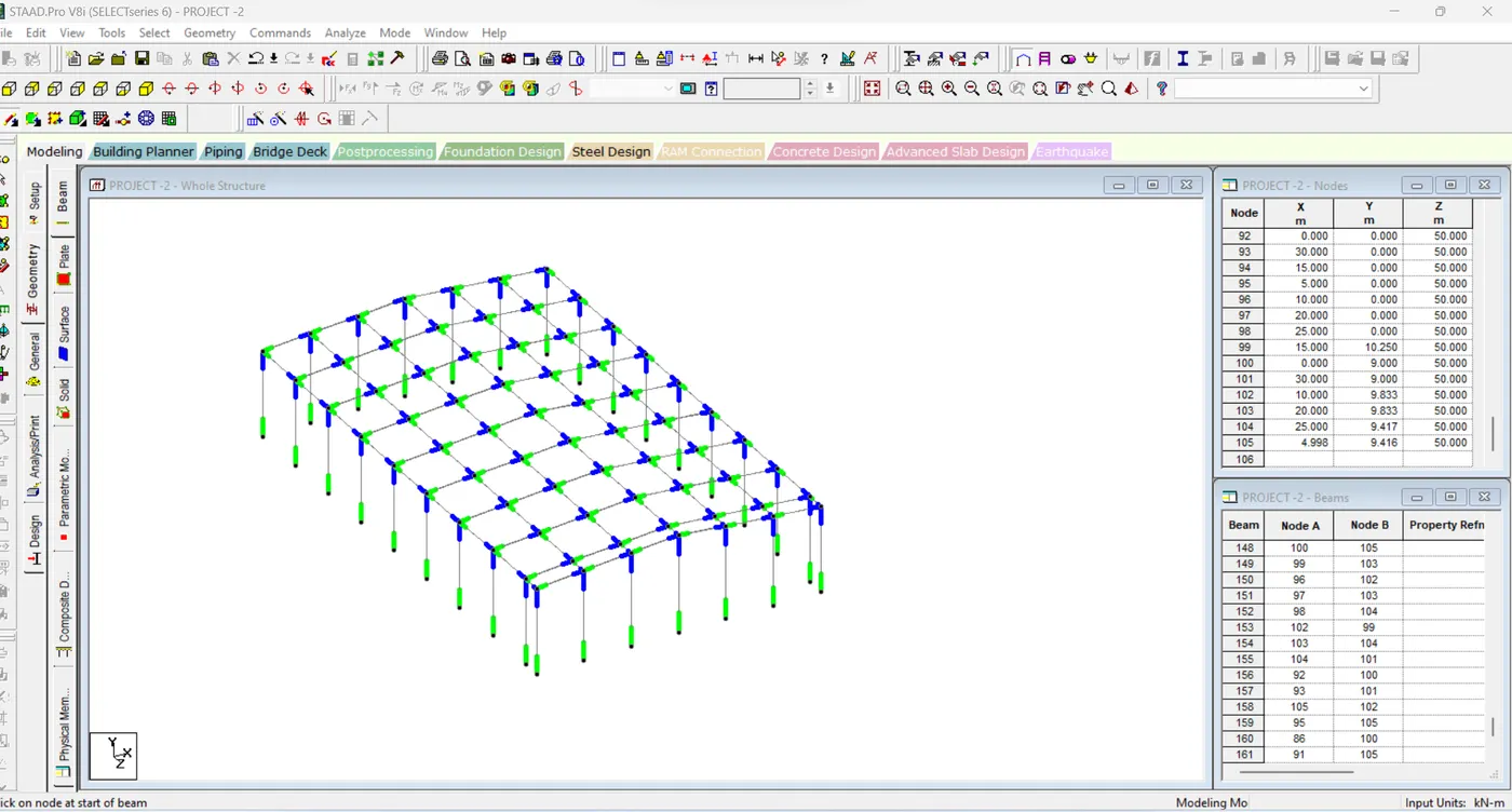
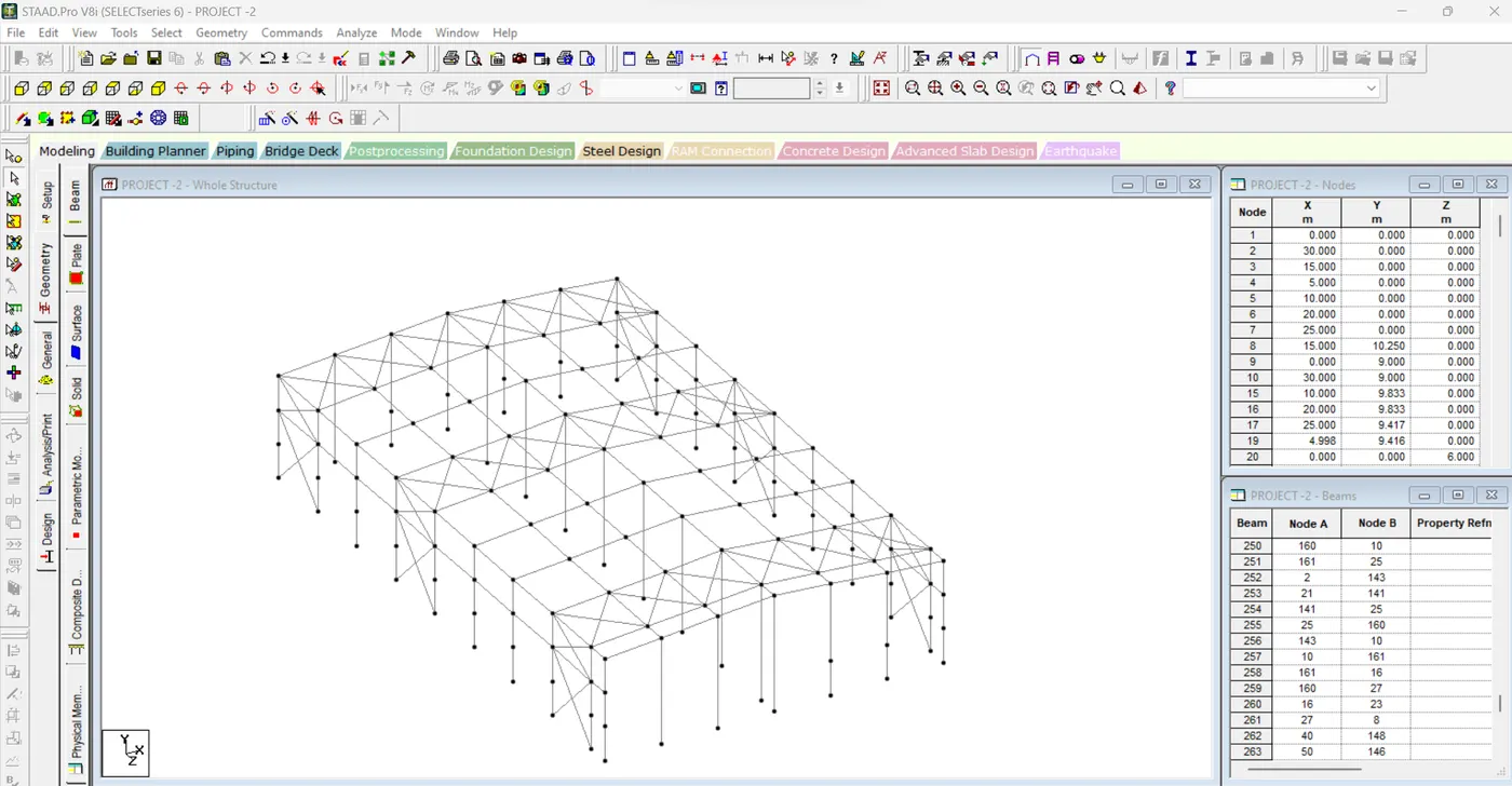
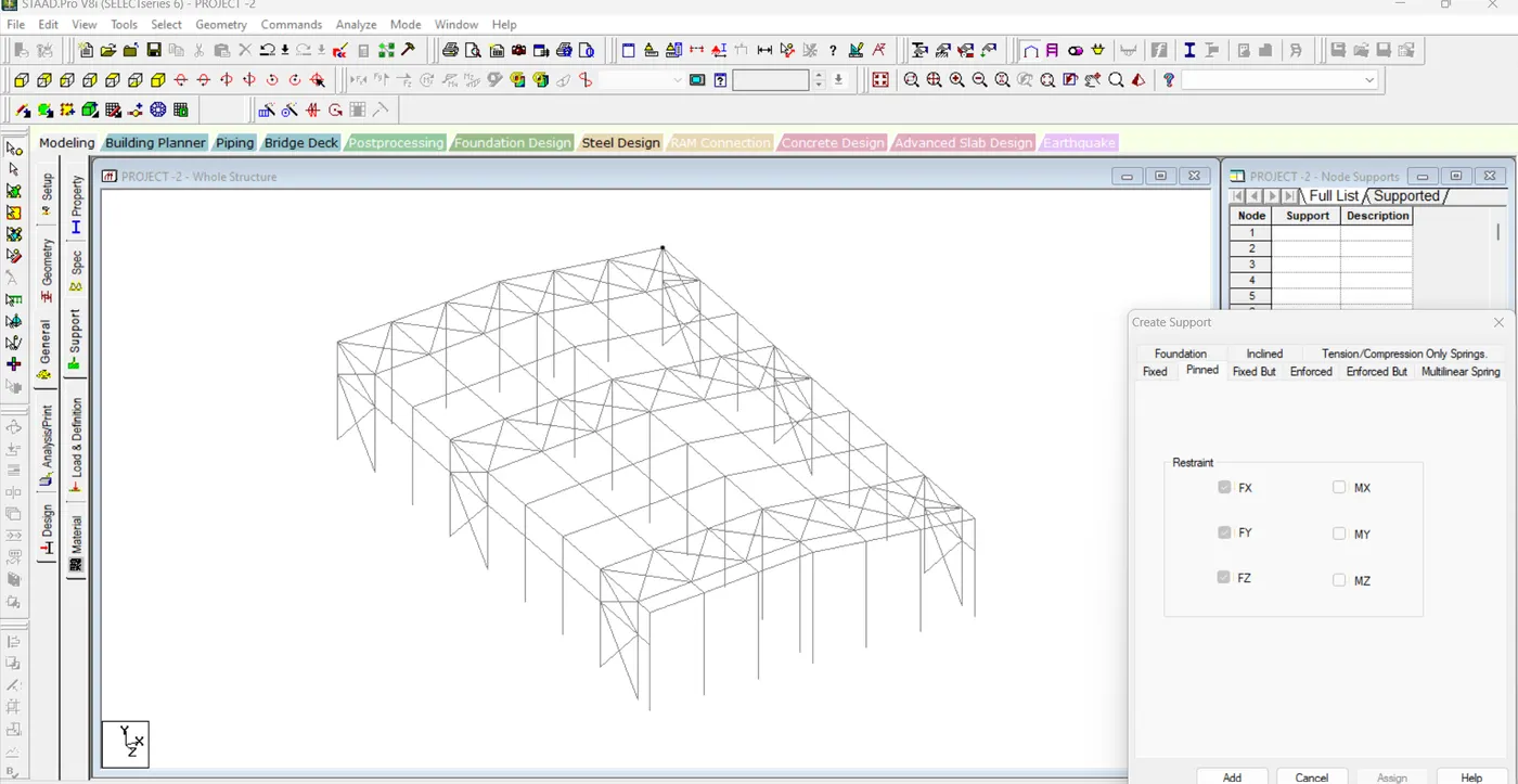
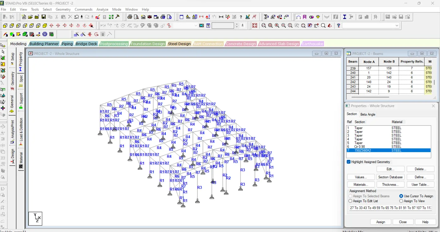
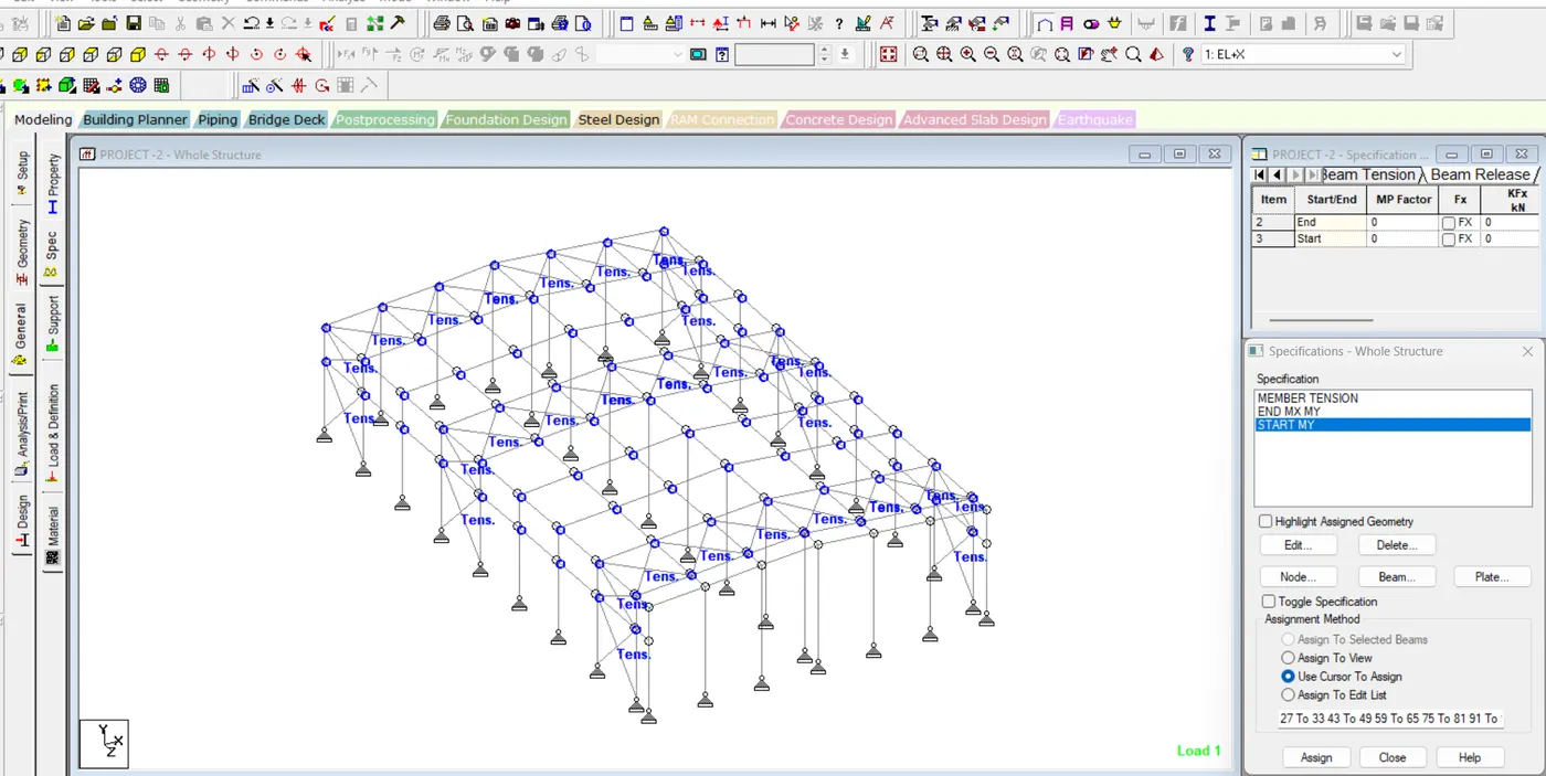
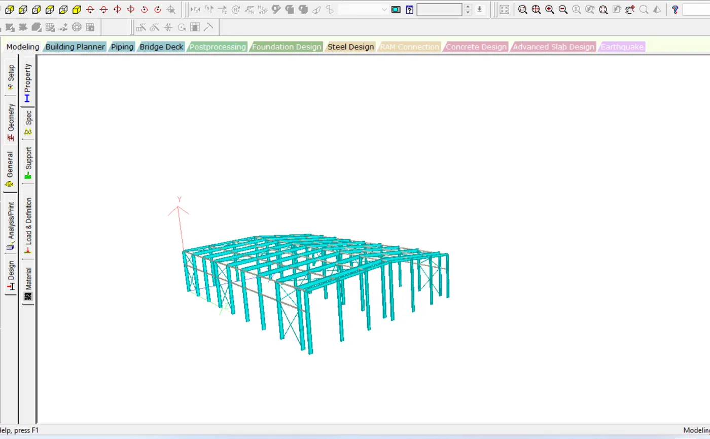
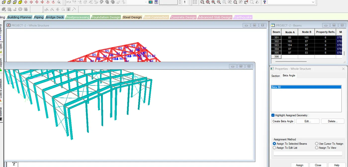
DEAD LOAD:
LIVE LOAD:
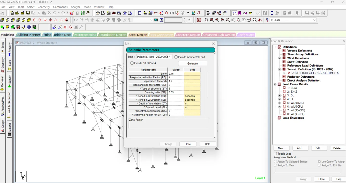
SEISIMIC LOAD:
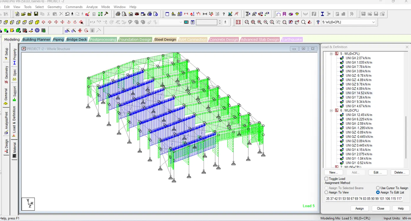
WIND LOAD W(0+CPi):
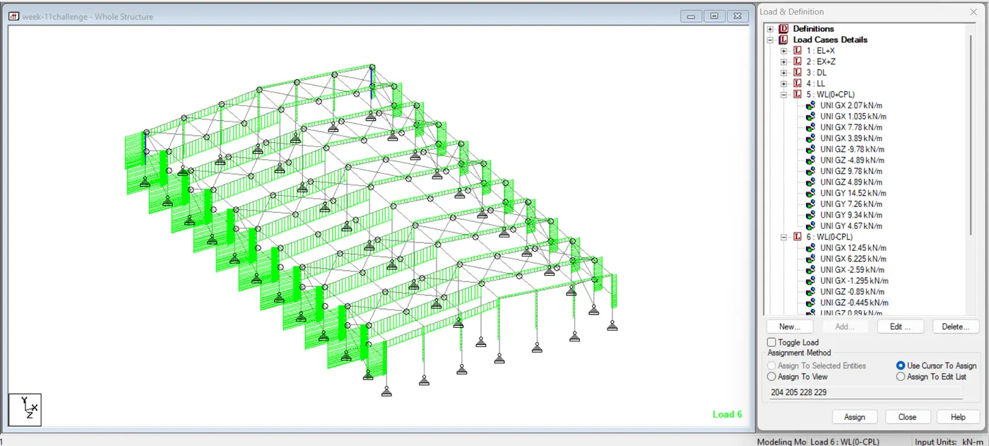
W(0-CPi):
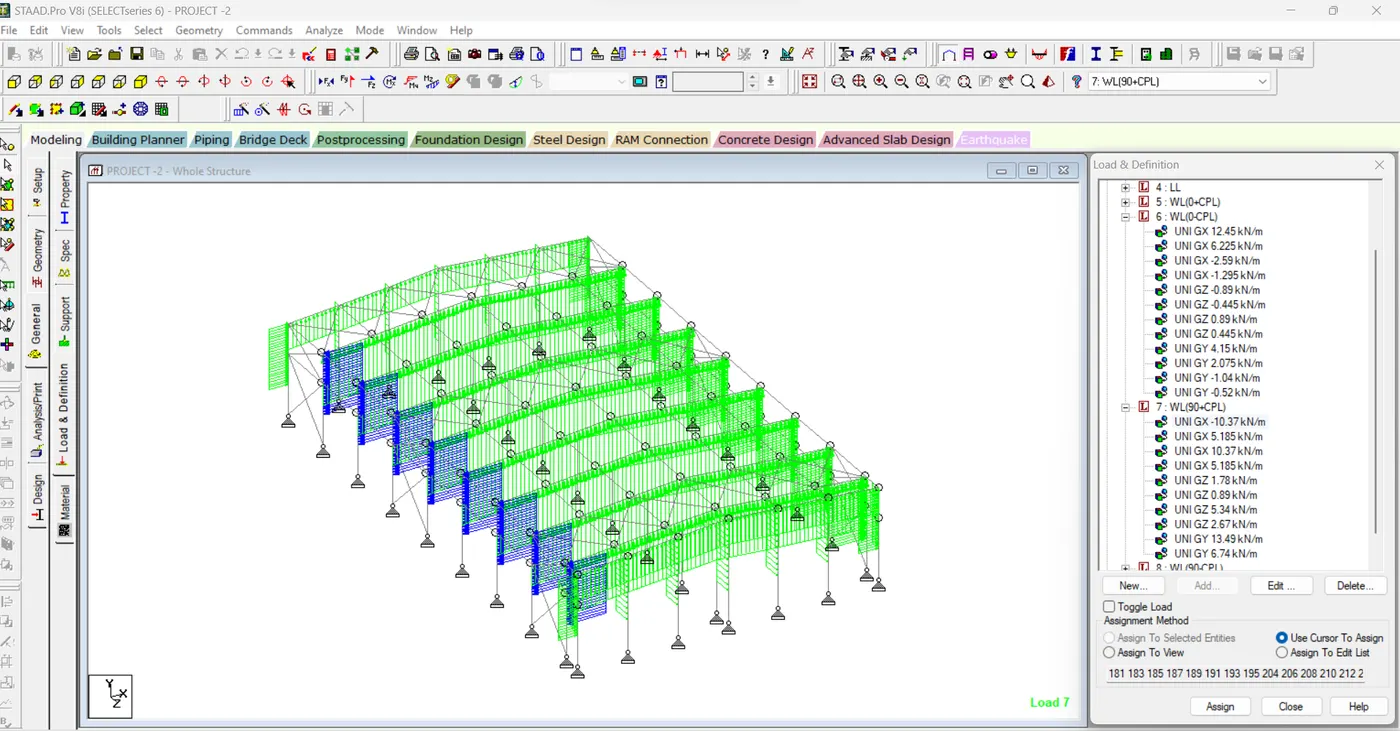
W(90+CPi):
W(90-CPi):
DESIGN OF STEEL COLUMN:
Solution:
Flange thickness t = 12.7mm
overall height of column ISMB400 = h = 400mm.
clear depth between flanges = d = 400 - (12.7 x 2)
=374.64mm
Thickneess of web = t = 10.6mm.
Flange width =2b = bf =250mm.
Hence half flange width = b =125mm.
slef- weight = w = 0.822 KN/m.
Area of cross- section =A = 10466mm2.
Radius of gyration about x = rx = 166.1mm.
Radius of gyratio anout Y = ry =51.6mm.
Step - 1
Types of section:
Properties of selected section
ISHB 400.
Flange criterion b/T = 125/12.7 = 9.8 <10.5
Web criterion d/t = 374.6/10.6 = 35.3<42
(Table 3.1 of IS : 800)
Hence,cross - section can be classified as "COMPACT".
step-2
Effective Length:
As, both ends are pin- jointed
Effective length ,KLx = 9m
KLy=9m
KLz=9m
Slenderness rations:
KLx/rx = 9000/166,1 =54.1
KLy/ry = 9000/51.6 = 174.41
Non-dimensional Effective slenderness ration
λ">λ =1.96
Step -3
To calculate :
h/bf = 1.60 >1.21
T=12.7mm
so buckling class = b = 0.34
φ = 0.5(1+(λ-0.2)+λ^2)
=2.76
Step - 4
Calculation of x from equation x :
= 0.214n/mm^2
Step - 5
Calculation of fcd:
fcd = Xfy/γm
=49.15
Step - 6
Factored axial load :
pd = Afcd
= 514.61 KN
DESIGN OF RAFTER :
Solution :
Span of Rafter = 6m
Dead load = 18KN/m
Imposed load = 40KN/m
support bearing = 100
yield strenght =250N/mm2
Step - 1
Design load calculation :
Factores load 1.5(DL+LL) = 87KN/m
Factored Bending moment = 391.5 KN/m
Step - 2
Section modulus Required:
Z req =1722600mm^3
= 1722.60cm^3
Step -3
Section classification :
Flange criterion B/2T =5
Web criterion (D/2T)t = 32.61
∈ =1
B/2T <9.4
(D/2T)t<83.9
The section is Plastic.
ISMB - 250
A = 475.5mm^2
D = 250mm
B = 125mm
t = 6.9mm
T = 12.5mm
IZZ = 5131.6cm^4
Iyy = 344.5cm^4
Zp = 459.76 cm^3
Flange section B/2T =5
Web criterion (D - 2T)t = 32.61
B/2T <9.4
(D -2T ) /t< 83.9
The section is classified as plastic.
Step - 3
Moment of resistence of the cross- section:
Md = (Zp X fy) /γm)
Md = 10444.491KN/m
<391.50
Hence section ISMB 250 is Adequate for flexure.
Step -4
Shear resistance of the cross section :
Shear capacity Vc = 0.6fy Av/rm
AV = 1725 mm^2
Vc = 235.23KN
V = 261KN
V/Vc = 1.11
>0.6
Step - 5
Check for web bukling :
Slenderness ratio of web = 2.5d/t
d = 225mm
Desing compressive stress fc = 203N/mm^2
Pw = 315.16KN
>261
Hence web is safe against shear buckling.
Step- 6
Check for web crippling at support:
Root radius of ISMB 250 R = 13mm
tf + R = 25.5mm
Dispersion length n^2 = 63.75mm
Pcrip = 245625N
=245.63 KN
<261
Hence section adequate for web crippling.
Step - 7
Check for serviceability deflection:
Design load = 58Kn/m
Deflection = 95.36
Allowable deflection = 30mm
Hence serviceability is satisfied
DESIGN OF BASEPLATE :
Step - 1
Strength of concrete, Fcu = 40N/mm2
Yield strengh of steel, fy = 250N/mm2
Material factor,γm">γm FA - 6XMzBL2 = 1.1KN
Factoresl Load = 1500 KN
Step -2
Steel column section :
Thickness of flange, T = 12.7mm
Step - 3
Area required :
Bearing strength of concrete = 0.4fcu = 0.4x 40 = 16N/mm^2
=(1500 x 1000)/(16)
=93750mm2
Let size of plate ,Bplate =350 mm
Dplate = 350mm
Area of plate = 122500 mm^2
Projection on each side = a= b= 25mm
W = (1500x 1000 ) /(450x300)
= 11.11 N/mm2
Therefore , Thickness of Base Plate , clause 7.4.3.1
ts = 7.7mm < 12.7mm
size of Base Plate 350mmx350mmx12mm
d) DESIGN PEDSTAL :
Grade of concrete = 40N/mm2
Load = 123KN
Moment = 116KNm
Horizontal shear = 13KN
Yield strength = 250N/mm2
Length of base plate = 350mm
Width of base plate = 350mm
C/C distance of bolt in group -z = 300mm
C/C distance of bolt in group -x = 180mm
Bearing strength of concrete Fc = 16N/mm2
Depth of column = 300mm
Width of column = 250mm
Anchor Bolt Details :
Step -1
Dia of anchor bolts =24mm
No:of anchor bolts in each side = 4
Total no :of anchor bolts, n = 8
Gross area of the bolt; Asb' = 452.16mm2
Net area of bolt 'Anb" = 352mm2
Ultimate tensile strength of bolt 'fub' = 400N/mm2
Fyb(anchor bolts) = 240N/mm2
Step-2
Base plate Details
Ultimate tensile strength of plate 'fu' = 490N/mm2
Thickness of plate = 16mm
Yield stress of plate = 330N/mm2
Step -3
Anchor bolt desian
Area of the plate = 157500mm2
stress, Maximum pressure = F/A+6X Mz /BL^2
=10.6N/mm2 < 16 Hence Ok.
Centriod = 242.89
a =L/2 - C/3 = 144.04mm
e=(L-Ld)/2= 75mm
y = (L - C/3 -e) = 294.04mm
Tension in anchor bolt along the length of plate ,Ft = (Mz -Fa) /Y = 364.38
Tension per bolt = 91KN
Shear per bolt = 1.63KN
Step - 4
Shear check
Factored shear force = Vsb = 1.63KN
Step- 5
Tensile check
Factred tensile force in bolt ,Tb = 91.1KN
Tensile strength of bolt Td,b =Tn,b/γmb">γmb =126KN
Td,b = 98.65 KN
Step -6
Combined unity check
Vsb/Vdb = 0.025
Tb/Tbd = 0.92
Unit check = 0.85 < 1, Hence Ok
Step -7
Anchor Bolt Length
Bond strength in tension, tbd" > tbd =1.4N/mm2
Anchor length require = Tb (3.14*tbd">tbd)
= 863.44mm
Let Anchor Bolt Length = 900mm
DESIGN OF Z -PURLIN
Step -1
Span of the purlin = 7m
Spacing of purlin =1.5m
No:of sag rods = 1
slope of the roof = 4.76= 5degree
Step -2
Dead load :
Weight of sheeting = 5Kg /m2
Self weight of purlin - 4.22 Kg/m^2
Additionl load = 10% = 0.42Kg/m^2
Total Dead load = 0.096 K/m2
Live Load :
Live load on roof = 75 kg/m2
Wind load :
Basic wind speed = 50m/s
Terrain caterogy =2
Building class = B
K1 =1
K2 = 1
K3 = 1
Design wind speed ,Vz =57m/s
Design wind pressure, Pz = 1949.9N.m2 = 1.94KN/m2
Length of building , L = 50
Breadth of building , w = 30m
Height of building , H = 10.5m
Height of eaves, =9m
h/w = 0.34
L/w = 1.67
External pressure co - efficient :
Maximum downward = cpe = -0.4
Maxiu upward = cpe = -0.7
Internal pressure co- efficient:
Maximum positive = Cpi = 0.5
Maximum negative = cpi = -0.5
For Maximu upward wind force :
Max upward Cpe = -0.7
CPi = -0.5
Cpe+Cpi = -1.2
Pz = 1.95
Wind pressure for purling Design = -2.339 KN/m2
For Maximum upward wind force:
Max upward Cpe = -0.4
Cpi = -0.5
Cpe+Cpi = -0.1
Pz = 1.95
Wind pressure for purlin Design = 0.195KN/m2
Step -3
Design Load calculation:
Spacing of purlin 1.5m
Slope of roof = 5 degree
Total dead load = 0.096Kn/m^2
DL Normal component = 0.144KN/m
DL Tangential component = 0.144KN.m
Total Live load = 0.75KN/m2
LL Normal component = 1.12KN/m
LL Tangential component = 0.098KN/m
Total Wind load = -2.339
WL Noramal component = -3.498 KN/m
WL2 WL load = 0.195KN/m
Wl Normal component = 0.291KN/m
Maximum Noramal component = DL + LL = 1.265KN/m
Purlin section:
Select section Z X 200 x 6 x 2.3
Yield stress of material = 2400Kg /cm^2
Flange width b = 60mm
Depth of section d =200mm
Thickness t = 2.30mm
Length of lip lip i = 20mm
Internal bending radius = 3mm
Area = 8.07cm^2
Zxx = 47.72 cm^3
Zyy = 10.22cm^3
Ixx = 477.18cm^4
Iyy = 61.34 cm^4
Weight of purlin = 6.335 Kg/m
Check for basic properties :
t= 2.30 mm
w=49.40mm
Fy= 2400kg/cm^2
W/t = 21.48
<60
OK.
Check for stress :
Span major axis = 7m
Span minor axis = 2m
BIM cofficient for mxx = 10
BIM coefficient for myy = 10
Maximum compressive stress = 344.80N/mm^2
1435/Sq.root of f = 24.44 >21.48
Hence section OK.
Check for deflection :
Number of spans = 3
Deflection = (3/384)(wl^4/EI)
W = 3.351Kn.m
Span = 6m
E = 207400N/mm^2
Ixx = 477.18cm^4
d = 34.29mm
Allowable deflection d - span/180
= 33.33mm >34.29
Not OK.
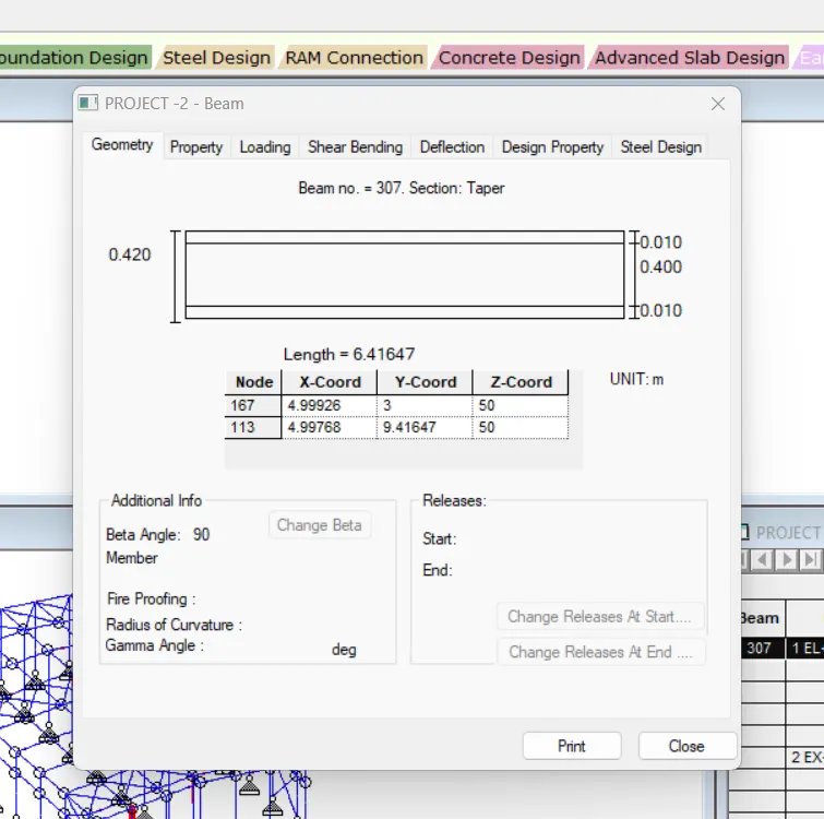
Foundations using STAAD Foundation.
RESULTS:
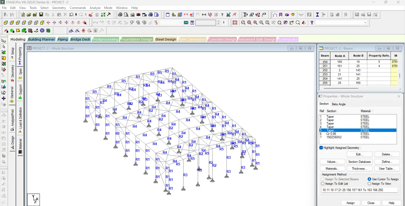
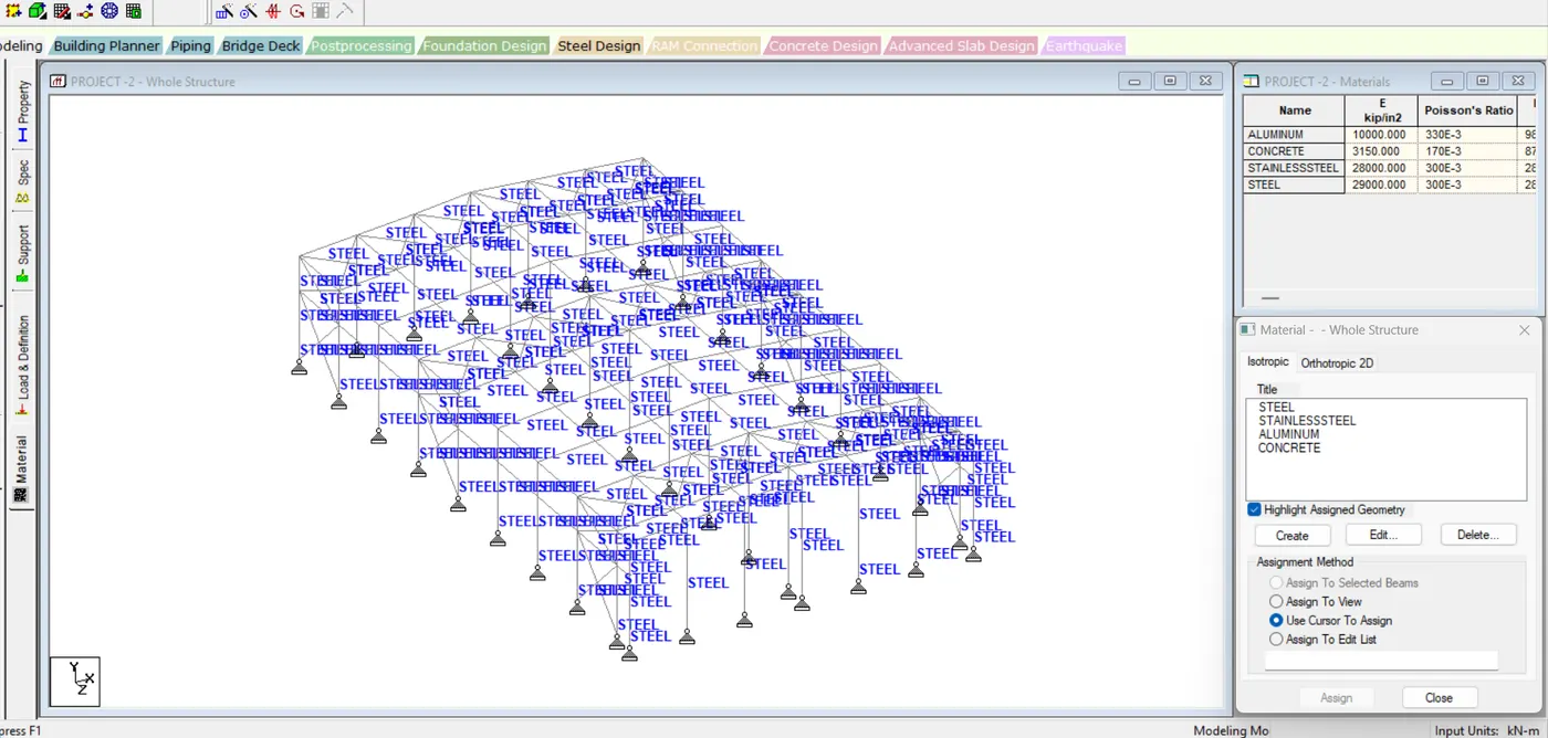
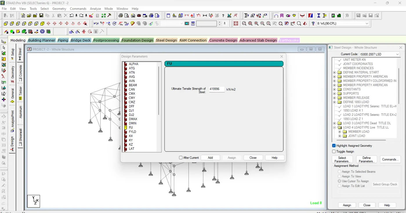
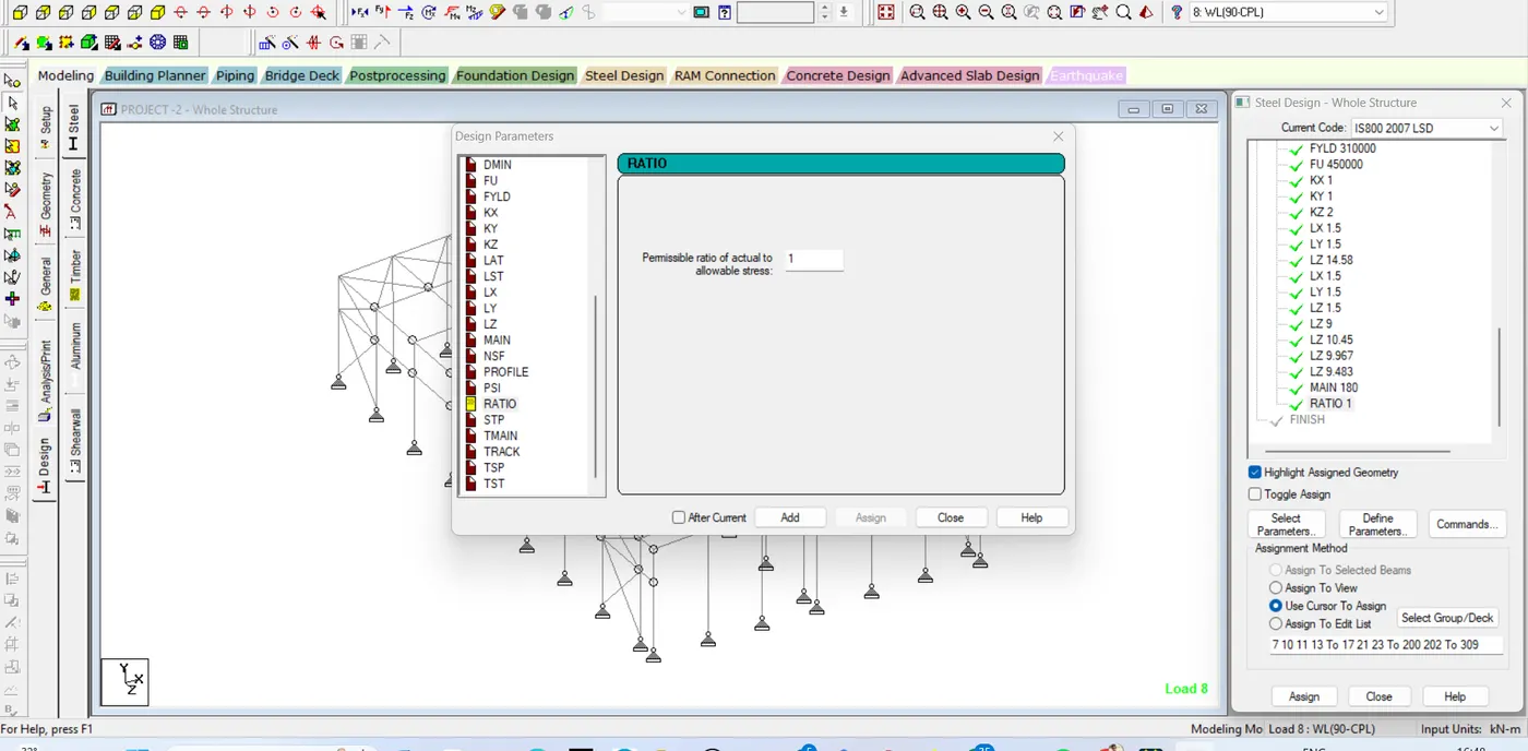
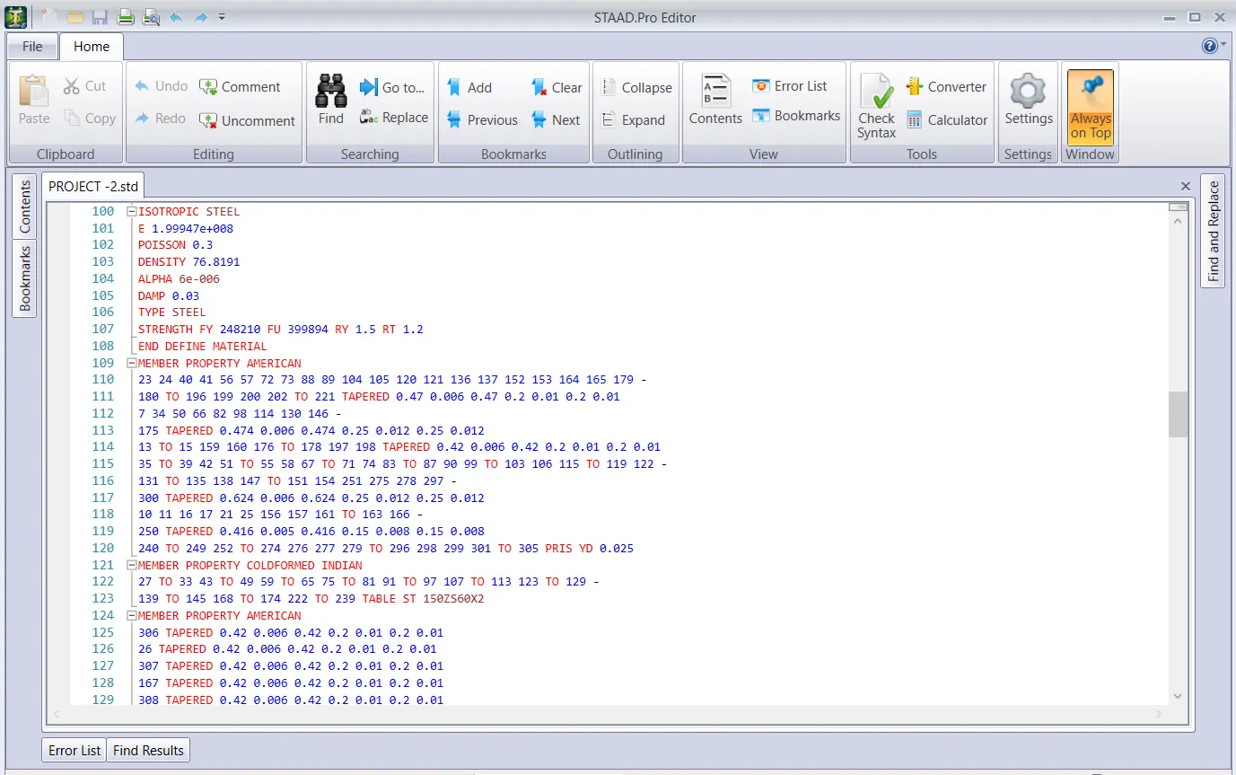
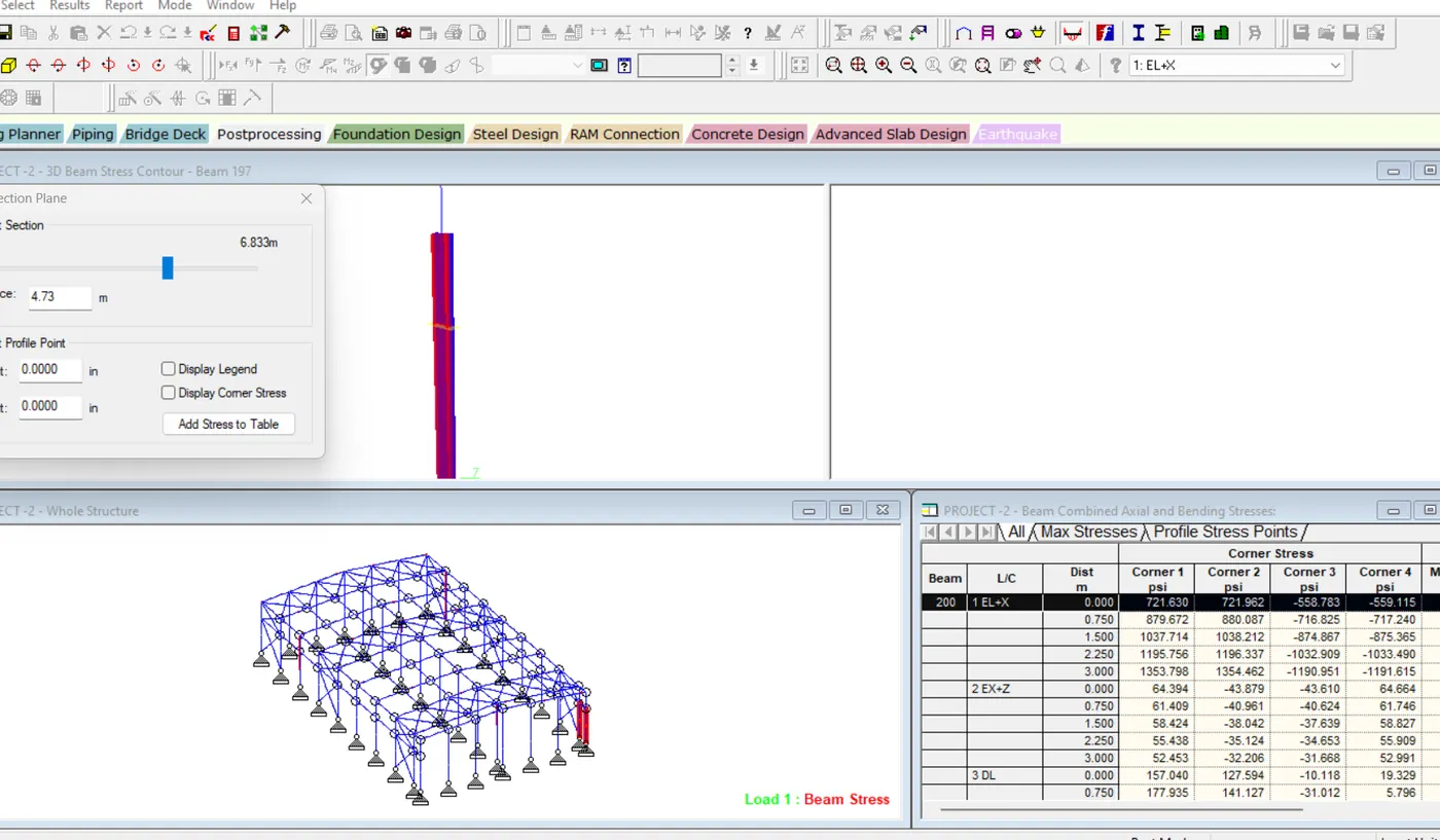
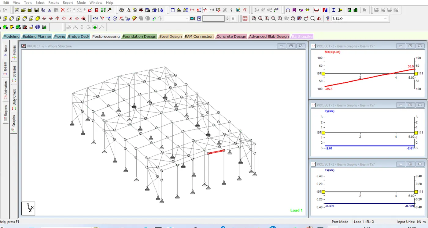
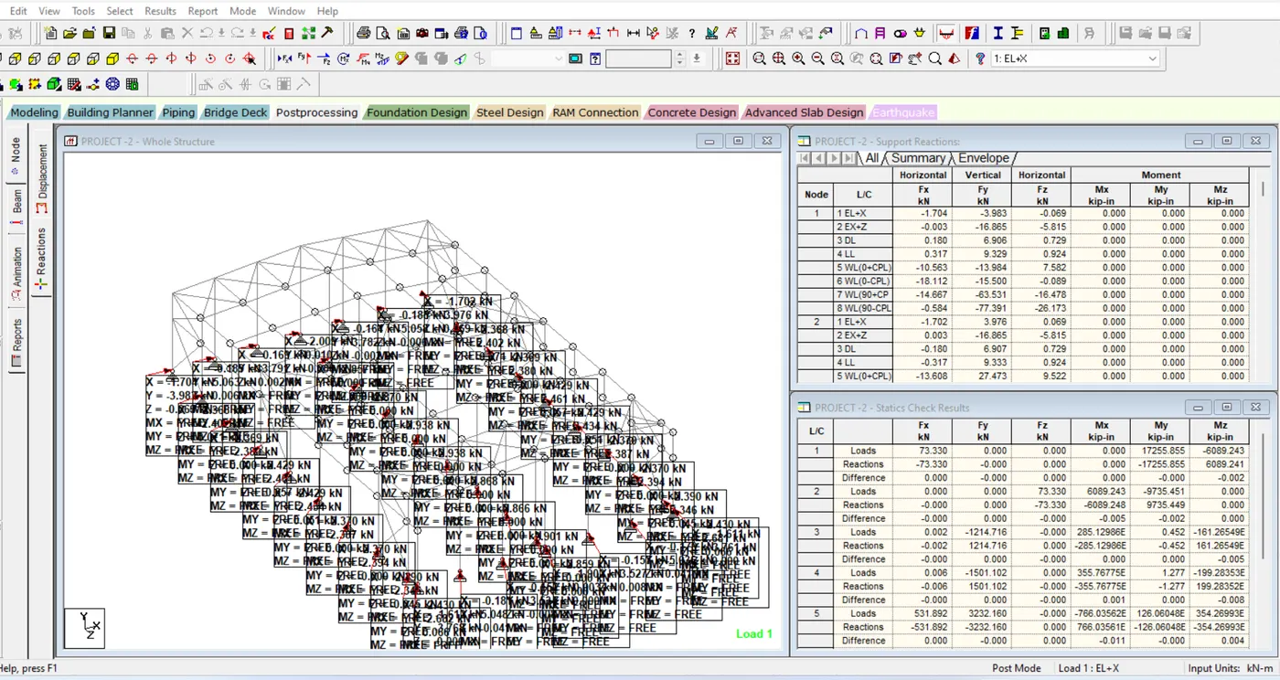
- First analyze the file .
- Analysis Print
2. Design a simply supported gantry girder to carry electric overhead travelling crane
Given:
Span of gantry girder = 7 m
Span of crane girder = 9 m
Crane capacity = 250 kN
Self-weight of trolley, hook, electric motor etc. = 40 kN
Self-weight of crane girder excluding trolley = 100 kN
Minimum hook approach = 1.0 m
Distance between wheels = 3 m
Self-weight of rails = 0.2 kN/m
ANS)
Step -1
Span of gantry girder = 7m
span of crane girder = 9m
Crane capacity = 250KN
self -weight of trolley, hook , electric motor etc. 40 KN
Self -weight of crane grider excluding trolley = 100Kn
Minium hook approch = 1.0m
Distance between wheels = 3m
Slef - weight of rails = 0.2 KN/m
Step -2
Maximum moment due to vertical load :
Weigth of trolley +crane capacity = 40 +250 = 290Kn
Self - weight of crane grider excluding trolley = 100KN
For maxlimum reaction on ganty grider , the moving load should be as close the gantry girder as possible.
Reaction at RA = 50KN.
Reaction at RB = 281.875KN.
This load is transferred to ganty girder , through two wheels the wheel base beign 3m.
So load on gantry girder from each wheel = 251KN
factored wheel load = 375.833 KN
Maximum moments due to moving loads occur under a wheel when the c.g of wheel load
Max.moment due to moving loads occur under a wheel whe the c.g of wheel load
Max.Moment ,Me = 634.21KN-m
Momemnt due to impact = 0.25x 333.90 = 83.47-m
Assume self weight of girder = 2KN-m
Dead load due to self weigth +rails = 2+0.2 = 2.2 KN-m
Factored DL = 2.2x 1.5 = 33KN -m
Moment due to DL = 20221KN-m
M due to imact load = 158.55KNm
Factored moment due to all vertical loads Mz= 812.99KNm.
Step -3
Maximum moment due to lateral Load:
Horizontal force transfered to rails = 10% of weight of trolley plus load lifted = (10/100) x (250 +40) = 29KN
This is distributed over 4 wheels.
So, horizontal force on each wheel = 1.5x7.25 = 10.875Kn
For maximum moment in gantry girder the postion of loads is same as earlier except that it is horizontal , hence by proportioning we get,
My = 18.35KN- m
Vertical shear due to wheel loads = 563.75Kn
Impact = 140.94KN
Self weight =9.90KN
Total shear = 714.59KN
Lateral shear due to surge = 20.68KN
Shear force :
For maximum shear force on the grider , the trailling wheel should be just on the girder as shown below.
Vertical shear due to wheel loads = 230.83+(230.83 x 3)/ 7 = 329.75KN
Step- 4
Prilimary section determination :
Minimum economic depth D = L/12 =7000/12 = 583.33mm
Width of the compression flange may be taken as (L/40) to (L/30) of span
do, flange width can be taken , L/40 = 7000/40 = 175mm to L/30 =7000/30 = 233.33mm
Required plastic modulus Zp = 1.4M/fy
=4552721
=452.72 x 10^3
Let us try a ISMB 600 with ISMC400 on compression flange.
Step-5
Properties of selected section :
ISMB [email protected]/m
A 15600MM^2
h 600mm
b 210mm
tf 20.3mm
tw 12mm
Izz 91800x 10^4mm ^4
Iyy 2650x10^4mm^4
R 20mm
ISMB [email protected]/m
A 6380MM^2
h 400mm
b 100mm
tf 15.3mm
tw 8.8mm
Izz 15200x 10 ^4mm^4
Iyy 508 x 10^4 mm^4
Cyy 2.42mm
Step-6
Let the distance of N>a> from the tension , n range by y
y" = 388.93mm
Izz= 1348.13 x 10^6mm^4
Zez = 3466240mm^3
For compression flange about y - y axis
I = 16766.7 x 10^4mm^4
Zey = 838333mm^3
Total area of section = 21980mm^2
Let plastic N>A>be at a distance
Yp = 580.88
Zpz = 4410317mm^3
For top flange Zpy = 10784888mm^3
Step -7
Section classification :
For ISMB b/t =4.90 <9.4
d/t = 43028 <84
For ISMC b/t = 5.96 <9.4
Hence section is plastic
Step - 9
Check for local moment capacity
Local moment capacity for bending in vertical plane
Mdz = fy zp/1.1
=1002.34Knm
Mdz = 1.2Zefy /1.1
=945.34KNm
For top flange
Mdy = 245.11 KNm
Mdy = 228.6KNm
check for combined local capacity:
(812.99/945.34)+(18.35/228.64)<1
0.947<1
Step -9
Check for buckling resistance:
Md = bzpfbd
Bb =1
Lt = 7000mm
E = 200000n/mm^2
hf = 597.5mm
Iy = 17850 x 10^4mm^4
A = 21980mm^2
ry = 90.12mm
fcr,b = 417.43 KN/m^2
y = 0.744
o = 0.95
fbd = 166.591
Mdz = 734.72KNm
Mdy= 202.84KNm
Hence 1.20>1
Hence section is unsafe against torsional buckling.
Step -11
check for shear:
Vz = 714.59KN
Shear capacity = AVfyw/(3^0.5 x 1.1)
=944755N
=944.755KN > 714.59
Now =566.853KN
Low shear
Check for web buckling:
b = 175mm
n1 =232.6mm
d = 519.4mm
t = 12mm
Fcd = 128.6N/mm^2
Bukling resistance = 629008KN > 714.59KN
Step -13
Check for deflection at working load :
Vertical deflection
Serviceabiity vertical wheel load = 251Kn
Deflection at mid span a = 2000mm
Izz = 1348.13 x 10^5mm^4
& = 25.32mm
Horizontal deflection
I = 16766.65 x 10^4mm^4
& = 4.88mm
L/750 = 9.33mm
Unsafe in vertical direction
safe in lateral direction.