SOLID AND SHELL MESHING ON SUSPENSION ASSEMBLY OF AN AUTOMOBILE
AIM: Perform 2D and tetra meshing and implement connections to the given car rear suspension model
ABSTRACT: In this project will take half section of a car rear suspension system here will perform meshing, tetra meshing on different components with 3D,2D,1D elements along with we will also implement the connections for required areas of bolts, welds, etc..the components with a uniform thickness with less than 5mm will be captured by mid surface extraction technique (i.e 2D ELEMENTS) where the components having more than 5mm thickness will be captured as tetra mesh (i.e 3D ELEMENTS) and coil spring will capture as 1D elements.
METHODOLOGY:
- Import geometry to ANSA.
- Geometrical errors clean up.
- Assign mesh length.
- Assign separate PID's for each component.
- Quality parameter and mesh parameter components with a uniform thickness less than 5mm.
- Defeaturing.
- Shell meshing.
- Volume defining and 3D mesh generation except the mid surface.
- Implementation of connections.
THEORY :
Suspension system: The suspension system of a vehicle refers to the group of mechanical components that connect the wheels to the frame or body. A great deal of engineering effort has gone into the design of suspension systems because of an unending effort to improve vehicle ride and handling along with passenger safety and comfort. The suspension system consisted merely of a beam (AXLE) that extended across the width of the vehicle in the front, the wheel was mounted to the axle end's and the axle was rotated at the center to provide steering. The early automobile's used the one-piece axle design but instead of being rotated at the center, it was fix-mounted to the vehicle through spring's to provide the cushioning of shock load's from road inaccuracies. The wheels were rotationally mounted at the axle ends to provide steering. The first springs consisted of thin layers of narrow pieces of strip steel stacked together in an elliptical shape and were called leaf spring's were replaced by coil springs in the front-engine rear-drive vehicles. The front beam axle was replaced by independently mounted steerable wheels. The wheels were supported by short upper and lower hinged arms holding them perpendicular to the road as did the previous axle beam design. A coil spring was used to support either the upper or the lower arm to provide dampening shock absorbers began to used to dampen shock loads and also to provide resistance to spring oscillations. Later it was learned by shortening the upper arm wheel tilt (camber) could be controlled to prevent edge loading tires while cornering the power transmitting drive axle in the rear served as the beam-type suspension with dampening provided by either leaf or coil spring's as well as shock absorbers. When front-engine front-drive passenger cars were introduced, the upper arm was rotated up and replaced by a member called a "STRUT" which contained the concentrically mounted spring and shock. This arrangement provided additional space for transverse-mounted engine/transmission modules and the front driveshaft.
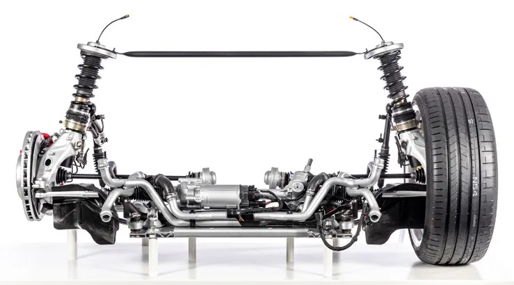
The rear suspension of a car
COMPONENTS OF CAR SUSPENSION SYSTEM :
- WHEEL HUB :
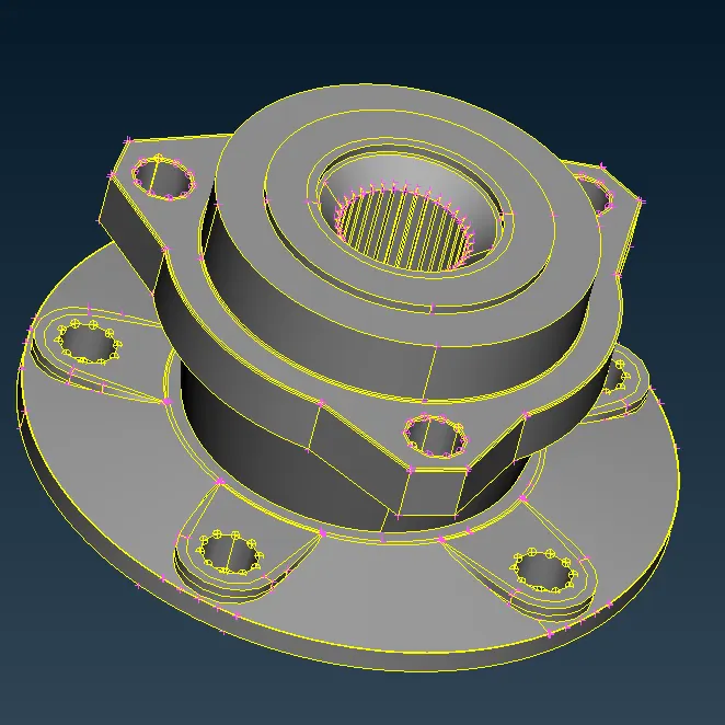
This provides a secure mounting surface for the wheel rim and tire assembly. Wheel hub also contain the wheel bearing's that provide smooth wheel rotation with reduced friction wheel bearing's must have a minimum amount of end play to greatly reduce wheel lateral movement the wheel hub and bearing assemblies must carry the load supplied by the vehicle weight and these assemblies must also guide the wheel and tire assembly.
- STEERING KNUCKLE :
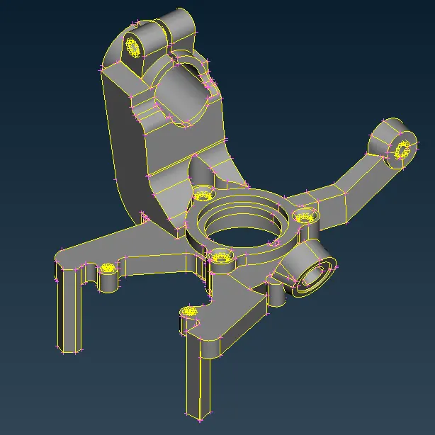
It supports the wheel, tire, brake, and spring weight of the vehicle. It can be mounted in a variety of ways for both front and rear suspensions. The steering knuckle also has an attachment point for the outer tie rod end. A wheel bearing or set of bearing's mount to the steering knuckle to provide mounting of the wheel hub. It's also called spindles. The spindle portion of the steering knuckle is where the wheel bearing and brake components are mounted. The spindle supports those components and allow's the wheel to rotate on the wheel bearing.
- CONTROL ARM (WISHBONE ):
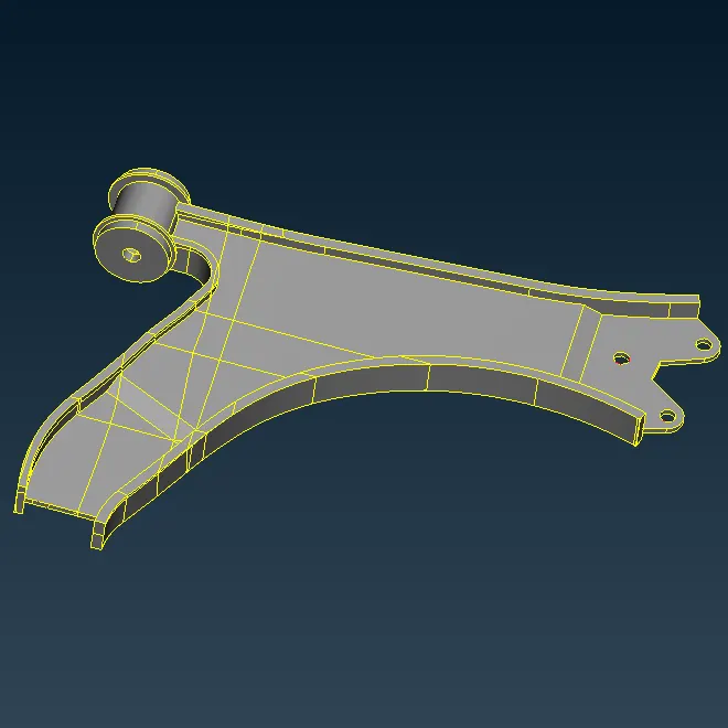
It's used to control wheel movement used on both front and rear suspension, they are commonly referred to by their position. Such as the upper and lower control arms. Its also called wishbones due to their similarities to being wishbone-shaped. A-arms typically have two connecting to the steering knuckle. The control arm mounts to the frame with bushings. These bushings allow up and down movement of the arms.
- BALL JOINT :
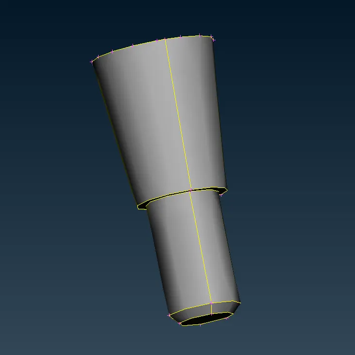
Ball joints allow the steering knuckle to pivot for the steering while providing a tight connection to the control arm and preventing any unwanted up's and down's movement. Ball joint uses a socket joint to allow a wide range of motion similar to a shoulder and a hip joint.
- SPRING :
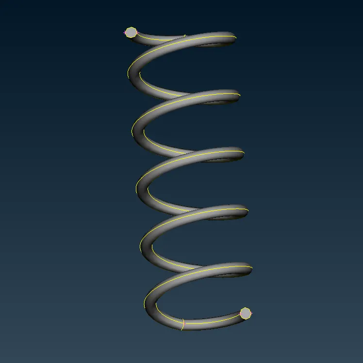
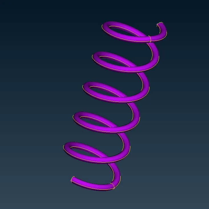
The spring in the suspension has two important functions. Spring supports the vehicle weight and absorb's the bump's and movements that occurs when driving.
- SHOCK ABSORBER :
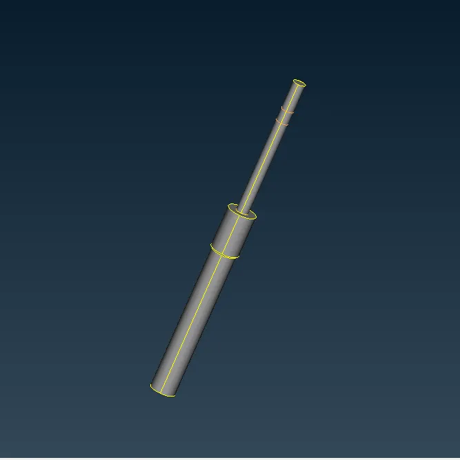
It's a device that controls unwanted spring motion through a process known as dampening shock absorber to slow down and reduce the magnitude of vibratory motion. The upper mount of the shock absorber connects to the frame i.e Sprung weight the lower mount connects to the axle near the wheel.
- STRUT :
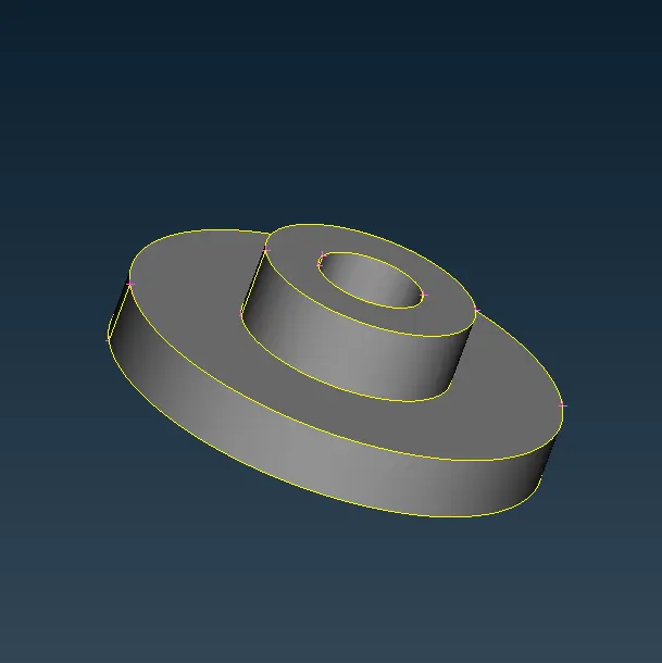
It's basically a shock absorber mounted inside a coil spring. Struts perform two job's they provide a dampening function like a shock absorber and another they provide structural support for the vehicle suspension.
- SWAY BAR :
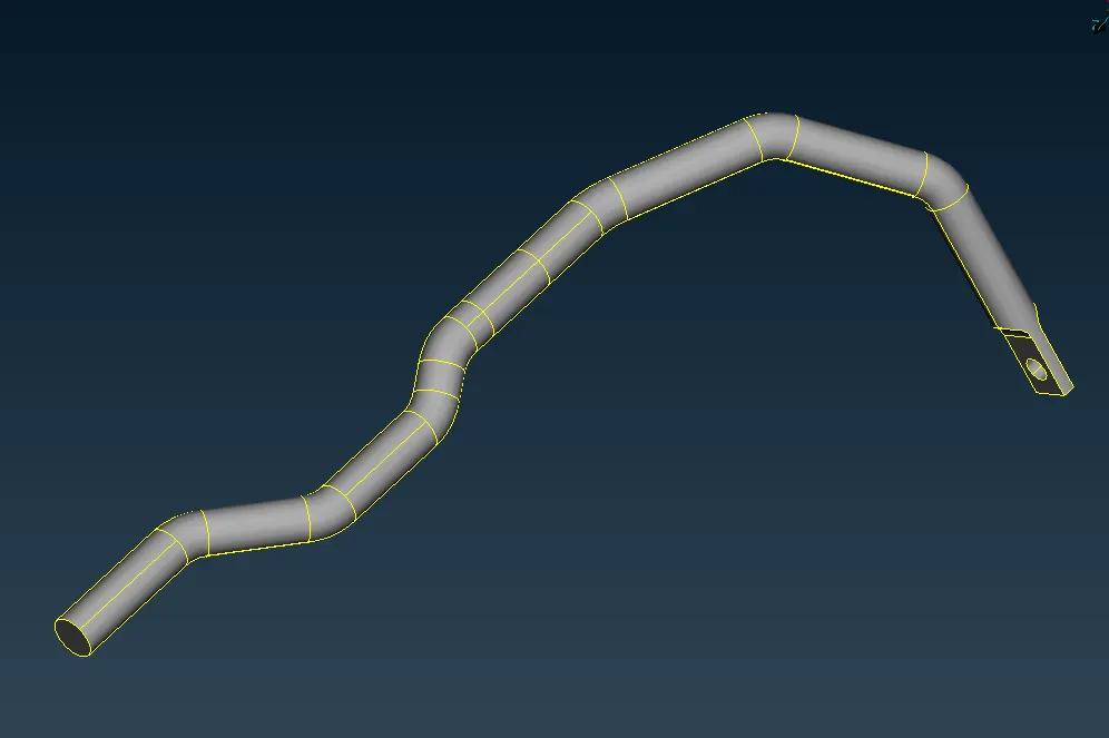
It's used along with a shock absorber or strut to give a moving automobile additional stability. It spans along the entire axle and effectivity joins each side of the suspension together these are also called stabilizer bar.
Quality Criteria for Tria Elements (Tyre and Rim):
|
S.No |
Quality Criteria |
Value |
|
1 |
Target/Average length |
6.5 |
|
2 |
Minimum Length |
5 |
|
3 |
Maximum Length |
10 |
|
4 |
Skewness |
45 |
Quality criteria for Mixed elements (For Midsurface only):
|
S.No |
Quality Criteria |
Value |
|
1 |
Target/Average length |
4 |
|
2 |
Minimum Length |
2 |
|
3 |
Maximum Length |
6 |
|
4 |
Aspect |
3 |
|
5 |
Warpage |
15 |
|
6 |
Skewness |
45 |
|
7 |
Jacobian |
0.7 |
|
8 |
Minimum Quad Angle |
45 |
|
9 |
Maximum Quad Angle |
135 |
|
10 |
Minimum Tria Angle |
30 |
|
11 |
Maximum Tria Angle |
120 |
Quality criteria for Tria (For other components):
|
S.No |
Quality Criteria |
Value |
|
1 |
Target/Average length |
4 |
|
2 |
Minimum Length |
2 |
|
3 |
Maximum Length |
6 |
|
4 |
Skewness |
45 |
Common Quality Criteria for Tetra elements are:
|
S.No |
Quality Criteria |
Value |
|
1 |
Tet-collapse |
0.2 |
PROCEDURE :
STEP 1: Import model to ANSA
STEP 2: Geometrical cleanup
STEP 3: Assign mesh length
STEP 4: Assign separate PID's
STEP 5: Quality and Mesh parameter
STEP 6: Mid surface
STEP 7: Defeaturing
STEP 8: Shell meshing
STEP 9: Volume defining
STEP 10: Implementation of connections
STEP 1: IMPORT MODEL TO ANSA
Import the given car rear suspension part into ANSA
FILE >> OPEN >> REAR SUSPENSION MODEL

Importing model
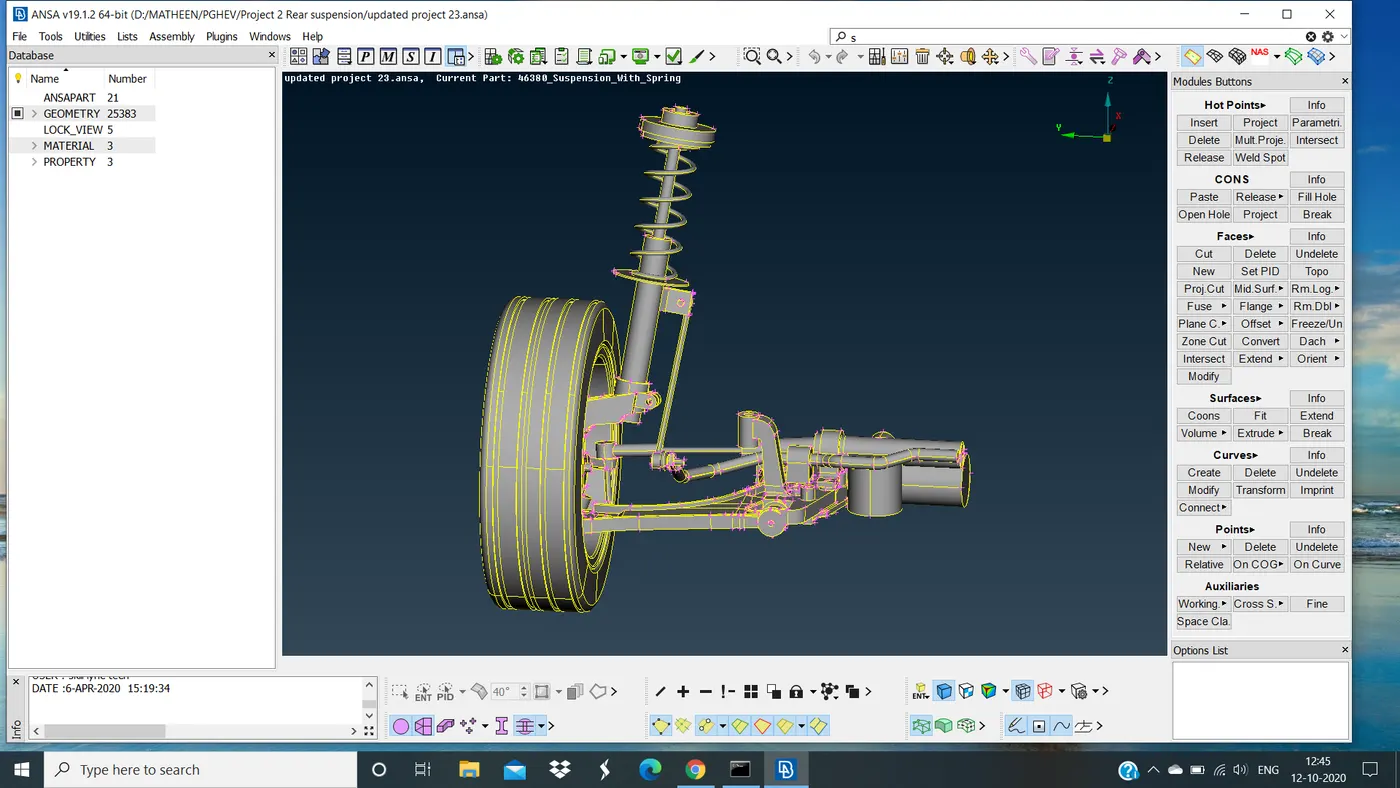
Model import to ANSA
STEP 2 : GEOMETRY CLEAN UP
After importing given model into ANSA check all the geometrical errors for the given model
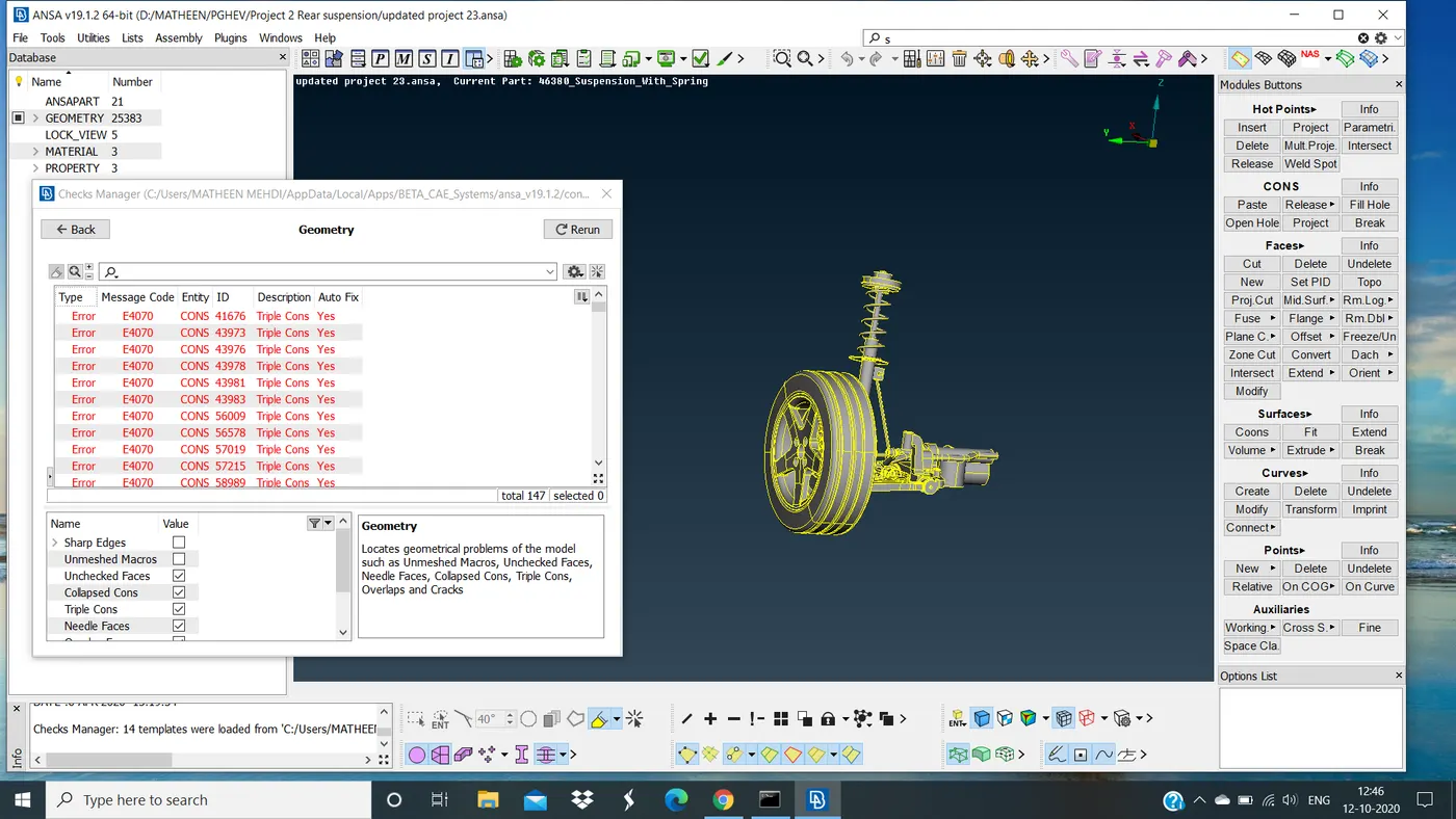
Geometrical errors
Keeping the feature as a single con, triple cons, crack needle face checked, etc. We will see that error's once clicked execute button for proceeding further we need to solve that error's by two method
- Auto fix method
- Manual method
AUTO FIX METHOD: Select all the errors press to right-click on the mouse will see the fix option-click the fix button then some of the errors will be resolved automatically like triple cons etc. But still, we can see some errors that are fixed by the manual method.
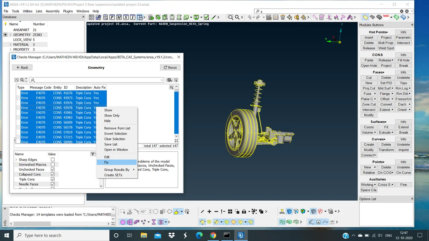
MANUAL FIX METHOD: In this method manual fixing of those errors is done one by one. In this method, we need one by one approach and the error areas are fixed by manually by release con's, deleting faces and recreating new faces, etc. By this, we can solve those errors by manual method.
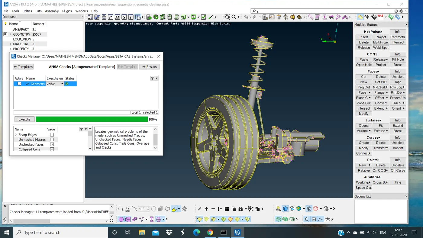
Geometry cleanup
Now the model is error-free proceed for further steps
STEP 3: ASSIGN MESH LENGTH
Here we need to assign a given mesh length
Goto mesh mode >> perimeter >> length >> Set it as 4mm for all components except tire and rim part
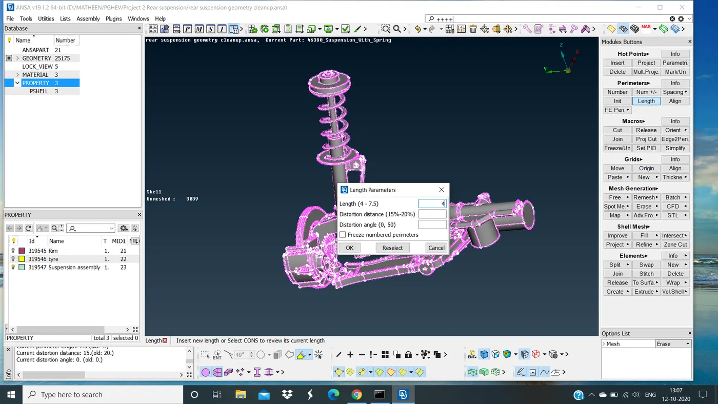
The target length for other components except for tire and rim
For tire and rim set it as 6.5mm
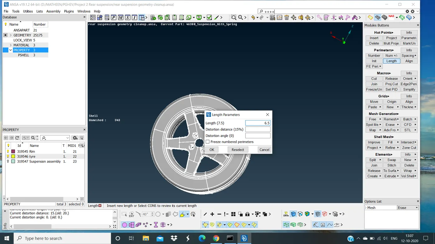
The target length for tire and rim
STEP 4: ASSIGN SEPERATE PID's
Once the model is error-free then we can segregate different parts under property ID so as to proceed part by part
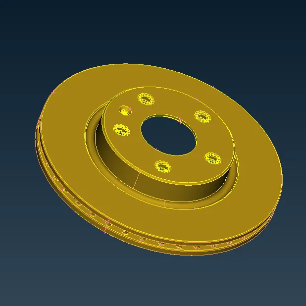
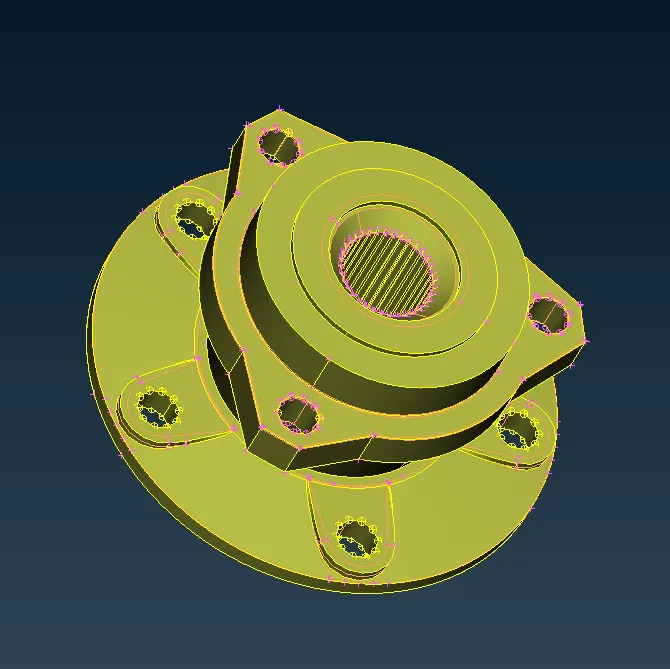
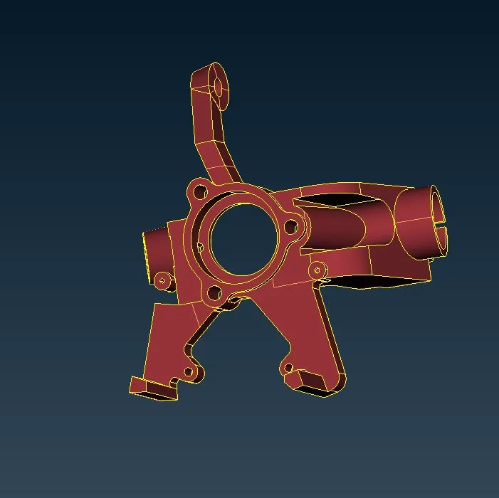
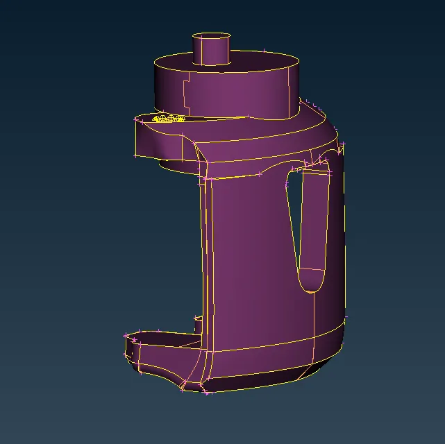
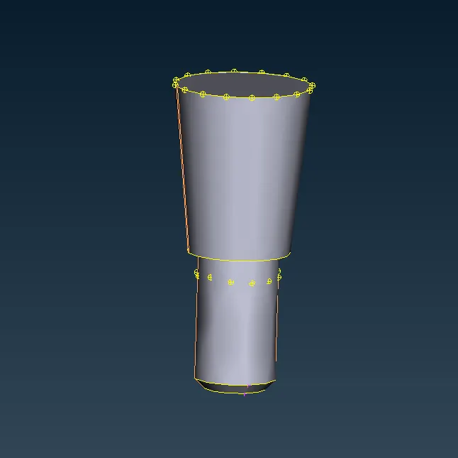
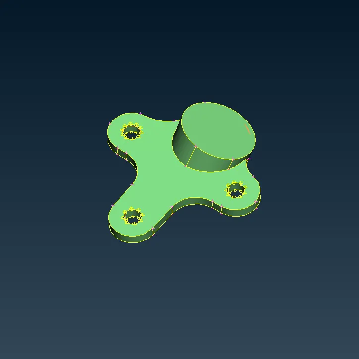

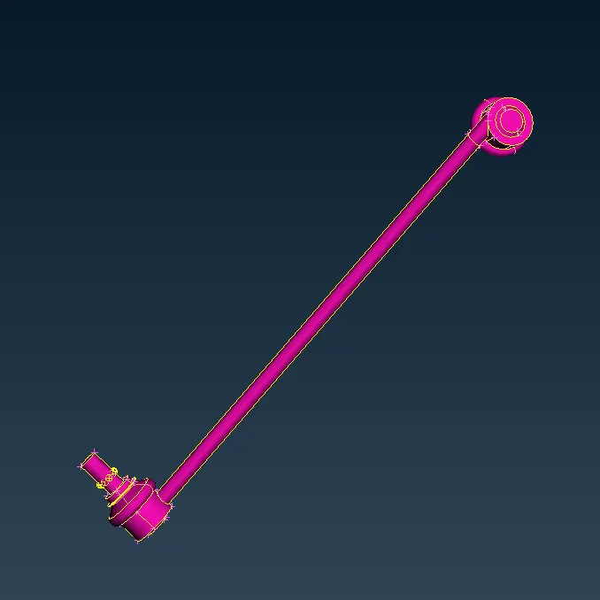
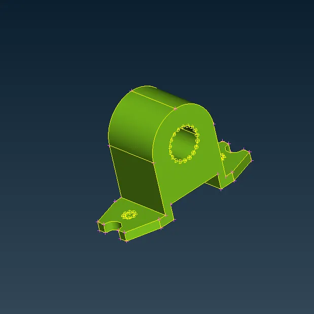
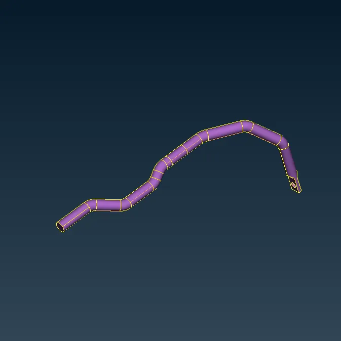
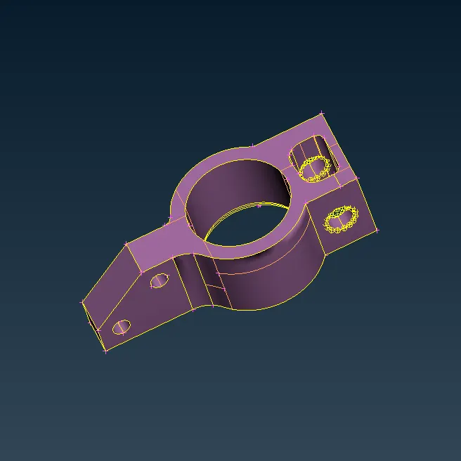
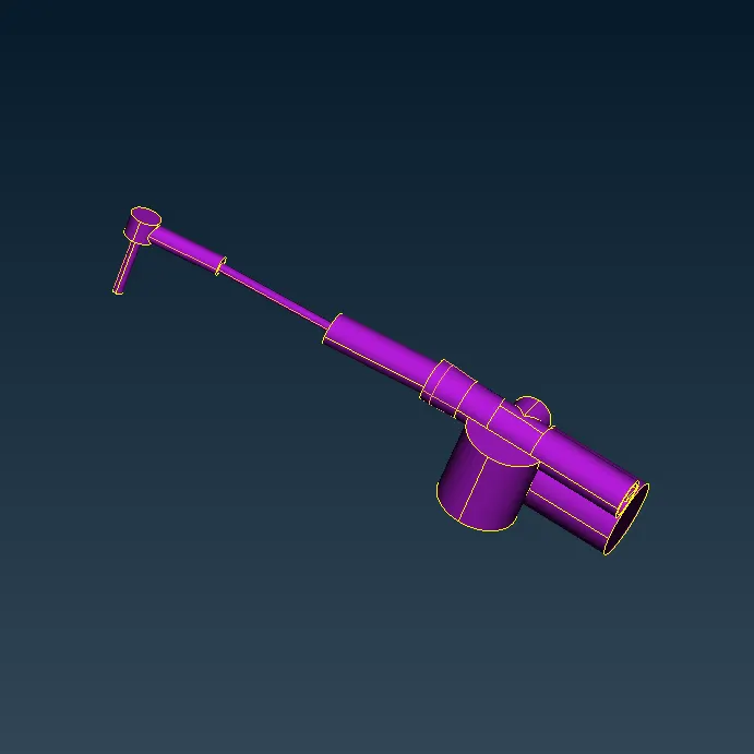
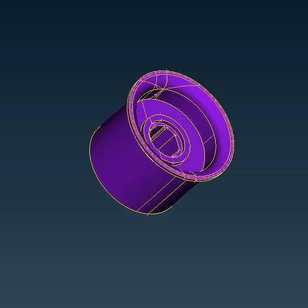
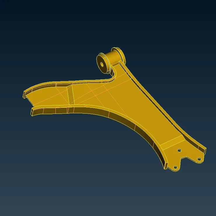
Assigning some new PID
STEP 5: QUALITY PARAMETER AND MESH PARAMETER
Set quality and mesh parameters for a given TIRE and RIM
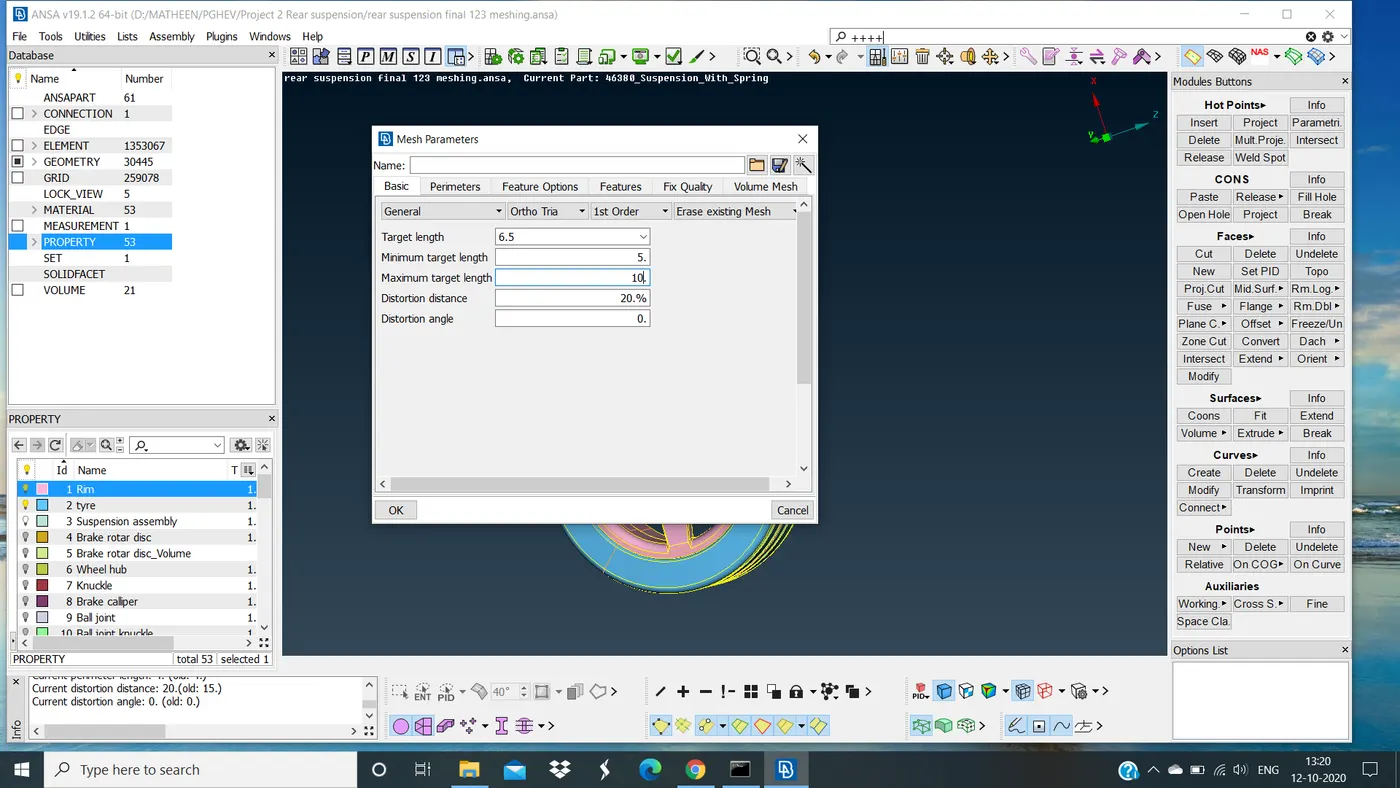
Mesh parameter for Tire and Rim
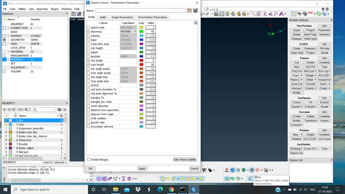
Quality parameter for Tire and Rim
Now set quality parameter and mesh parameter for all other components except Tire and Rim (TRIA AND ORTHO TRIA)
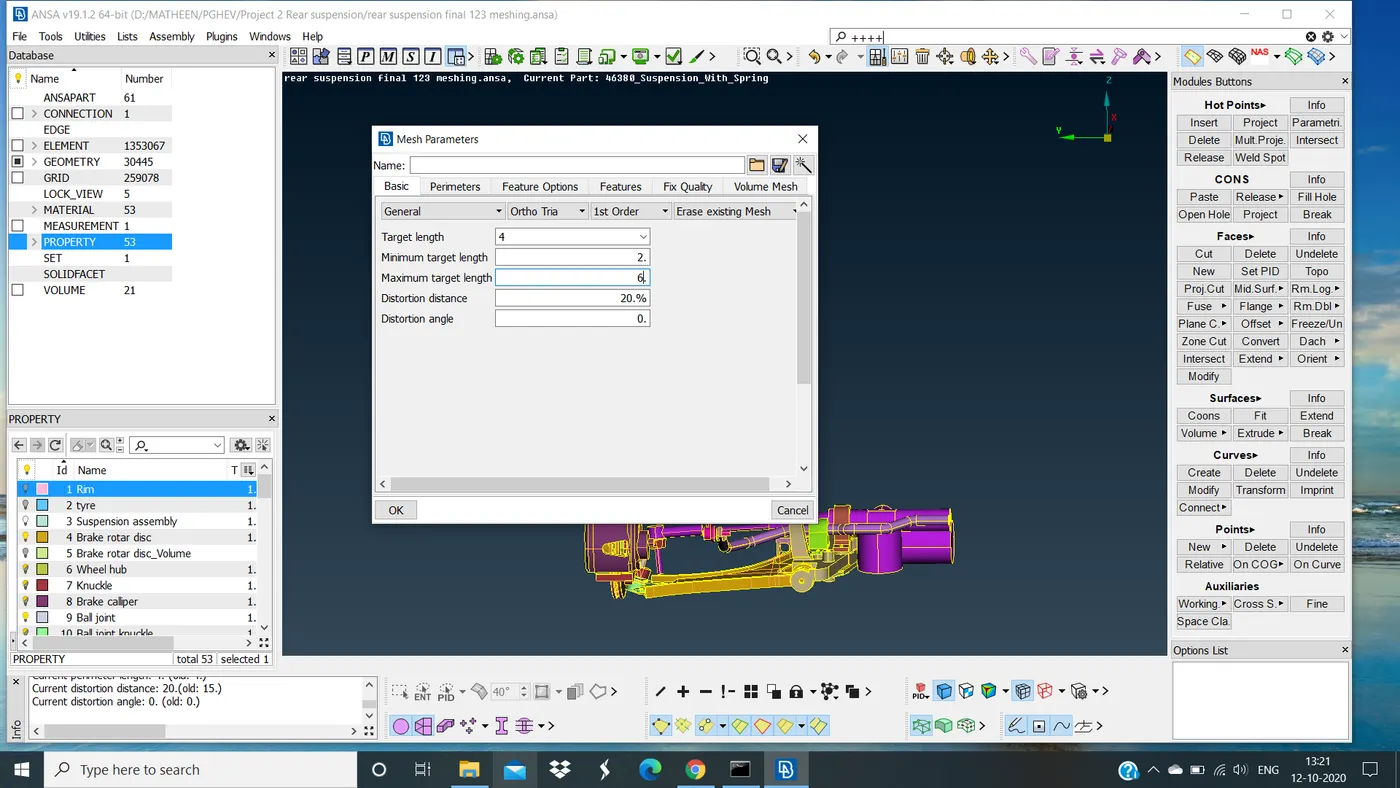
Mesh parameter for other parts except tire and rim
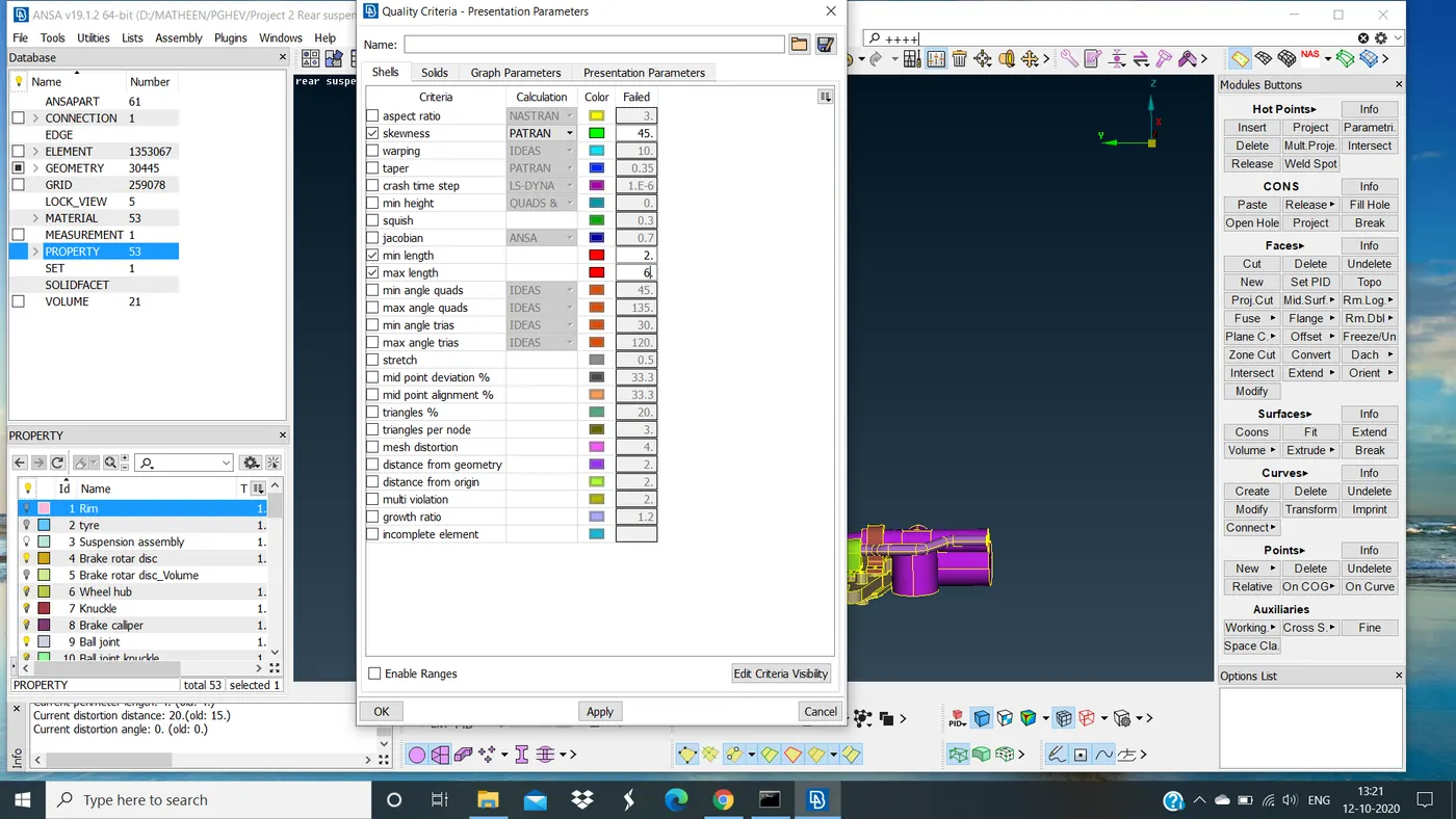
Quality parameter for other components except for Tire and Rim
Now set quality parameter and mesh parameter for components with uniform thickness less than 5mm
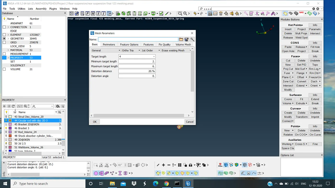
Mesh parameter for thickness less than 5mm
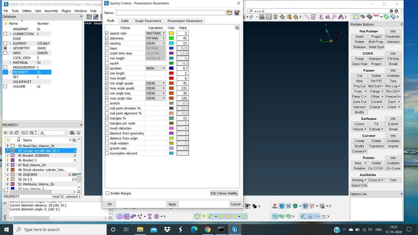
Quality parameter for thickness less than 5mm
Set solid quality parameter for the thickness more than 5mm (TETRA MESH)
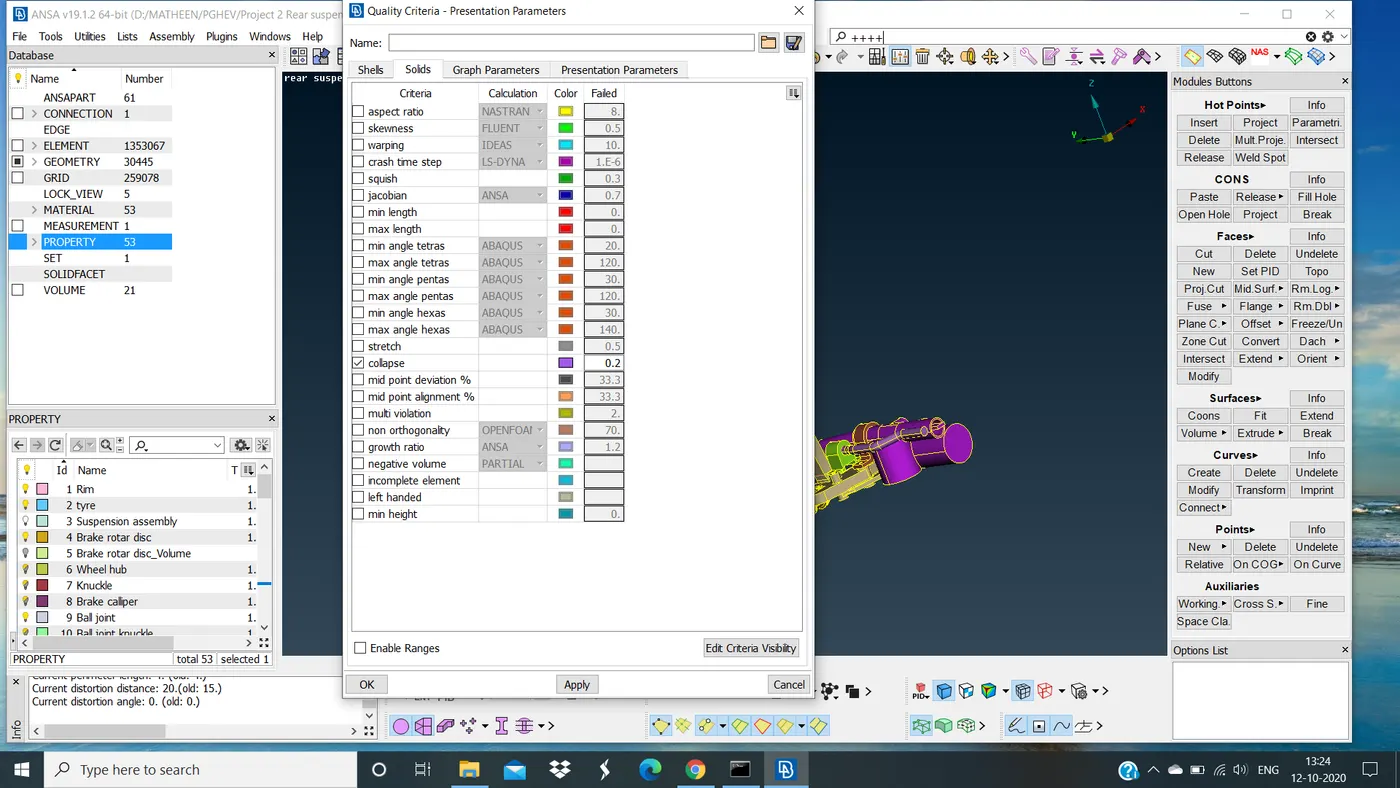
Solid quality
STEP 6: MID-SURFACE
If the components with a uniform thickness of less than 5mm then only we will go for mid surface extraction
There are only three parts that have thickness less the 5mm
Mid-surface can be done by offset, middle, auto-mid, etc.
Mid-surface by auto mid extraction
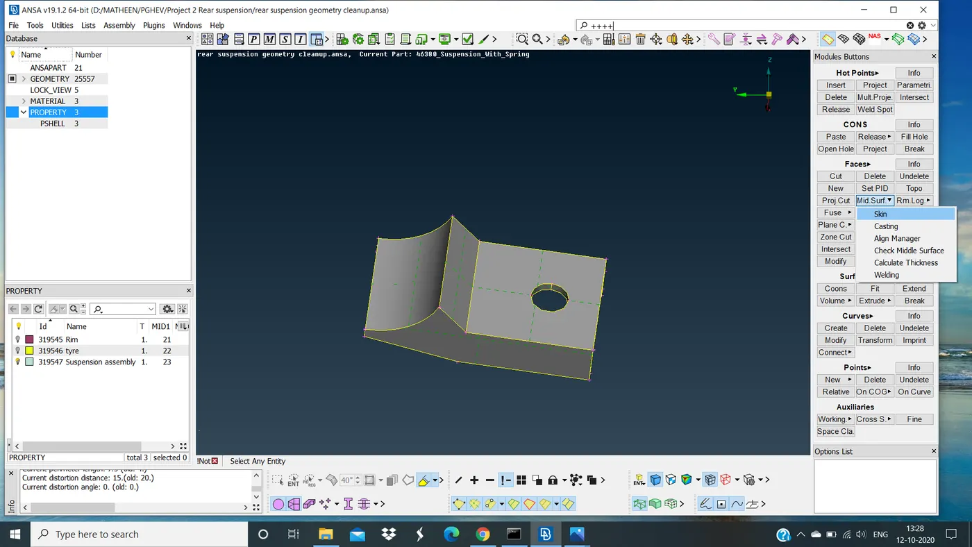
Auto mid by using SKIN
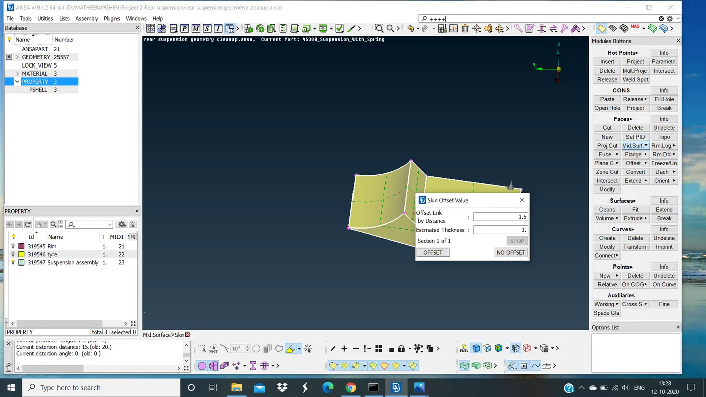
Bracket auto-mid
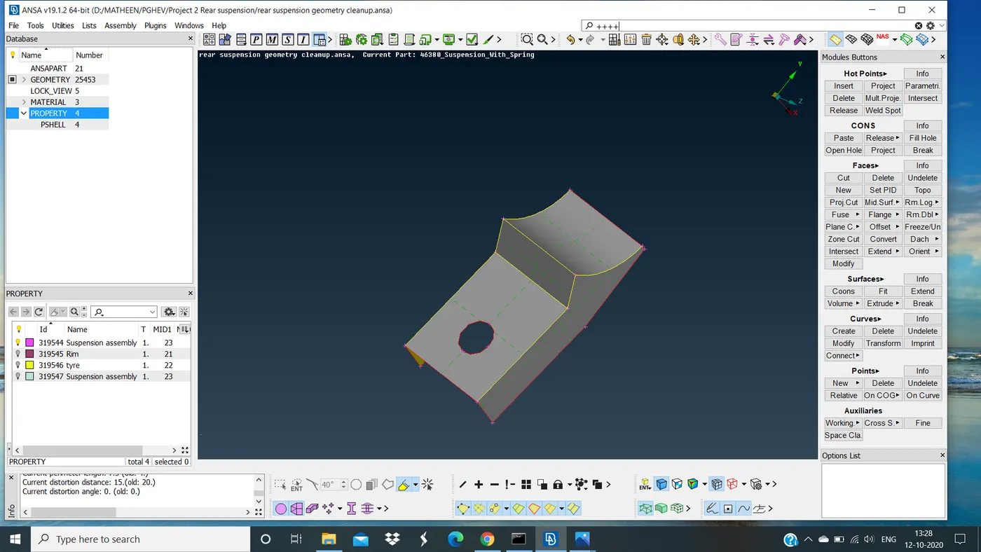
Mid-surface of bracket
Mid-surface of wishbone subpart
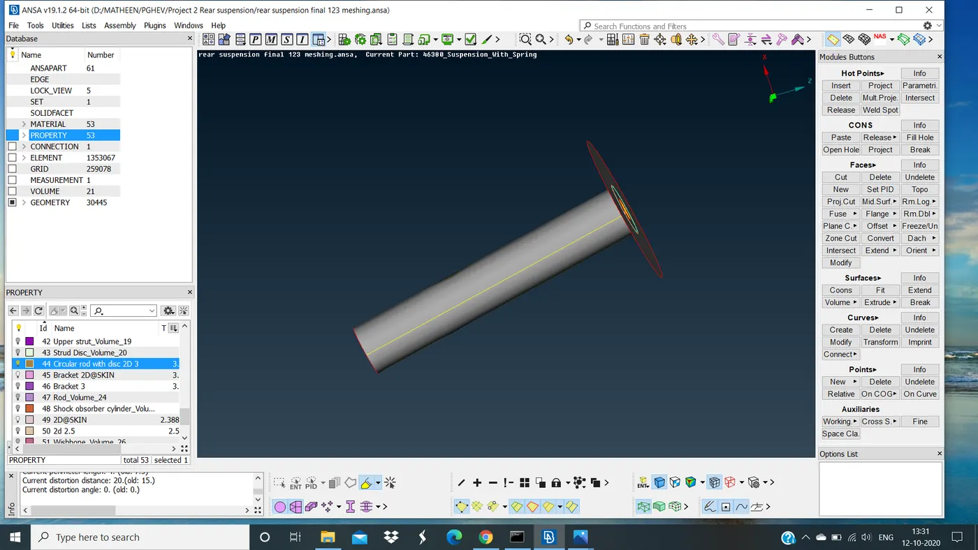
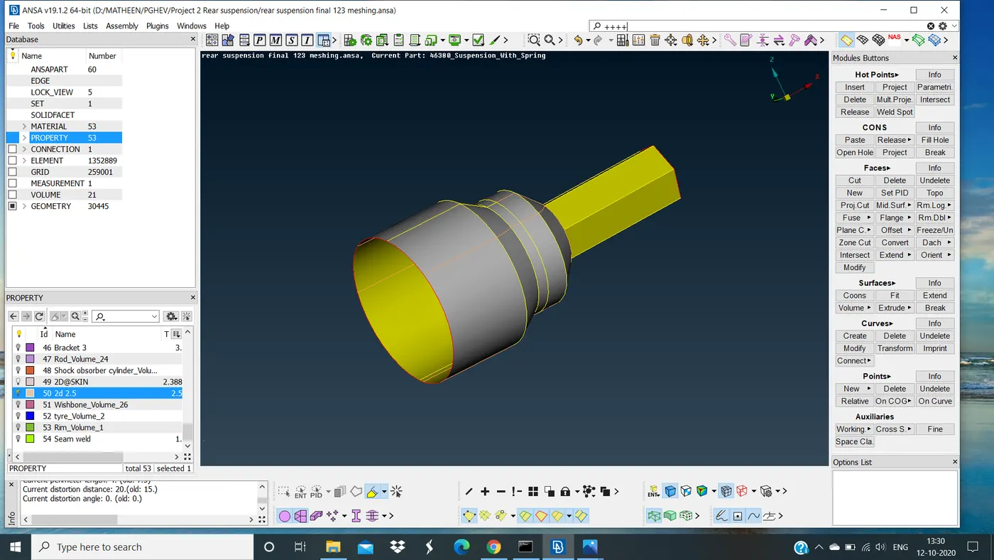
Mid-surface of a circular rod
STEP 7: DEFEATURING
Here we will defeature those double cons which would fail for minimum length. Suppose the distance between two cons is less than minimum length then we have to defeature that line because it will cause the minimum length error's after meshing so we need to defeature those lines
Goto topo mode >> Faces >> Cut
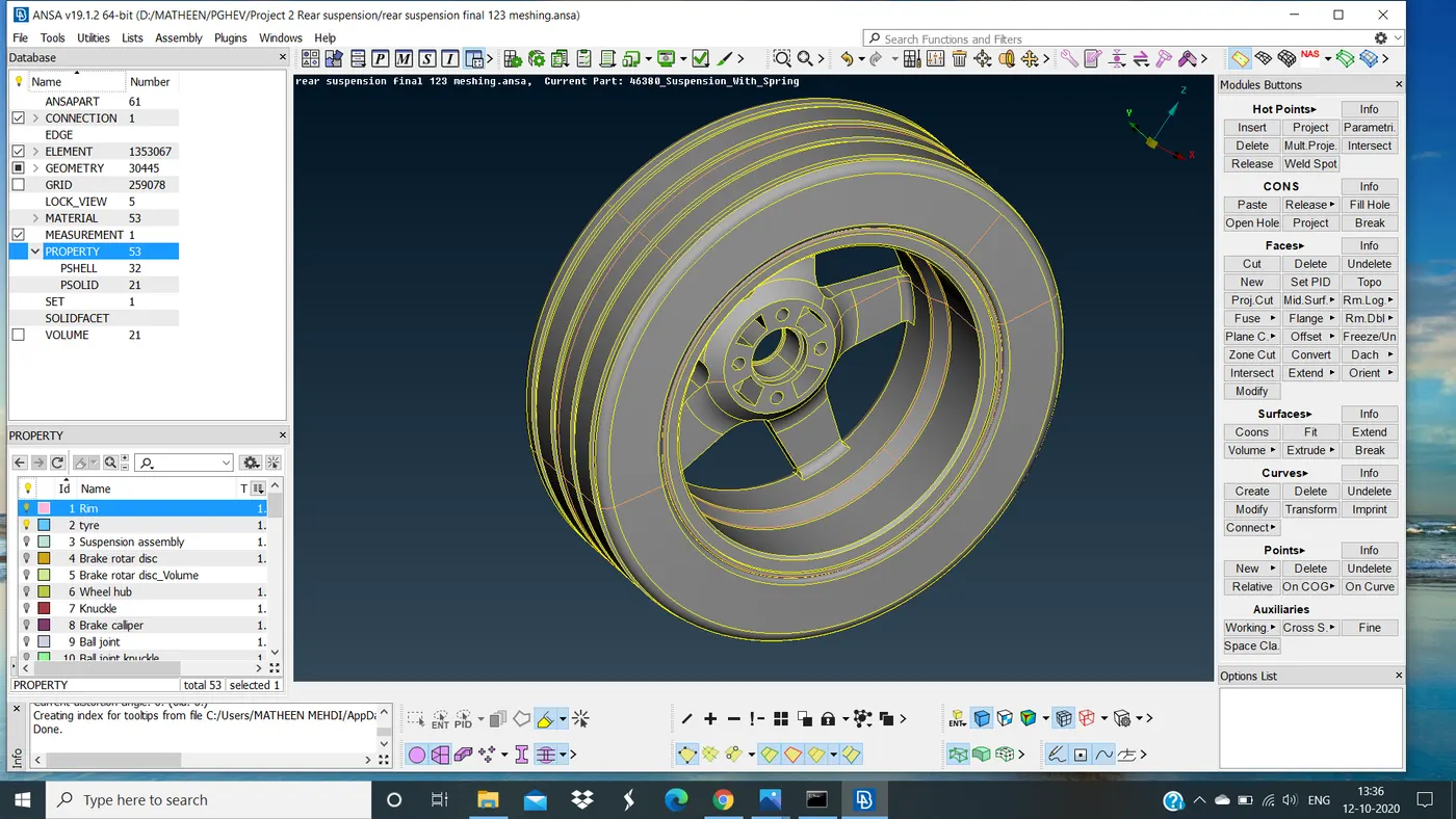
Defeature lines of Tire and Rim
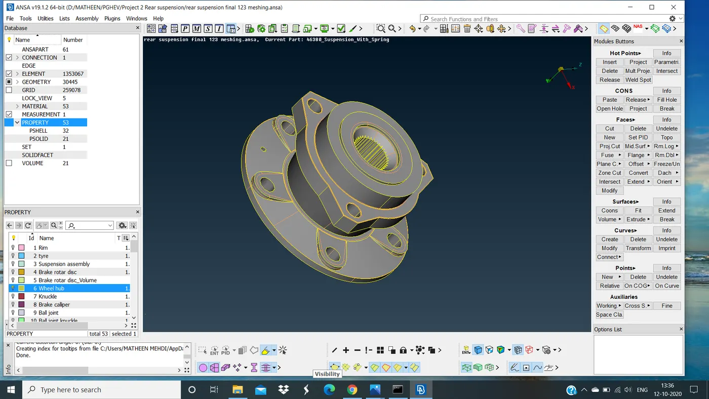
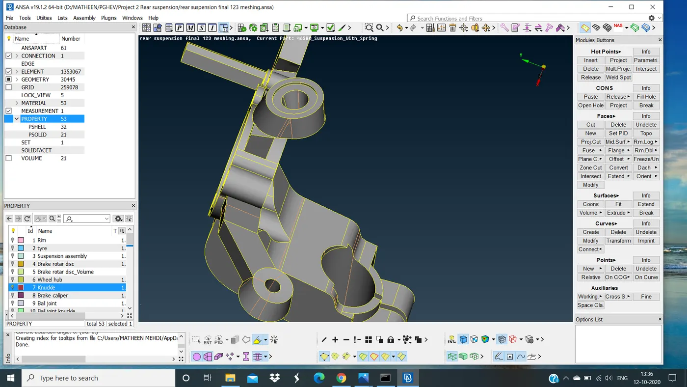
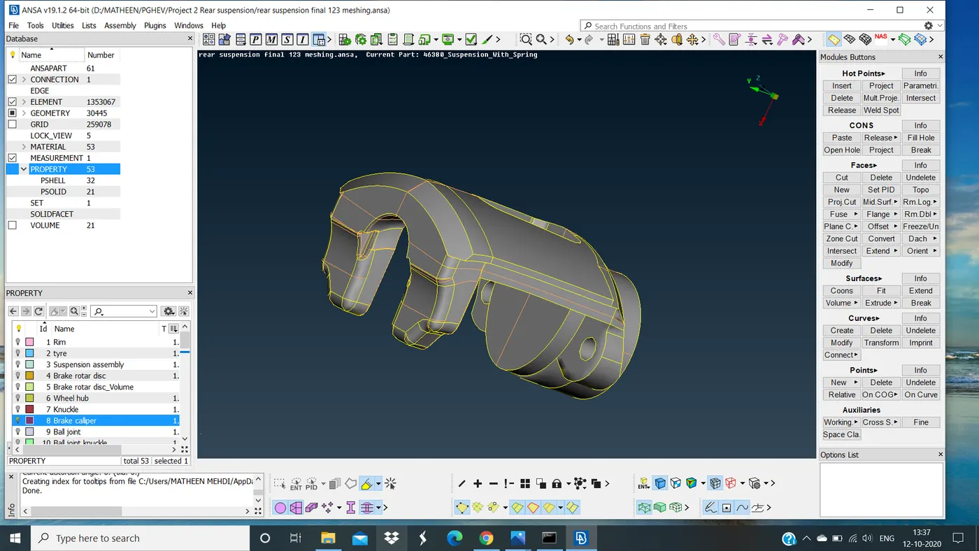
Defeaturing some components which is less than the minimum length
STEP 8: SHELL MESHING
Before selecting any mesh algorithm to mesh we have to set mesh length
Goto >> Mesh mode >> perimeter >> 4mm except tire and rim
Perform mesh with best mesh algorithm it will give best mesh flow
Create a mesh and choose element type as mixed for 2D (Mid-surface)
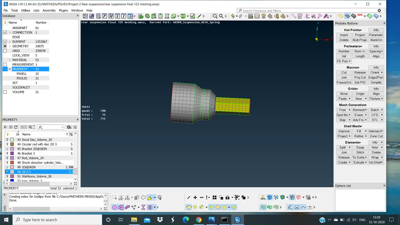
2D mesh of Wishbone part
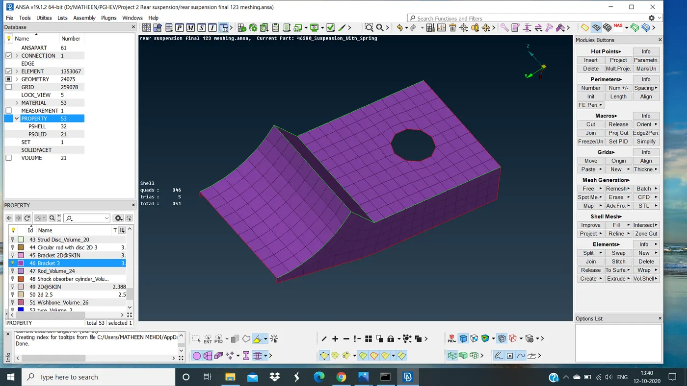
2D mesh of bracket
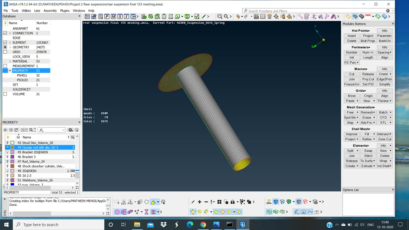
2D mesh of circular rod
Now mesh the solid component's which is having a thickness of more than 5mm
Mesh with the best mesh algorithm it will give the best mesh flow
create a mesh and choose element type as ortho tria
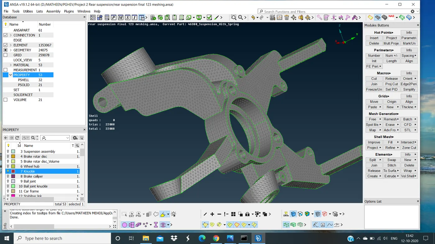
3D Mesh of Knuckle
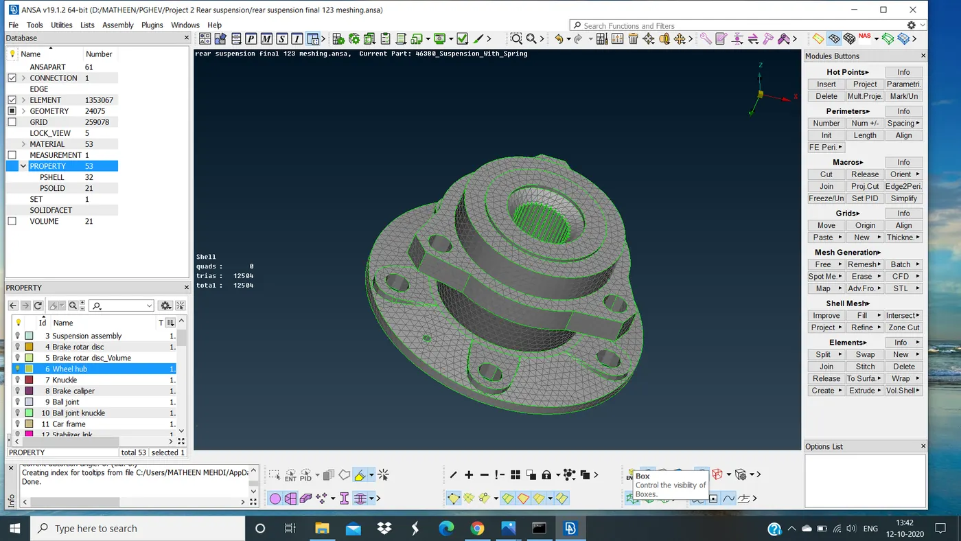
3D Mesh of Wheel hub
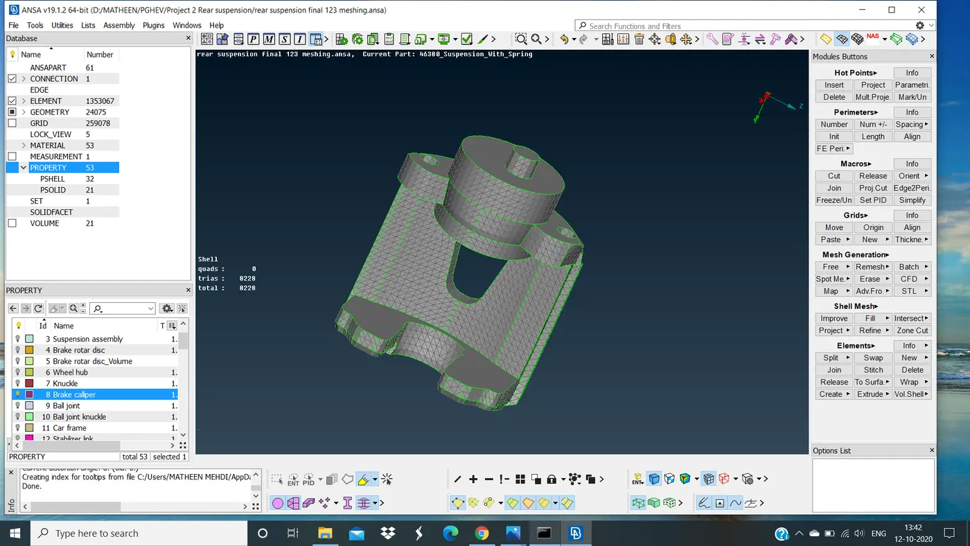
3D mesh of Brake Calliper
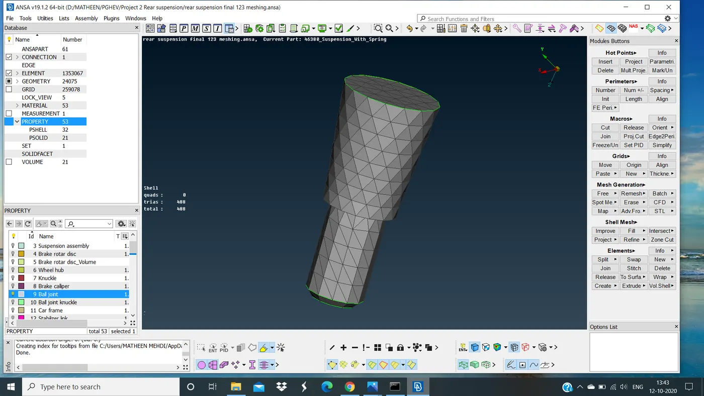
3D Mesh of Ball Joint
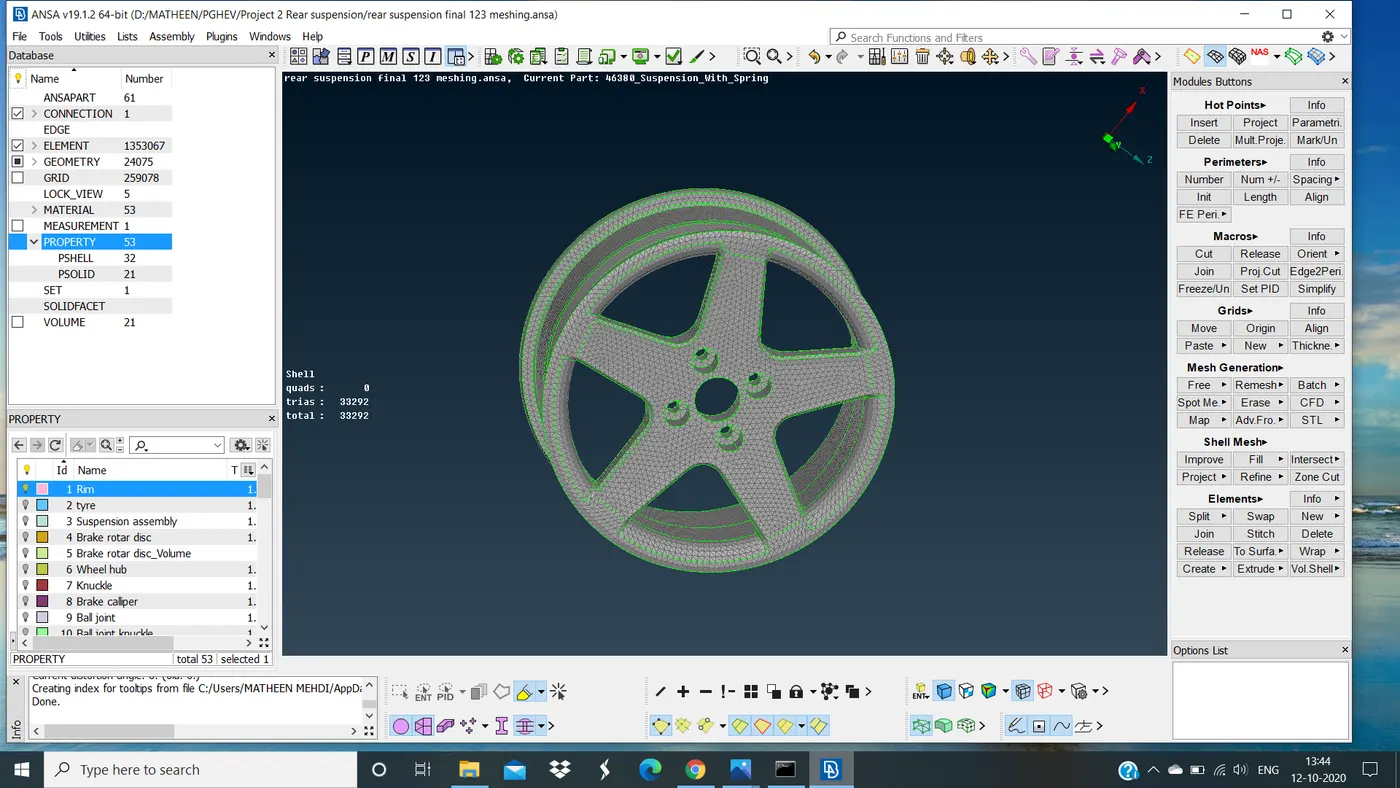
3D Mesh of Rim
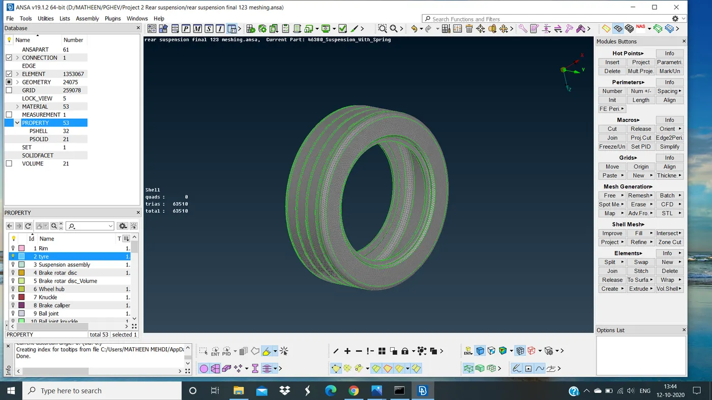
3D mesh of Tire
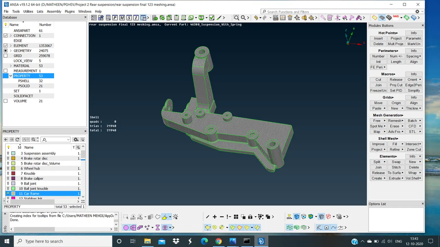
3D Mesh of Car Frame
STEP 9: VOLUME DEFINE
Once the mesh is done we need to define the volume under mesh define >> AUTO
The ANSA will automatically define the volume of all components There we have to remesh the volume parts by using tetra FEM
Check for tet-collapse after volume is generated
Suppose if tet-collapse errors will be their means we have to fix those error's by using FIX QUALITY, MV FREE
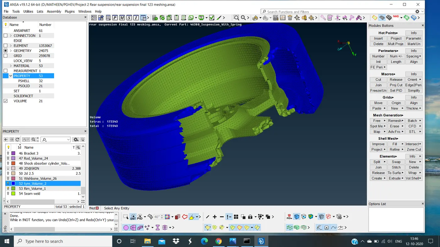
Volume of Tire and Rim
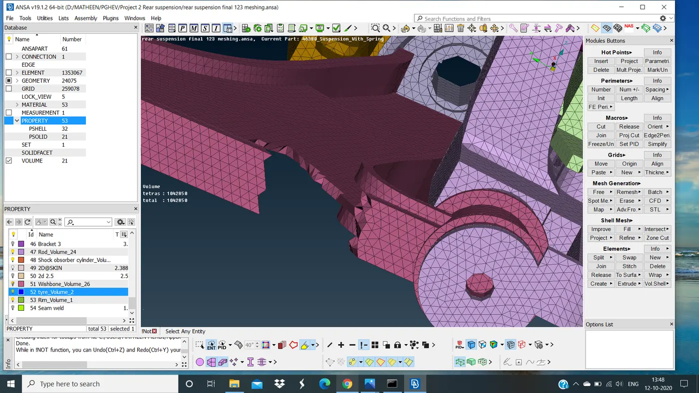
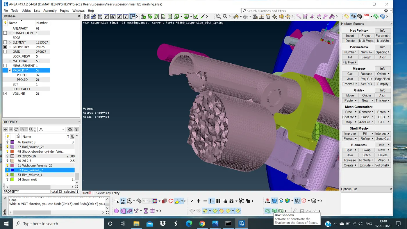
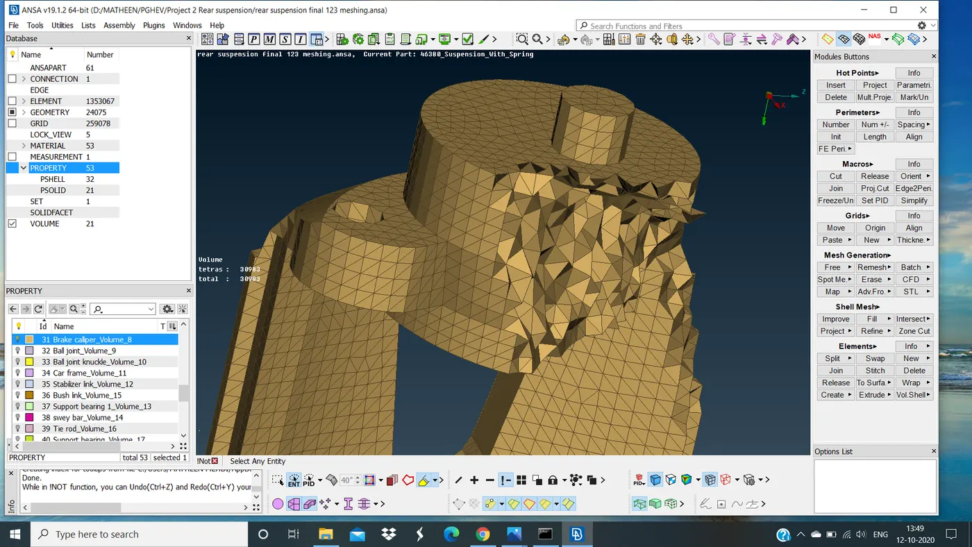
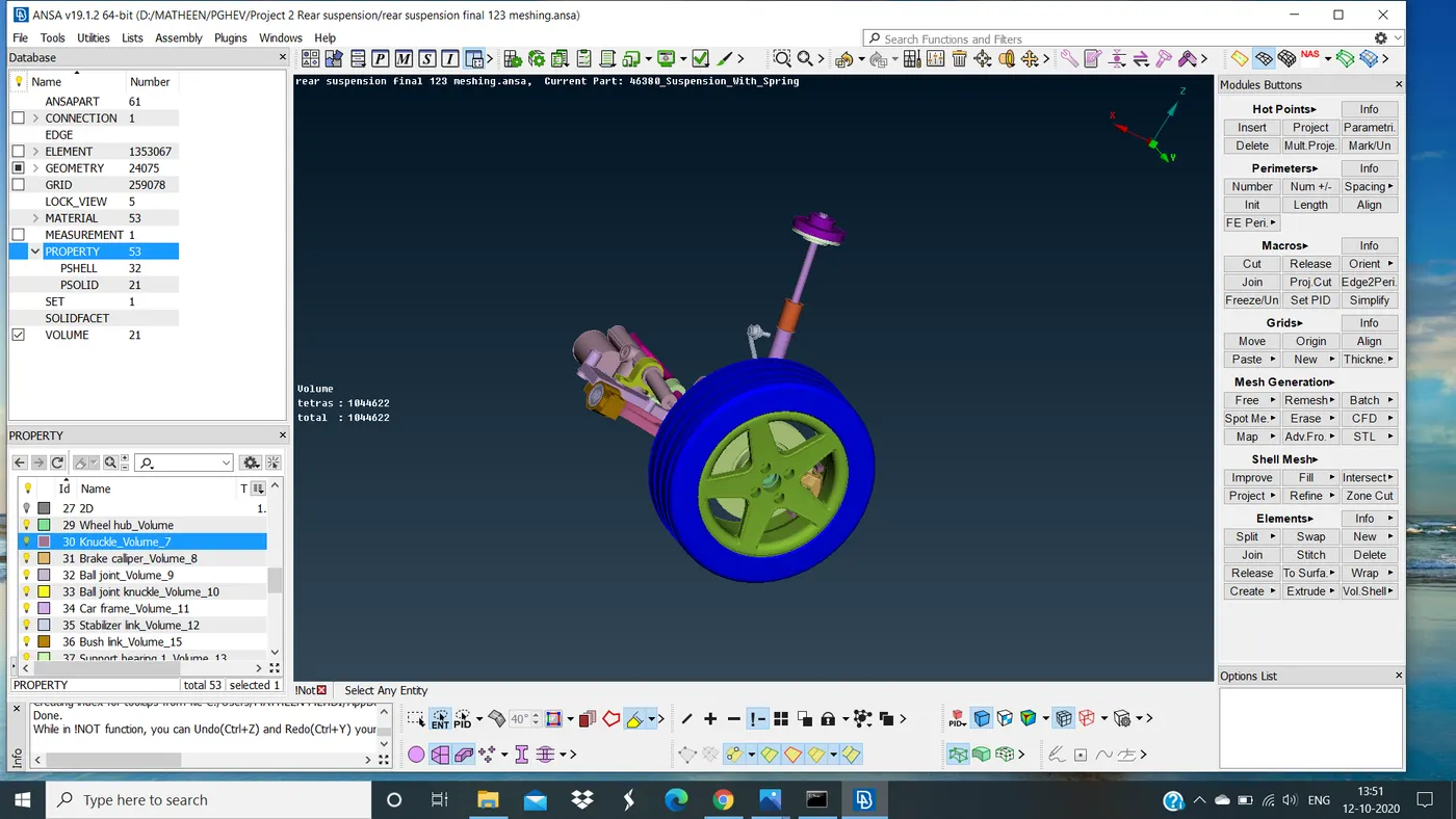
volume of other parts
STEP 10: IMPLEMENTATION OF CONNECTIONS
MANY NODE RBE2
Many node RBE2 is used for the bolt regions
It's used to connect the connection between end nodes
To give the connection here we need to follow some steps
On NASTRAN deck
Goto element module >> Select RBE2 >> Many nodes >> Select slave nodes >> Master node will generate automatically >> On create entity >> Select always ask option >> Create a part in the model browser
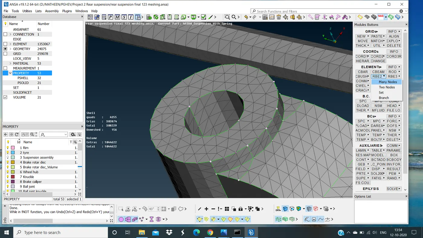
RBE2 Many nodes command
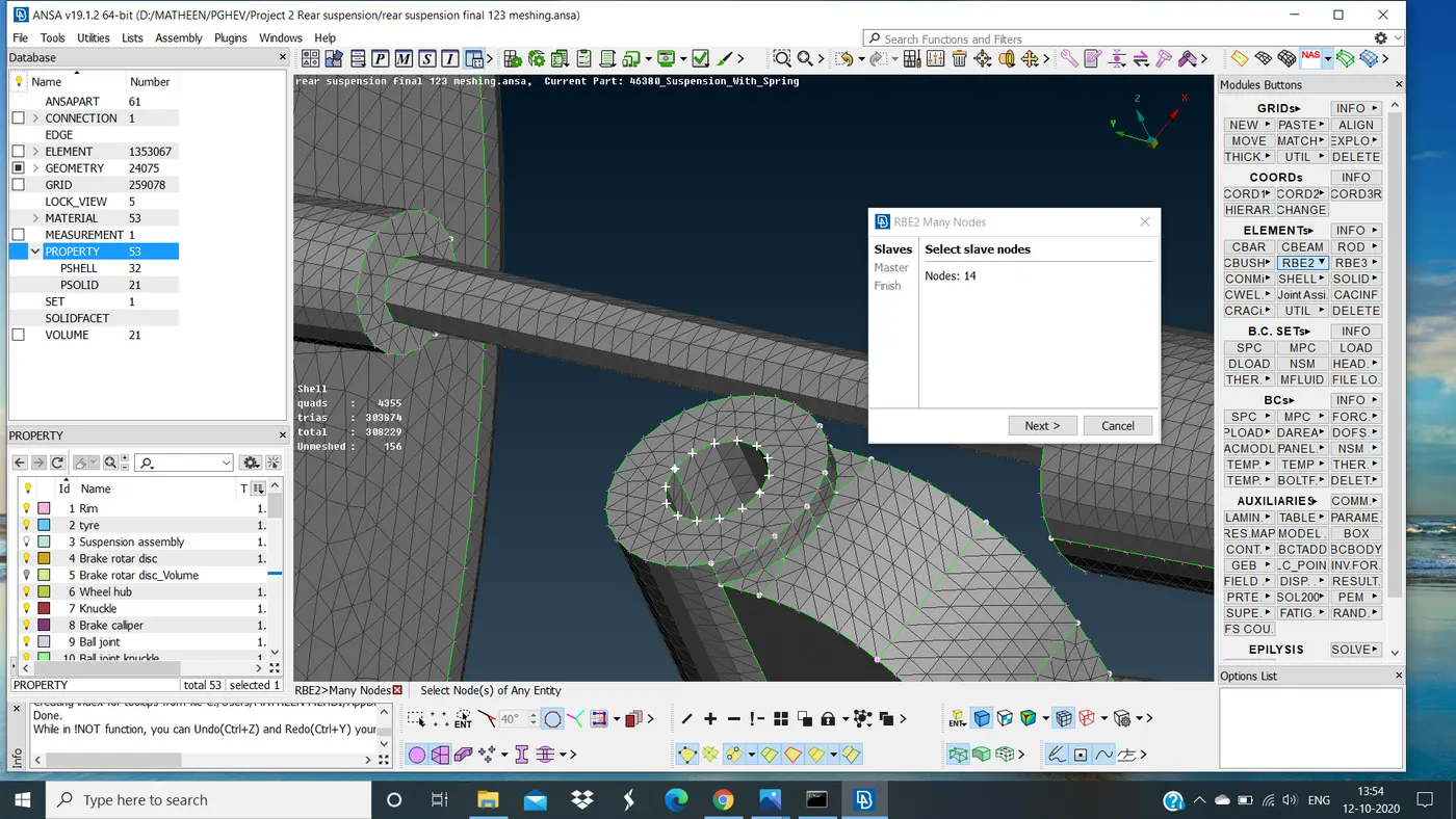
Selecting slave nodes
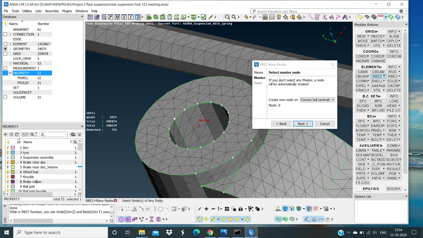
Master node generated
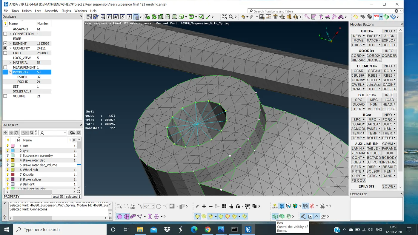
Rigid connection is done by many node RBE2
SINGLE NODE RBE2
The single-node RBE2 is to give the connection between two parts that can be given to the nodes
On elements module >> select RBE2 >> single node >> Select to nodes to be connected
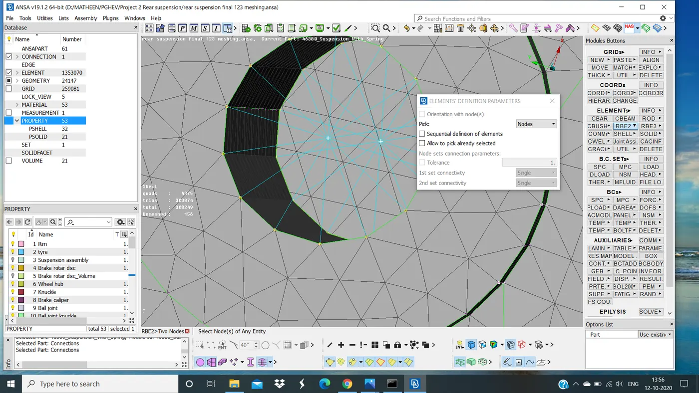
Selecting two nodes
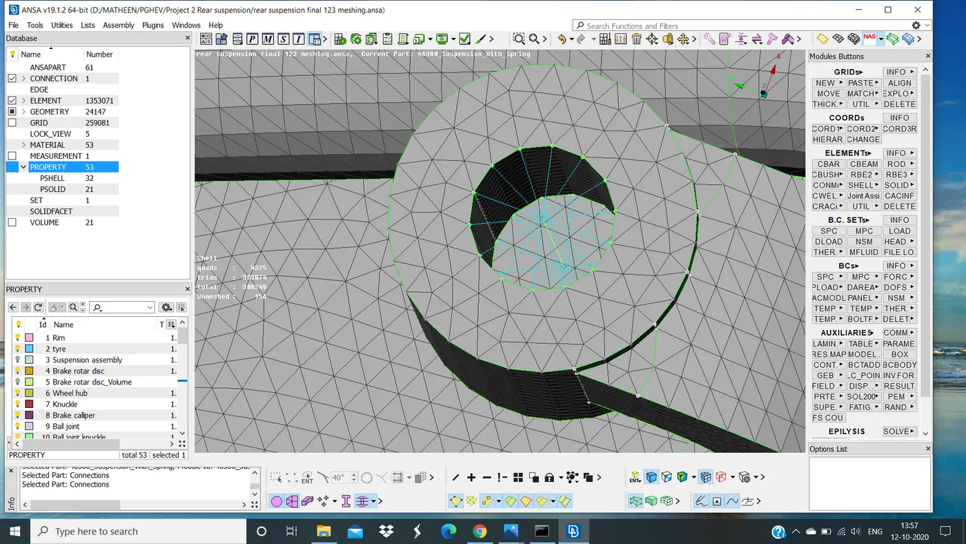
Two node RBE2 connection is generated
SEAM WELD :
To create the connection first we have to measure or take the length of the connection
Create cons2curve under curves
In topo mode >> curves >> cons2curve >> select cons >> middle click >> ok
The curve data needs to be convert to the seam line connection.
Goto assembly manager >> click convert >> select the curve >> select the connection type >> seam line >> seam line is created
Goto assembly manager >> click connection manager >> select the line >> middle click >> select P1,P2 >> select FE rep type as overlap shell >> give search distance >> give width as 4mm as target length >> create new PID >> release >> ok
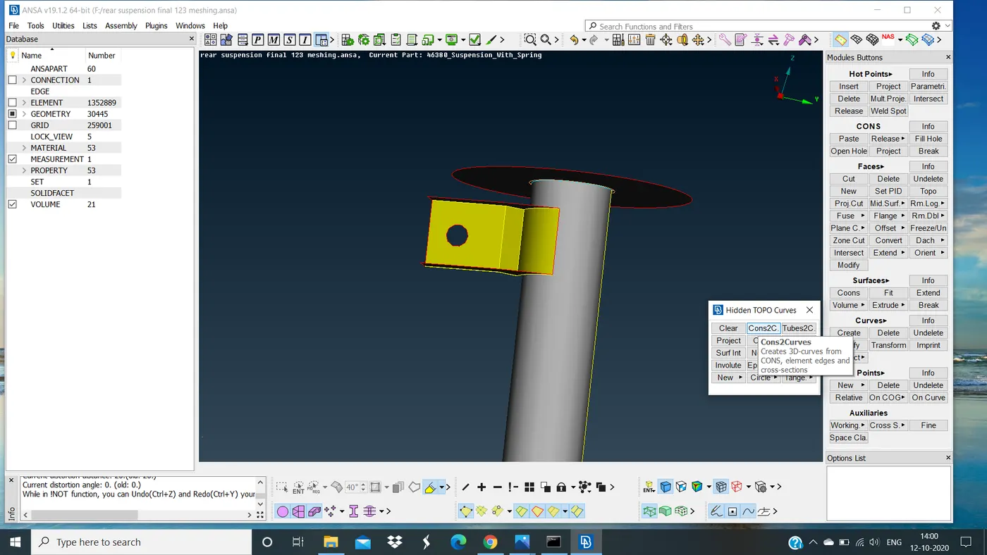
creating a seam line by cons2curve
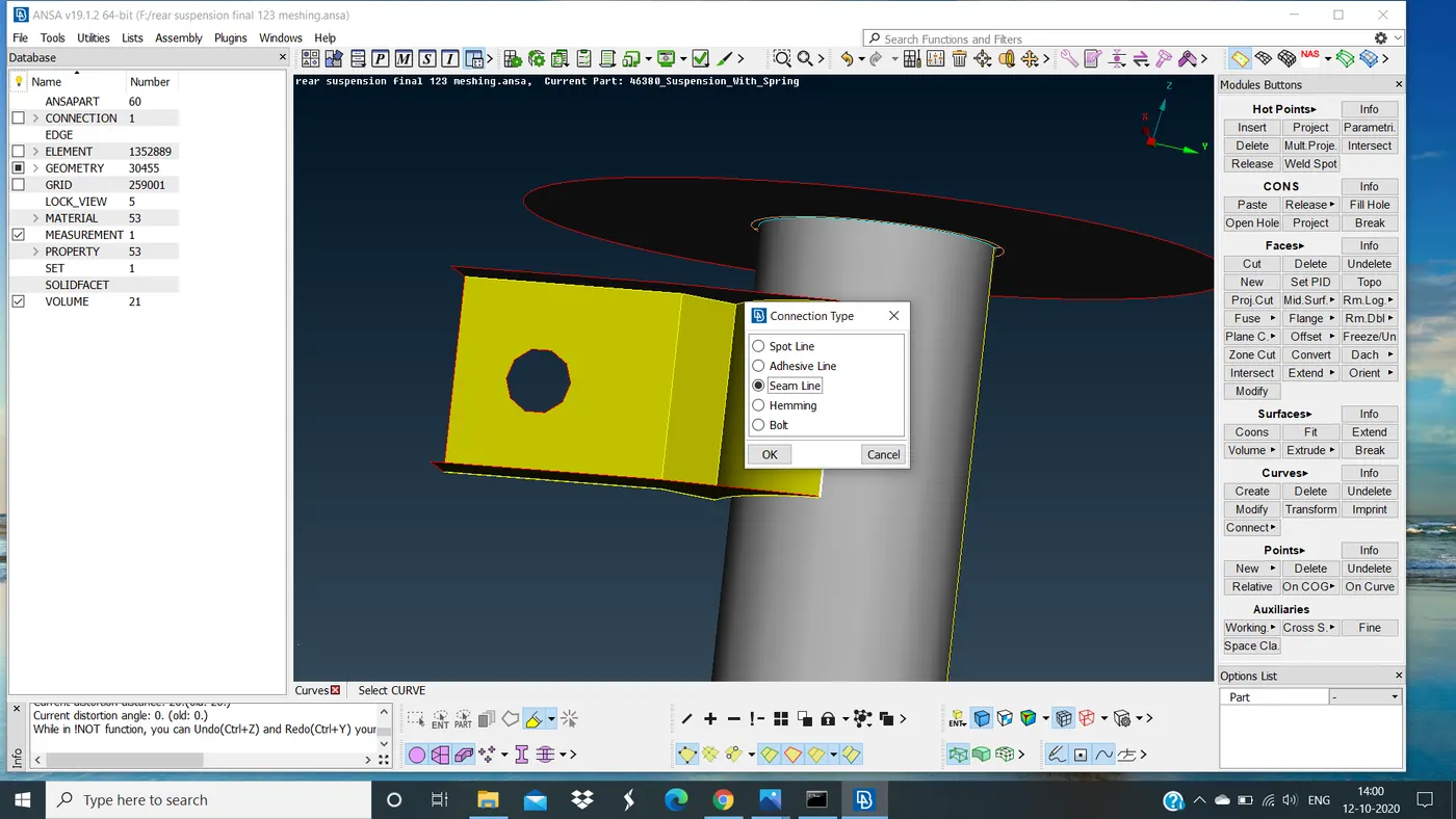
Convert curve to the seam line
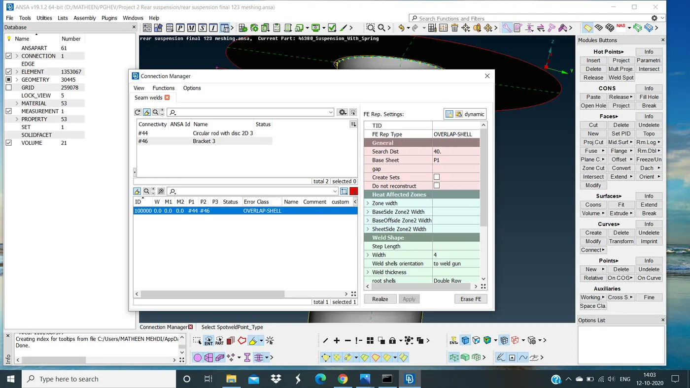
Selecting P1 and P2 value
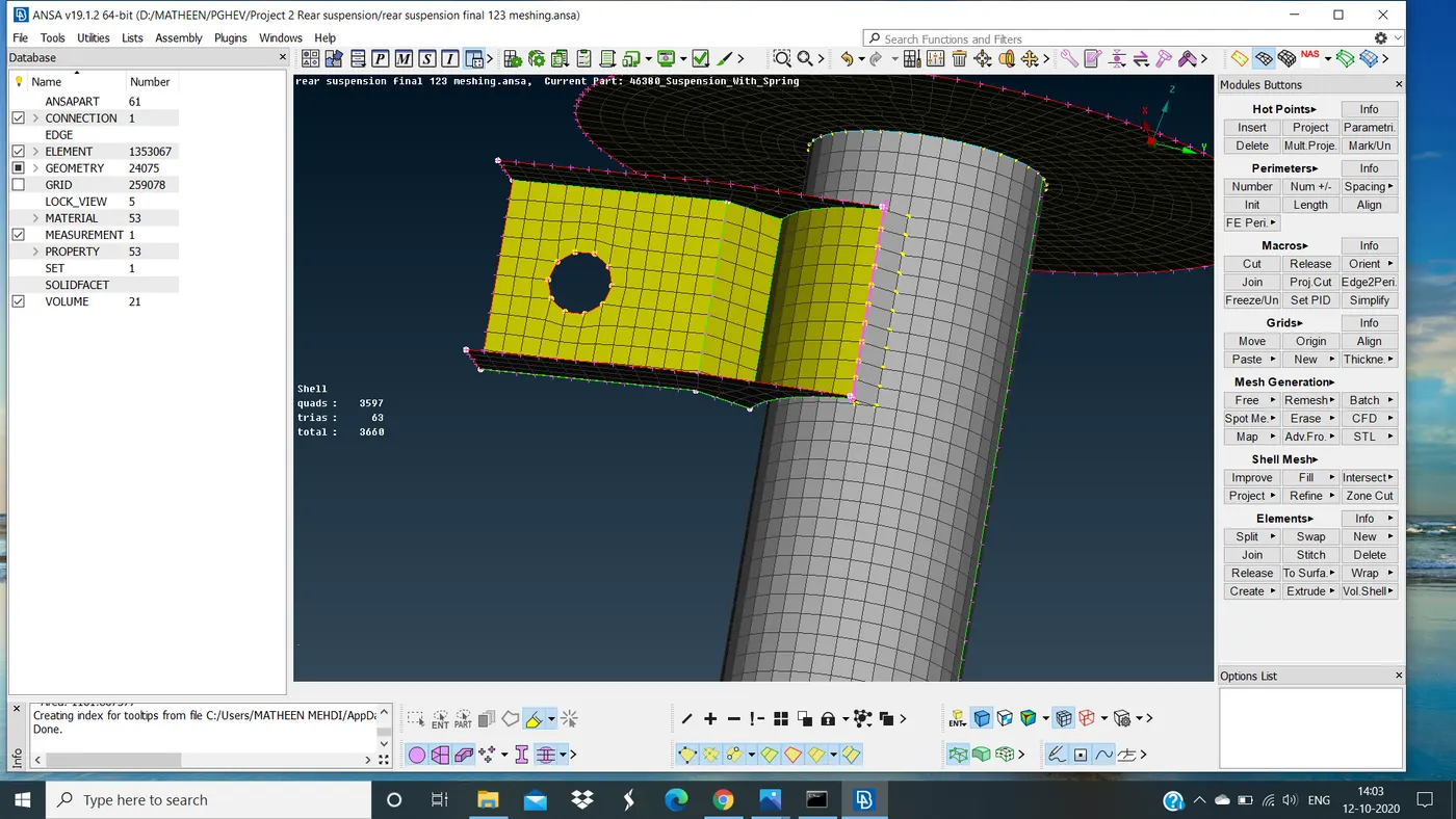
Seam weld is generated
PERFORMING SYMMETRY
The symmetry is done to make half the rear suspension to complete model we have to follow some steps.
In utility tab >> select transform >> copy >> select the entities >> select symmetry tab >> select mirror 3 points >> select 3 points which create a plane to get a proper symmetry >> click ok >> finish.
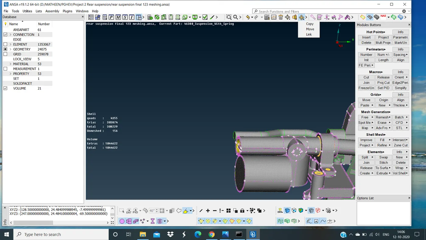
Transform selecting copy command
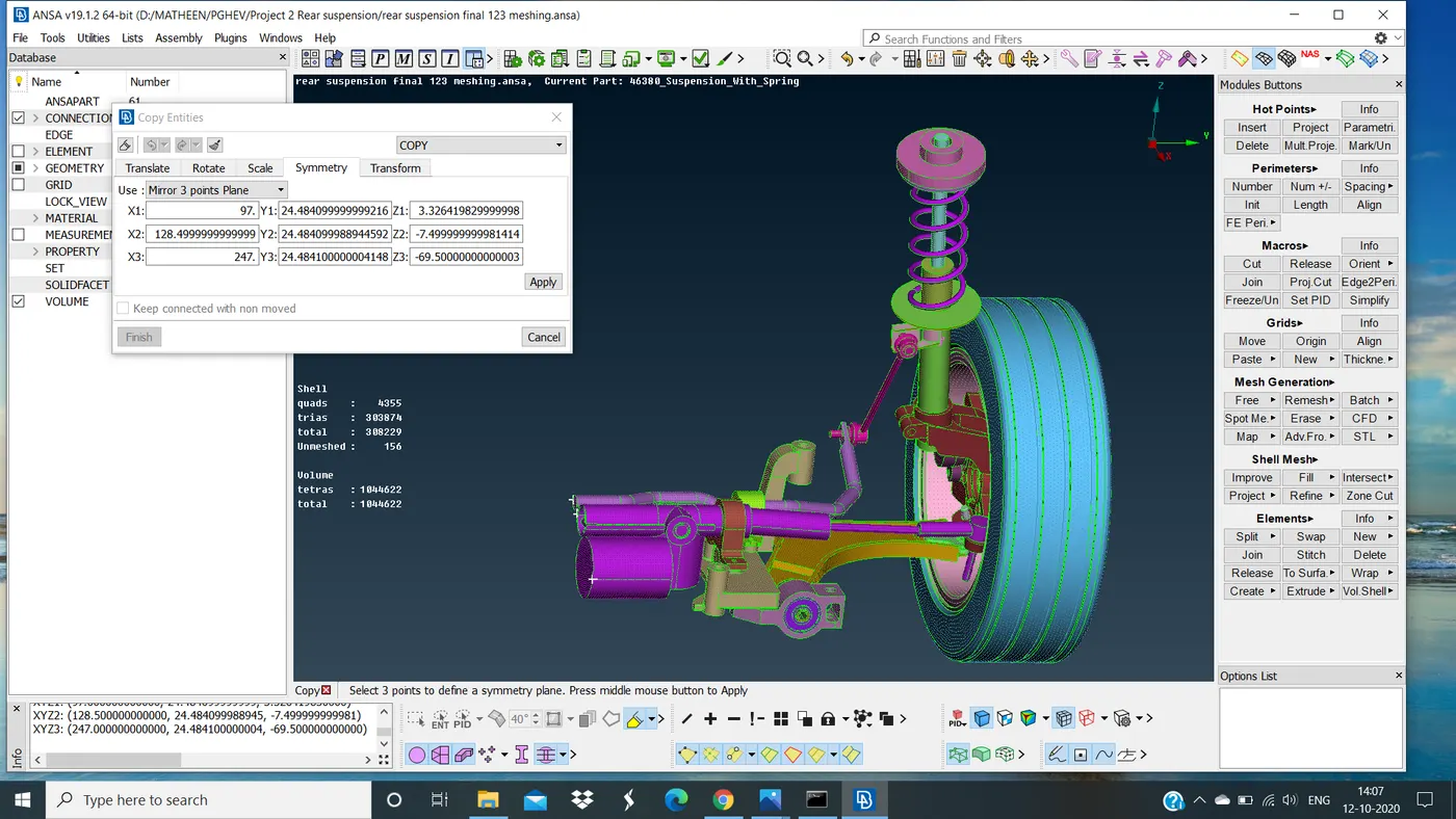
Symmetry by 3 points
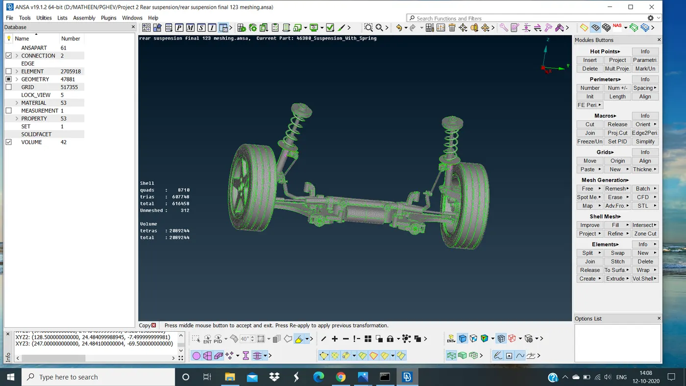
Final symmetry
RESULT :
All parts are successfully meshed as per the given quality criteria
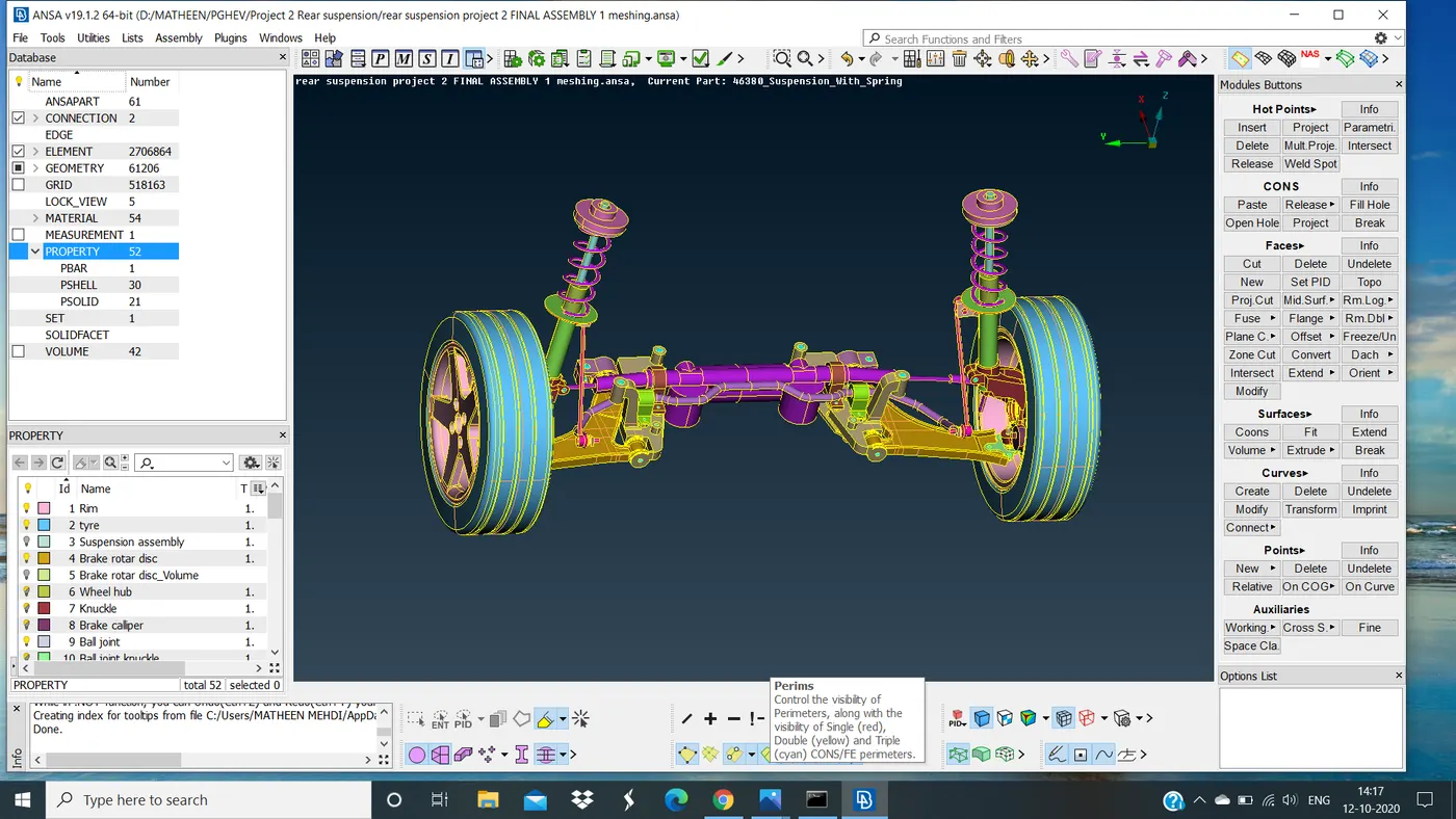
Final shell mesh geometry
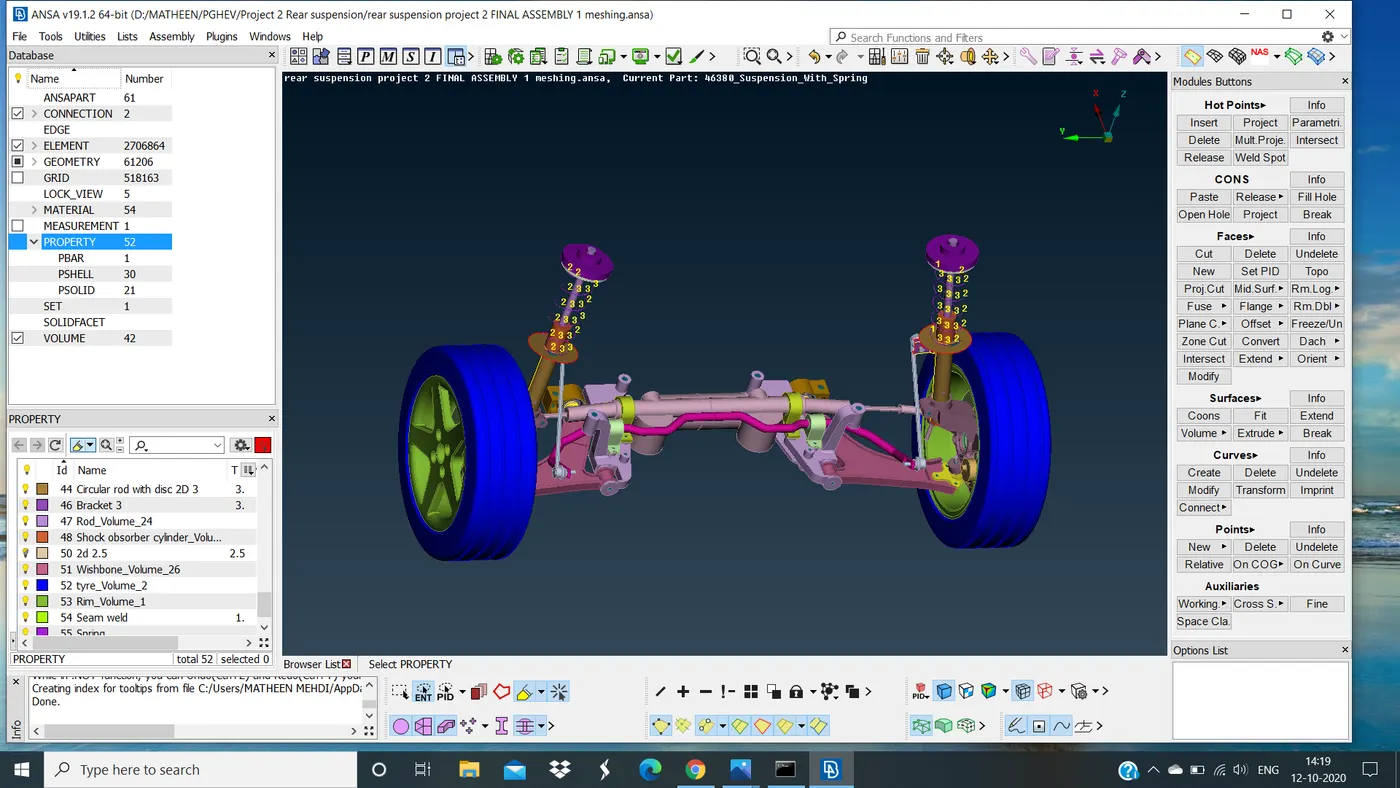
Final volume mesh
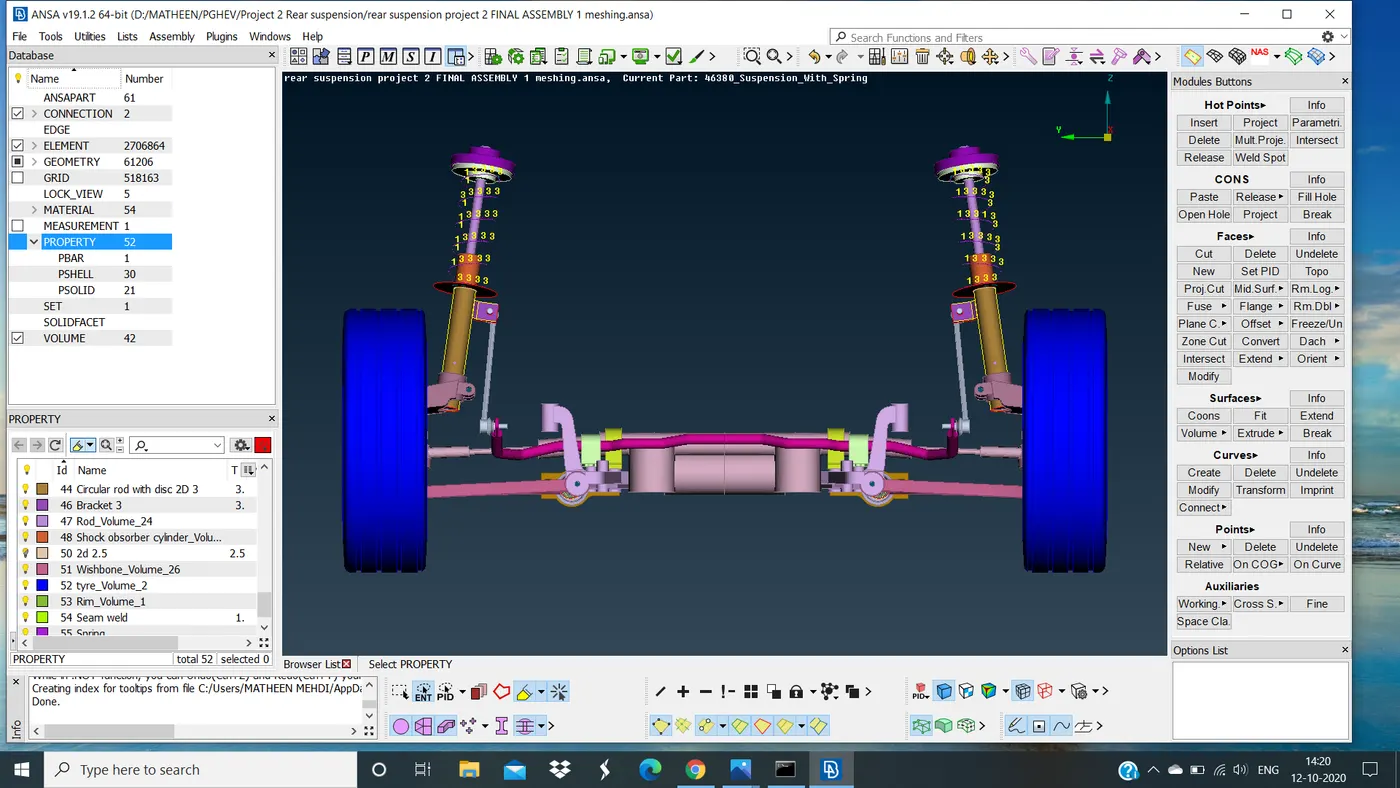
FRONT VIEW
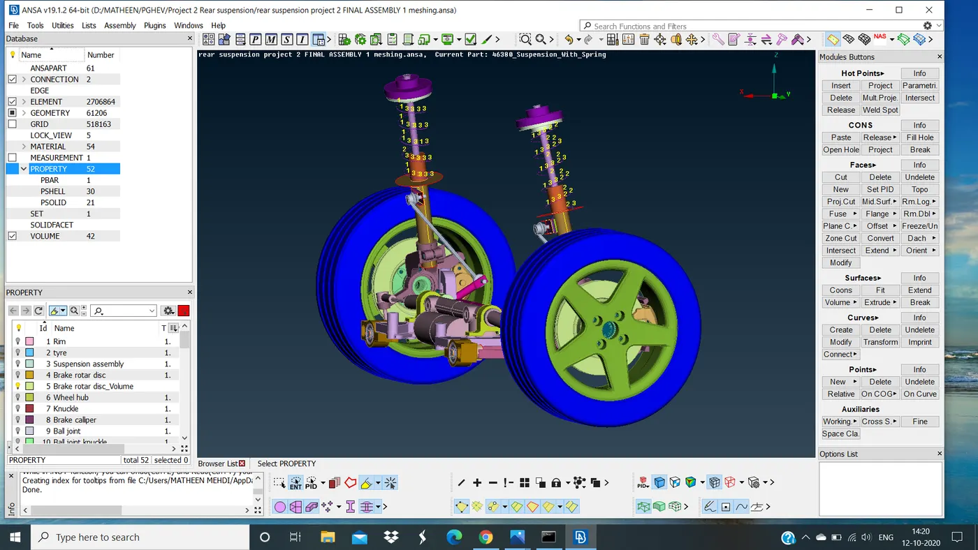
ISO VIEW
LEARNING OUTCOMES :
- Learned how to import CAD model into ANSA.
- Learned how to fix geometrical errors.
- Learned how to assign separate PIDs for each component.
- Learned how to create Auto mid by using the SKIN command.
- Learned how to mesh and good mesh flow with quality criteria.
- Learned how to make connections such as a bolt, seam weld, damping connection, etc..
- Learned how to make connections with RBE2 many nodes and RBE2 single nodes.
CONCLUSION :
In the above car rear suspension model successfully generate 2D shell, tetra meshing, and deploying the connections for the given model is done successfully by eliminating geometrical error's and considering the given element quality criteria using ANSA.