Project 2
In this project, we aim to route the wiring harness on a top opening Backdoor Class-A surface, and prepare flatten view and wiring harness drawing in CATIA V5. All types of packaging rules are considered while routing the harness. All necessary details like clearance, clips, harness continuity is considered while designing the wiring harness.
Backdoor connector requirements:
The Backdoor consists of One Interconnection Connector, One Stop Light connector, two brake light connectors, two Number plate light connectors, two defogger connectors and one wiper motor connector. The interconnection connector will connect the backdoor wiring harness to other parts of the vehicle and power supply. We will be using a 12-pole electrical connector as an interconnection connector.
Assumptions:
- Clips are provided as per requirement, to mitigate harness fouling while designing the wire harness. And provide enough tension to the harness bundles.
- When required, an additional slack of 5-10% is provided.
- Care is taken to avoid routing on sharp edges and are also provided with protective covering over the harness.
- Clearance distance of at least 150mm is maintained between main bundle segment routes.
- Branch length is greater than 50mm.
- Minimum distance between two branch points is at least 50mm.
- The wiring harness should be easy to assemble and easy to access.
- The bend ratio for all the bundle segments is assumed to be 1.4
Creating Context Assembly
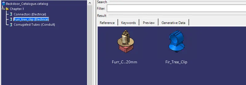
A Context Assembly will contain Backdoor Surface data and Wiring Harness Geometrical Bundle Assembly. The Geometrical Bundle will have the Multi-Branchable document with all the Connectors, Corrugated Tubes, and Furr-Tree Clips.
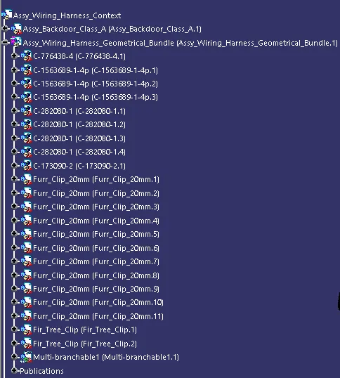
Defining Harness Components Electrically
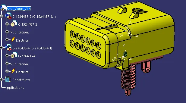
Connectors: All connectors, in the electrical part workbench
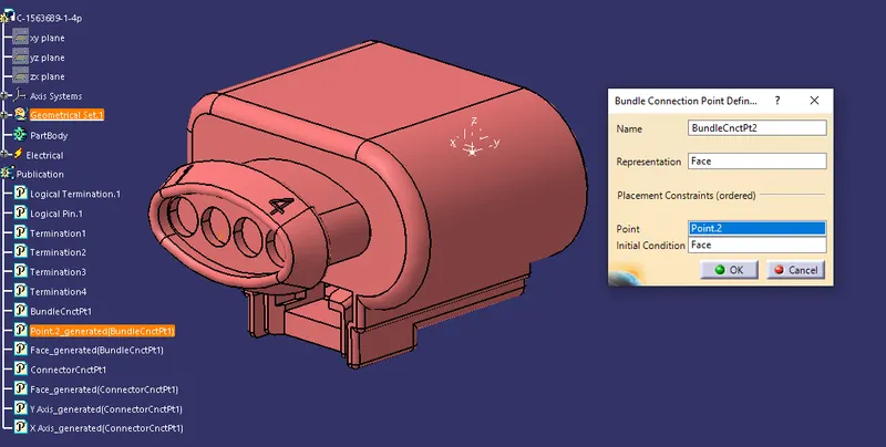
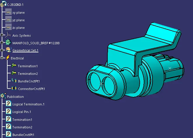
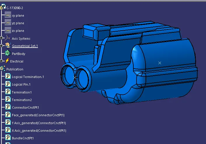
- Are defined as Connectors, by providing the number of pins available for connection.
- Bundle connection point is defined.
- Connector connection point is defined.
- For Interconnection Connector C-776438, Cavity connection point is also defined since mounting clip must be assembled.
Connector-1563689 - For Wiper Motor Connector and Brake light Connectors
Connector-282080-1 - For Number Plate Connectors and Defogger Connectors
Connector - 173090-2 - For Stop light Connector
Connector- 776438 - For Interconnection Connector
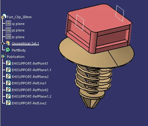
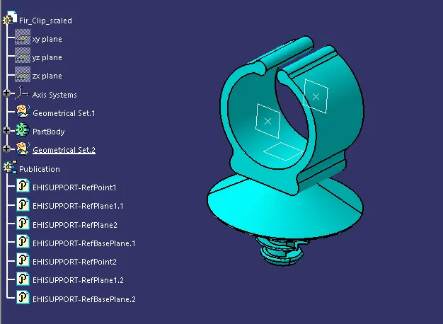
Clips: All Furr-Tree Clips
Are defined as support equipments and accordingly, bundle entry-exit planes and points are defined along with base plane as reference.
Importing Electrical Components to the Geometrical Bundle
A catalogue is created consisting of all parts required for the harness assembly and are imported to geometrical bundle from there.
Since Backdoor is a critical part and this is just a conceptual design, all connectors are placed in its respective position by using manipulation tools along with compass, snap, and smart move features.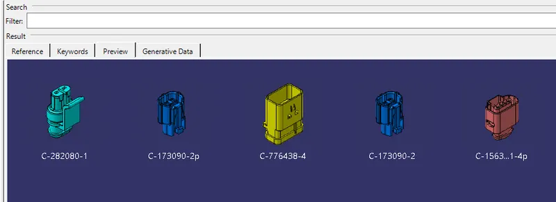
Electrical Harness Wiring
Branch Definition:
- The main electrical branch starts from Interconnection Connector. And is routed along the periphery of the Backdoor using Furr tree Clips which are screwed to the backdoor.
- The harness changes direction during routing from main branch towards brake light connector, here as well Furr-tree clips are utilised.
- Keeping a minimum distance of 55mm between branch points, convenient points are added on to the main harness branch to route the harness over all connectors.
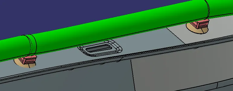
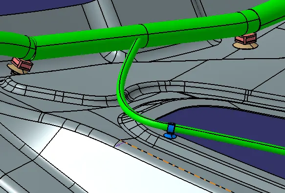
Adding protective coverings to harness bundle
To provide protection for wiring harness, corrugated tubes are utilised as coverings. For 15mm bundle segment 20mm Cot tubes, for 10mm bundle segments 15mm cot tubes, for 5mm bundle segments 10mm Cot tubes are utilised.
A minimum clearance of 30mm is provided for Corrugated Tubes near each connector-bundle entry point.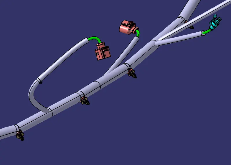
Checking bundle continuity
Go to Edit>Search>Workbench-Electrical>Type-Bundle segment>Attribute-fully connected.
A pop-up window will open, in that selecting True option will show all the connected bundle segments while selecting False option will show all the non-connected bundle segments.
In the false option, there are Zero bundle segments. Hence all bundle segments are connected.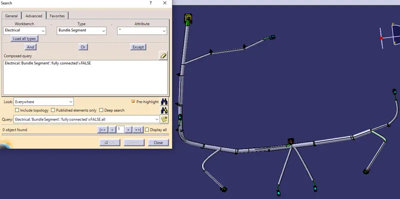
Wiring Harness Flattening
Defining Harness Flattening parameters
- A new Product file is created inside the Electrical Harness Flattening workbench.
- Next, we should define the harness flattening parameters by clicking on its respective icon. And necessary settings are changed.
- It is recommended to have single line representation for bundle segment and double line representation for protective coverings, for easy differentiation.
Flattening of the Harness
- To flatten the harness, the flattening plane must be selected by selecting a reference face from any connector and all the harness branches present in the assembly.
Once it is flattened, by using rotate command, the bundle segments can be rotated, bent as per our requirement for easy arrangement on the drawing sheet.

Creating 2-D drawing of the Wiring Harness
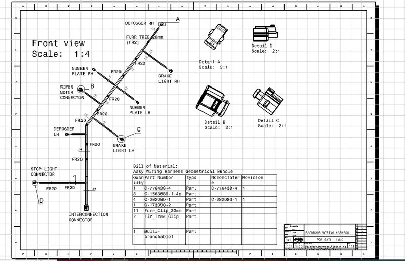
We should insert the front view of the wiring harness into the drawing file as shown below.
In the view tab of properties pop up window of the front view, 3D wireframe should be always "visible". If this setting is not selected the bundle segments will not be visible in the drawing view.
Drawing Sheet Features
- A typical/simple Wiring Harness Flattening drawing must have
- Front view of the Wiring Harness Assembly
- Frame and Title block
- Detailed view/Scale view of connectors
- Bill of materials
Conclusion:
In this way, we have routed wiring harness for a Class-A surface of Backdoor. Also, prepared flattened view drawing for the same.