Project 2
Route the Wiring harness on Given car body and Prepare flatten view drawing in CATIA V5. Application of all Packaging rules, Industry best practices studied in this course shall be demonstrated in design. Apply Protection coverings as required.
Prepare & Submit all necessary reports like clearance, Clipping/Clamping selection, Harness fixing requirements, Harness continuity, Assumptions if any along with CATIA 3D data.
-----------------------------------------------------------------------------------------------------------------------------------------------------------------------
Clearance-
Sufficient clearance is provided to avoid foweling of harness with any surrounding component.
Clipping/Clamping selection-
Firr Tree clip and Pclamps are selected for routing
Harness fixing requirements-
Harness creation started from an Ingterconnection Connector, which get connected to automobile harness.
As per Backdoor Requirement following electrical connections are required-
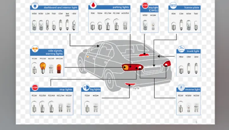
2 side lights, 2 parking light, 2 stop signal, 2 reverse lights for LH and RH assembly. For these a 8 port connector selected for each side.
1 connectors for License plate., 2 port
2 connector for Fog Light. 2 pole
1 Wiper motor connector. 2 pole
2 Pole connectors 4 NO.
8 pole connectors 2 No,
All connectors and clips are electrically defined.
and added to Geometrical Bundle product.
Typical Parts to be connected in a backdoor.
Harness continuity-
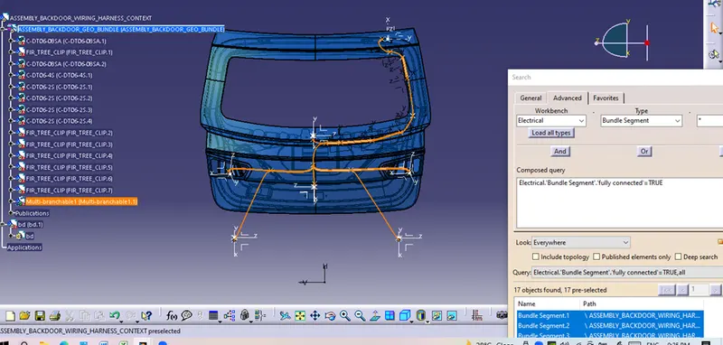
After completing complete harness routing, it si checked for continuity. All connections are proper and true.
flattening Assembly-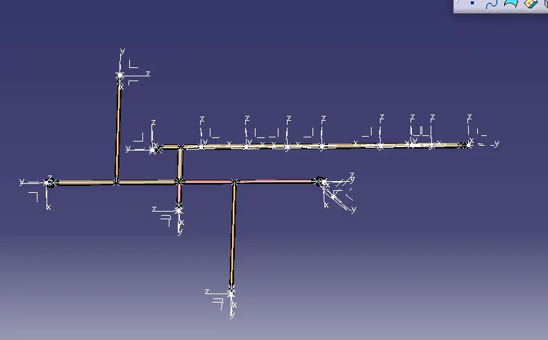
Assumptions if any along with CATIA 3D data.
1. As only class A surface of the backdoor is provided as input, sufficient space is not available to mount L-clamps and p Clapmps.
few Firr Tree clamps are used and it is requested to creates holes for the required clips.
(After finalizing the routing, respective hole can be created for th efirr tree clamps.)
2. For Automobile harness to Connector Connection connector, a slot is to be creatd in the flanges of backdoor. At upper left corner of door.
3. All connectors are assumed to be placed on respective mountings.
All connectors are IP 67 rating. It will protect connectors from Dust and water.
Assembly is started with Mechanical Assembly workbench-
Dffernt connectors are arranged to resprctive locations for Back lights, Fog Lights, and License Plate.
Cot tubes are provided for protection.
following Workbeches are used-
Mechanical Assembly- for fixing ideal location of components.
Electrical Part WB- for defining parts as electrical part.
Electrical Harness Assembly- for creating routing
Electrical Flattening Assembly- For Flattening routing
Drawing- to create 2d representation 0f the flatten assembly.