Week 8 - Challenge 1 - Base Bracket Design
Report:
Creating Tooling Axis:
Tooling Axis is the direction in which mold opens, ie while production, cavity and core get separated along parting line. The direction of MOvement of core is the tooling axis.
Tooling direction could be in any direction, X, Y and Z accordig to component geometry.
out of three, best possible can be selected.
If there are holes, it should considered as tooling direction.
While deciding Tooling Direction, maximum geometry should clear in the direction.
it should be simple and accurate.
Steps To create a tooling direction for given component:
Checked boundary, it should be a contionuous boundary, it was a continuous close and single boundary.
Create Co-ordunate system. (not current), at centre point of big hole.
Line to present Tooling Axis (temporary).
Surface perpendicular to TA, zero angle and postive angled faces are not creating any problem.
still for cross checking, one shoul exratct faces, and check whther they if extended, do intersect TA.
for this bisecting Method is used.
BIsecting Mecthod:
Bisecting line will actually bisects the angle of Sufraces with Z (or Temporary Idea Direction)and creates a line.
Create the approximate or Temporary TA by observation.
See walls of component, Intersection of component along remaining Two planes. Creating Tooling Axis along those Axes accordingly.
Tooing axis -x Direction and TA -Y direction are now ready.
Bisection these two Direction Axes will gove final Tooling axis.
IN given component,
I do not use bisecting method,
1. a large flat surface and 2. a hole is there to th component which can directly selected as tooling axis.
3. along x axis part is simple
4. along y axis part need to conseder for tooling clearing.
tooiling clearing along yz direction is to be checked.
becasue there are 4 walls with draft parallel to tooling axis.
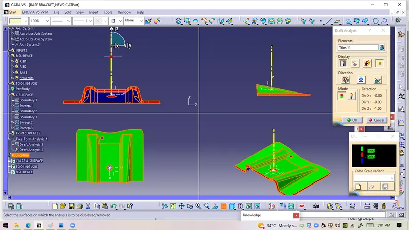
Draft Analysis;
Draft is small taper provided for plastic components to assure its easy removal from the mold after cooling, as result of Clinging to core once it shrinks after cooling.
In general Draft is provide along direction of mold movament.
min 1/2 to 1 degree and upto 3 degree draft is accpeted for plastic parts.
for ribs, screw bosses a minmum draft is required.
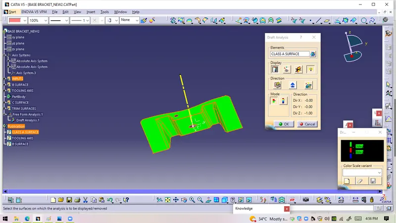
Draft Analysis is performed as follow:
First A tooling Axix is created.
Insert - Analysis-Feature Draft ANalysis.
Using Compass to define draft direction.
on placing compass to TA, it will show value of all drafts for every surface.
once it gets placed, we can get draft values for each face Running POint ANlysis.
It will show it will exact value of draft and as per Range set, accordingly.
In general 0 to 3 degree draft is allowable for plac=stic parts, we can get an idea about draft provided are acceptable or not. If all faces are represnting Green Color , it means it it ready to design.