Week 9 - Attachment Feature Creation (Ribs & Screw Boss) - Challenge 1
REPORT:
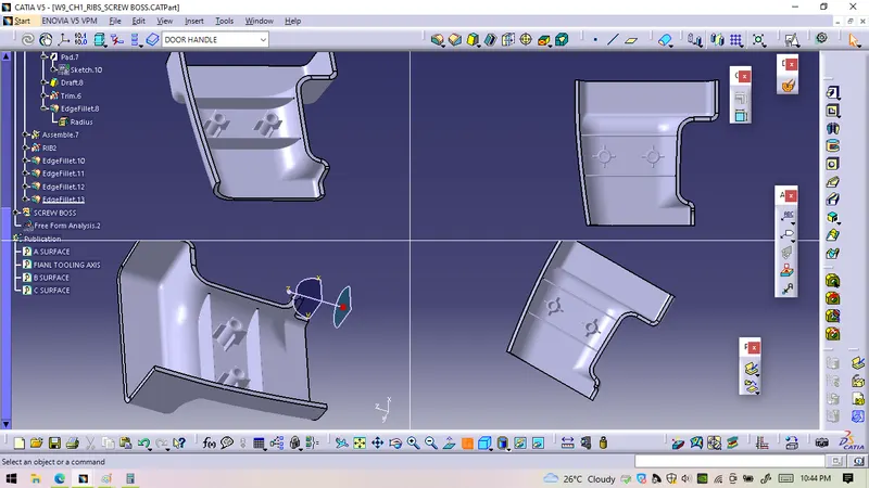
Part files are provided for Door Hnadle, in question, asked for Create the rib for the Drill Handle considering the design rules mentioned in the video.
(Designing features for Door Handle assuming a thickness of 2.5 mm.)
1. separate Geom. Set Created for Class A surface. Checked for boundary. there is single , continuousus boundary.
2. Tooling Axis Creation:- as part has flat bottom surface, a line normal to this surafce can be cosidered as TA.
will chwck for bisecting method too.
as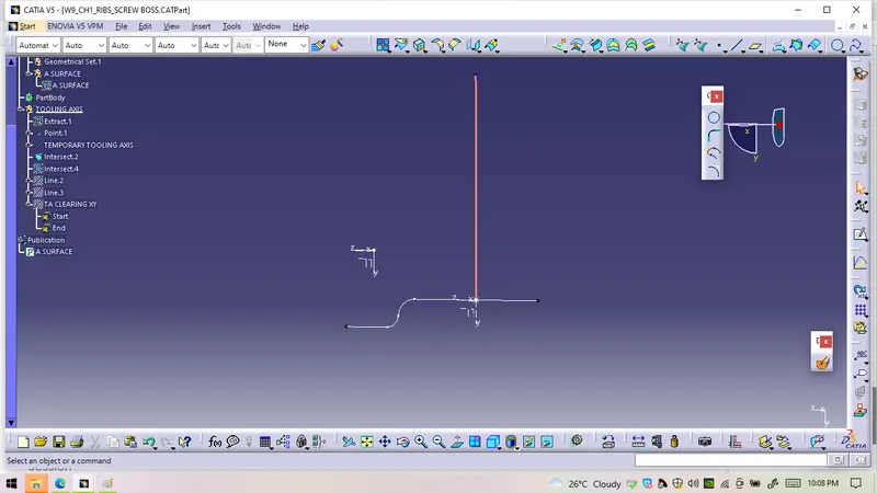
As lines are perpendicular to temp. tooling axis,will not create a problem. in yz plane
hence the normal line to surface, can be used as Tooling axis for clearing in y direction. (Temporary Tooling Axis)
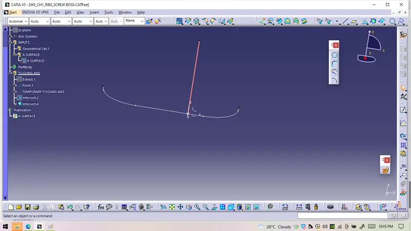
In this intersction, two lines will draw, at extreme ends, as they are at an angle to TA.
by bisecting these two, axis in z direction clearing will obtained. (Tooling Axis in x direction)
Bisecting these two lines will give final tooling axis for the part.
Draft Analysis:
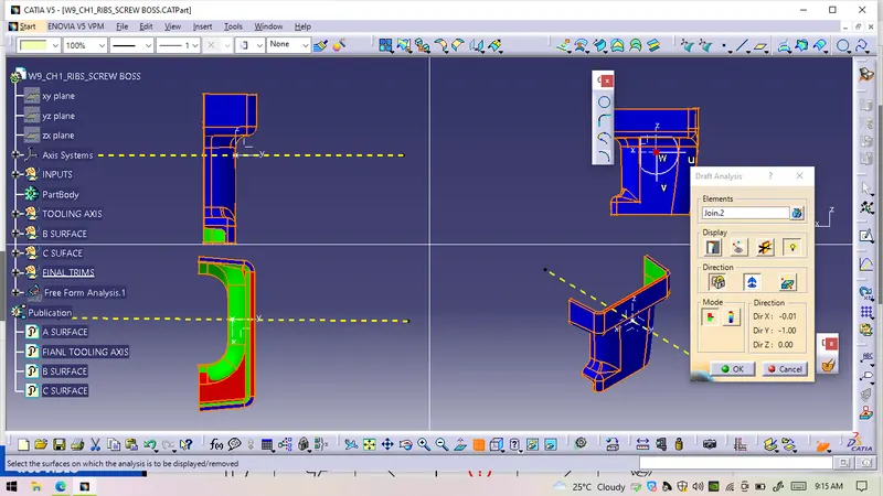
initially for class A, and final draft analysi on closed body is performed.
some faces are at 0 degree draft.
rest maximiu are within acceptable limits.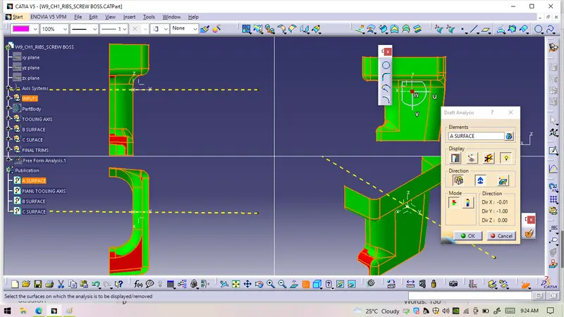
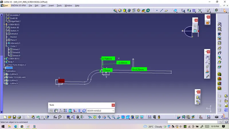
Dimensions for Rib, calculations , thickness of component =t=2.5 mm
Draft-.5 deg
Thickness= 0.4*t= 0.4*2.5 = 1 mm
Height of rib= < 5*2.5 = < 12.5, we take it 12 mm.
Spacing- = 2*t= minimum 2*2.5 = 5 mm.
as per need of design spacing is much more than minimum.
Thickness at top = 0.75 mm.
Fillet= 0.25 mm
Root Diameter= 30% of t = 2.5*1.3 = 3.25 mm,
at our design, root diameter is