Week 8 - Challenge 3 - Coin Holder Design
Report:
Creating Tooling Axis:
Steps To create a tooling direction for a component:
- checked the boundary, it was a single contionuous boundary.
- as one of the faces was at 0 degree, i.e. it has no draft angle.
- an intersection of YZ plane with part, and a point at centre of base surface finalized as tooling axis.
- zalong Z direction.
In general, tooling axis is tried for three possible directions, as x, y n z as per part requirement.
bisecting method is used to find an most accurate axis using for either two directions.
e.x. current part was clear in x direction as it was symmentrical.
and in yz direction, its tooling clearing needed to check.
being a flat surface at base, and a zero draft angle for one of the surfaces, we can directly use Z direction at centre of base. as tooling axis.
I did not follow the bisecting method for this part.
Draft Analysis;
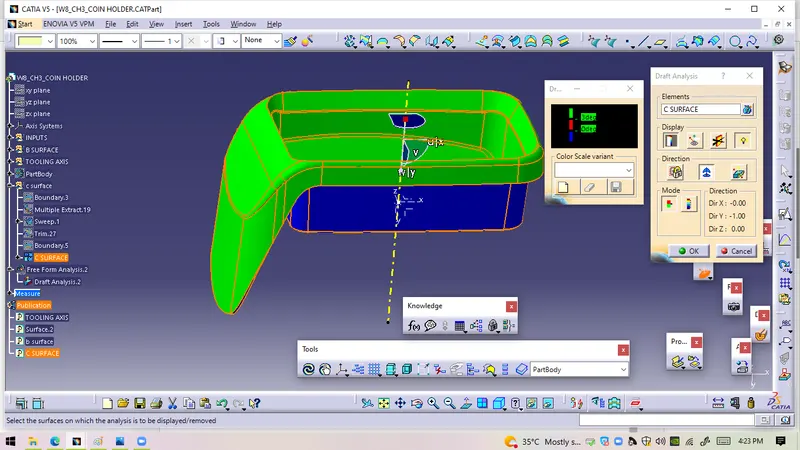
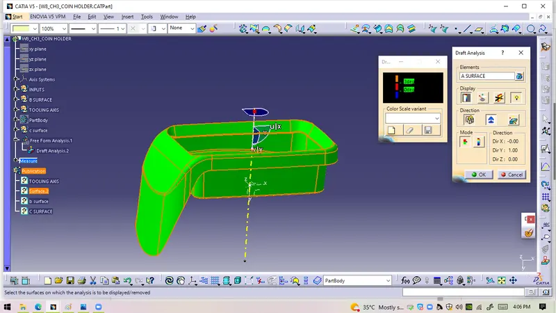
along tooling axis, draft analysis compass is aligned, and every surface is cheked (compared with the standard 0 to 3 degree)
For class A surface initially DA done.
The part was within acceptabke limits and hence ready to design.
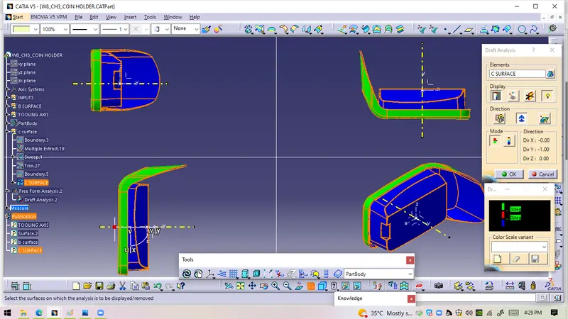
After Finishing close surface, second DA is performed.
at final time, also drafts are within limit.