Project 1 - Controlling a DC motor using PWM and monitoring its Running status
Implement a system on the simulator for controlling a DC motor using L293 motor driver, monitor its status and print the running status of motor on the LCD Display.
AIM:
To Implement a system on the simulator for controlling a DC motor using L293 motor driver, monitor its status and print the running status of motor on the LCD Display.
PROGRAM PROCEDURE:
- In Microchip studio IDE we are creating a new project with ATmega 32 micro controller as a device.
- The required header files like <avr/io.h>, "avr/interrupt.h" and <util/delay.h> is declared and the CPU frequency is also defined.
- Using macros we are defining the PORTC as lcdport and also making D6, D5 pins as register select and enable pins respectively.
- Using macros we are declaring the power_button, direction and speed button.
- Also we are declaring an unsigned character variable named as "var".
- In main function we are making PORT C pins as output using DDRB since these pins will be connected to LCD data pins.
- Using DDR register we are making port B, port A pin 0, pin 1, port D pin 5, pin 6 as output pins and port D pin 1, pin 4 as input pins.
- Using PORT register we are enabling the pull up resistor for port D pin 1, pin 3 and pin 4.
- We are declaring the global interrupt function sei() and setting bit 7 of the GICR register as high in order to select the INT1 interrupt.
- We are intializing the variable "var" as 64 since 25% of duty cycle is applied to the motor.
- We are providing the value for the register TCCR0 as 0x64 since this will select the phase correct PWM, Clear OC0 on compare match when up-counting and Set OC0 on compare match when downcounting. No prescaler values.
- We are providing the value for the register MCUCR as 0x80 in order to select the falling edge of INT1 generates an interrupt request.
- We are calling the function named as lcd_init() inside the main function.
- Using infinite while loop we are checking the status of the power button is pressed or no using another while loop.
- If the power button is pressed then we are using if else condition to check the status of direction button.
- In if condition we are checking the direction button is pressed or not, if it is pressed then providing the value of 0x01 to L293 driver so that it will make the motor to rotate in clockwise direction.
- Also using the lcd_out function we are displaying that the "Motor running in Clockwise" direction.
- Suppose the if condition fails then we are providing th value of 0x02 to L293 driver so that it will make the motor to rotate in Anti-clockwise direction and using lcd_out function we are displaying that the "Motor running in Anti-clockwise direction.
- We are storing the value of var to the OCR0 register(Output compare register). Outside the while loop we are providing the 0x00 value for PORTA pins 0 and 1 in order to stop the motor.
- Using the lcd_out function we are displaying that the "Motor is OFF".
- We are defining the Interrupt subroutine ISR(INT1_vect) and incrementing the value of var by 25 outside the main function.
- In function definition of lcd_init() we are calling 6 commands to set the LCD using the lcd_cmd() function.
- In function definition of lcd_cmd() we are storing the commands in the lcdport variable, making rs_low, enable high and after a delay of 1ms making enable low. This set of codes helps in setting the commands to the LCD display.
- In function definition of lcd_data we are storing the data in the lcdport variable, making rs_high, enable high and after a delay of 1ms making enable low. This set of codes helps in displaying the messages in the LCD display.
- In function definition of cursor_pos() we are checking the entered row value is not less than 1 and greater than 2, similarly the column value is also checked.
- In lcd_out function definition we are using CHAR * in order to get the string and display it in the LCD display.
SIMULATION PROCEDURE:
The below components are required for the simulation:
- ATMEGA32
- LCD DISPLAY
- L293 DRIVER
- DC MOTOR
- PUSH BUTTON
- SWITCH
- FIXED VOLTAGE SOURCE
- GROUND
- RESISTOR
- The power button, direction and speed buttons are connected to the Pin D4, D1 and D3 of ATMEGA32.
- The another end of power button, speed button are connected to ground whereas the another end of direction button is connected to fixed voltage source and also connected to ground via 10K resistor.
- The PORT C pins of ATMEGA32 is connected to LCD display, the RS pin and enable pin of LCD is connected to D6 and D5 respectively.
- The pin PB3 is connected to enable pin of L293 driver, the PORT A pins A0, A1 is connected to L293 driver pins 1A and 2A respectively.
- The DC motor is connected to the 1Y and 2Y pins of L293 driver.
CODE:
/*
* AVR_PROJECT_1.c
*
* Created: 15-10-2022 10.01.56 AM
* Author : Jagadesh R
*/
#include <avr/io.h>
#define F_CPU 16000000L
#include <util/delay.h>
#include "avr/interrupt.h"
#define lcdport PORTC //PORTC AS LCD, MACRO
#define rs_high() PORTD |= (1<<6); //D6 logical high
#define rs_low() PORTD &= ~(1<<6); //D6 logical low
#define en_high() PORTD |= (1<<5); //D5 logical high
#define en_low() PORTD &= ~(1<<5); //D5 logical low
#define direction (PIND & (1<<1))
#define power_button (PIND & (1<<4))
#define speed (PIND & (1<<2))
unsigned char var;
void lcd_cmd (unsigned char cmd)
{
lcdport=cmd;
rs_low(); //command register selected
en_high();
_delay_ms(1);
en_low();
}
void lcd_data (unsigned char data)
{
lcdport=data;
rs_high(); //data register selected
en_high();
_delay_ms(1);
en_low();
}
void lcd_init()
{
lcd_cmd(0x38); //5*7 matrix
_delay_ms(5);
lcd_cmd(0x02); //return home
_delay_ms(5);
lcd_cmd(0x01);//clear screen
_delay_ms(5);
lcd_cmd(0x0c);
_delay_ms(5);
lcd_cmd(0x06);
_delay_ms(5);
lcd_cmd(0x80);//first line
_delay_ms(5);
}
void cursor_pos(char x, char y)//x-row,y-col
{
if((x<1||x>2)||(y<1||y>16))//any typo mistakes
{
x=1;
y=1;
}
if (x==1) //0x80 -1,1 1,2-0x81 1,3-0x82.....
{
lcd_cmd(0x7F+y);//7F+2
}
else //0xC0
{
lcd_cmd(0xBF+y);//BF+5=C4
}
}
void lcd_out(char x, char y, char *str)
{
cursor_pos(x,y);//2,5
while(*str)
{
lcd_data(*str);
str++;
}
}
int main(void)
{
/* Replace with your application code */
DDRC = 0xFF;
DDRB = 0xFF;
PORTB = 0xFF;
DDRA |= (1<<0) | (1<<1);
DDRD &=~ (1<<4);
DDRD &=~ (1<<1);
DDRD |= (1<<5)|(1<<6);
PORTD |= (1<<1);// to enable pull up for direction button
PORTD |= (1<<4);// to enable pull up for power button
PORTD |= (1<<3); // to enable pull up for interrupt
sei();
GICR |= (1<<7);
var = 64;
TCCR0 = 0x64;
MCUCR = 0x80;
lcd_init(); //6 commands for lcd initialisation
while(1)
{
while(power_button == 0)
{
if(direction == 0)
{
PORTA = 0x01;
lcd_out(1,1,"Motor running");
_delay_ms(5);
lcd_out(2,1,"in Clockwise");
}
else
{
PORTA = 0x02;
lcd_out(1,1,"Motor running in");
_delay_ms(5);
lcd_out(2,1,"Anti-clockwise");
}
OCR0 = var;
}
PORTA = 0x00;
lcd_out(1,1,"Motor is OFF");
}
}
ISR(INT1_vect)
{
var = var + 25;
}
SIMULATION OUTPUTS:
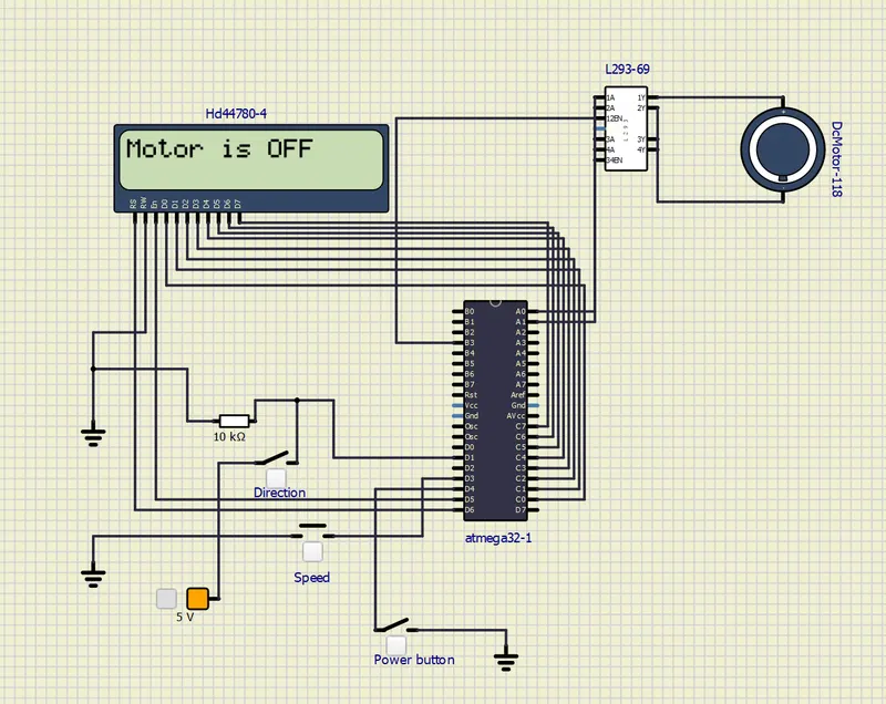
In the above snap the power button is open so the LCD display shows the "Motor is OFF"
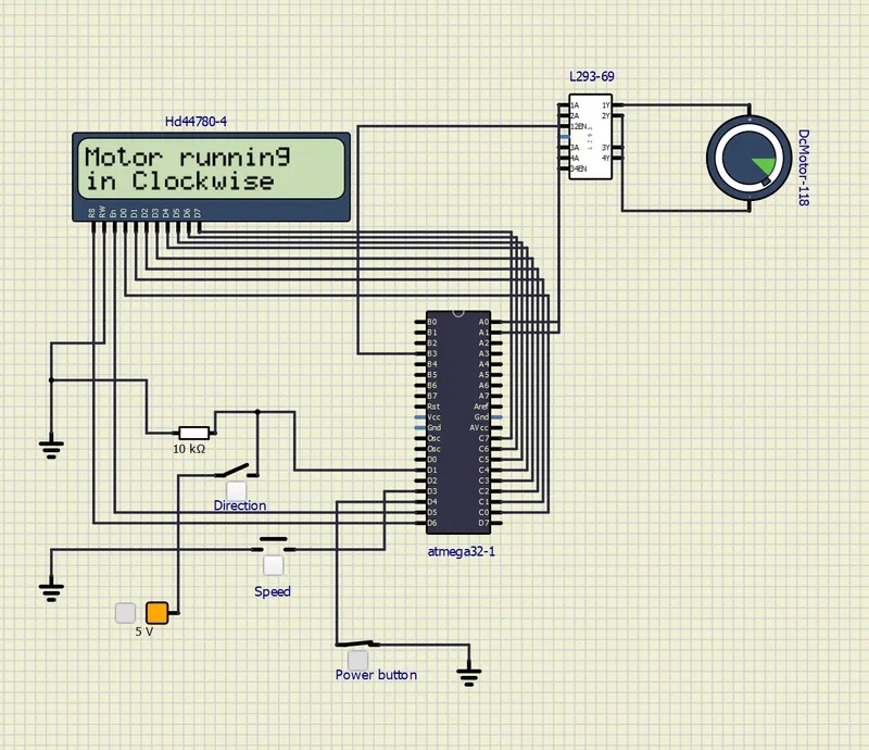
In the above snap the power button is closed and direction button is open so the LCD display shows the "Motor running in clockwise"
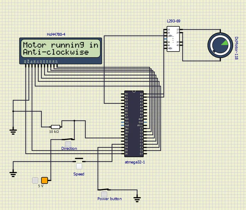
In the above snap the power button is closed and direction button is closed so the LCD display shows the "Motor running in Anti-clockwise"
RESULT:
Thus a system is implemented on the simulator for controlling a DC motor using L293 motor driver, monitored the status and printed the running status of motor on the LCD Display.