Project 1
1a)
AIM : To Model a Ceiling from architecture tab above the walls at first floor level
TOOL/COMMANDS REQUIRED :
File
Architecture
Ceiling
Sketch ceiling
Ceiling plan view
PROCEDURE :
- we have to browse the saved file from the saved project.
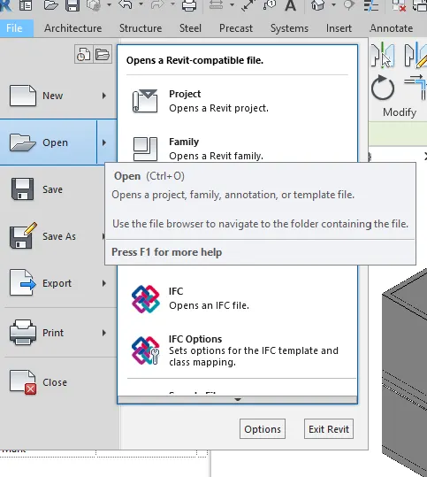
- In that we already have a first floor and second floor along with the floor respectively.
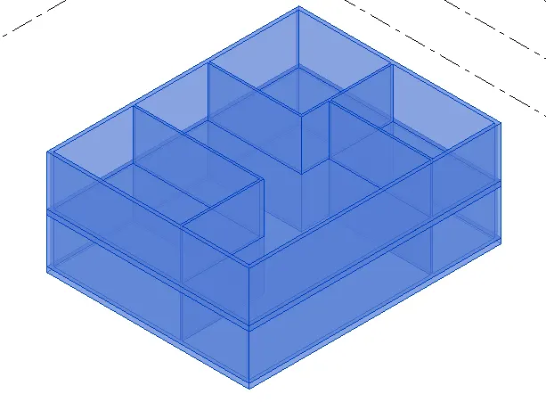
- select the view option in the tools bar and select the elevation view to dee more clearly
- Select the architecture tool from the tools bar.
- Select the ceiling option from that drop down menu.
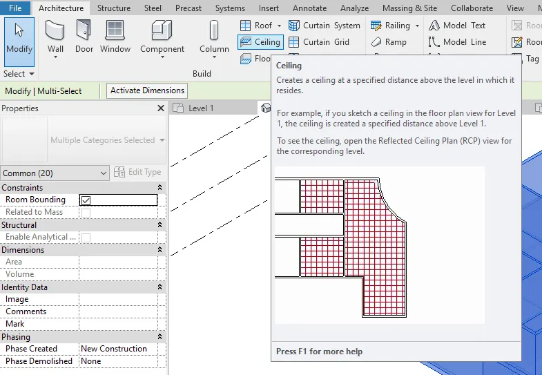
- Now to add the ceiling to the ground floor we have to select the ground floor level.
- Now after selection of the level where we have to add the ceiling we have to select the skecth ceiling in the modify tab.
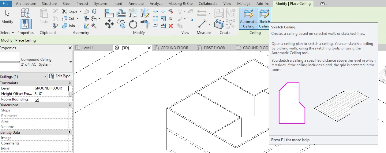
- Now we have to select the outer lines of the wall and atlast after selecting a closed loop we have to select the tick mark which we find on the top of the menu bar.

- Ceiling for the ground floor at first floor level is been created.
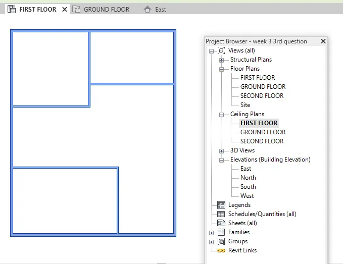
RESULT :
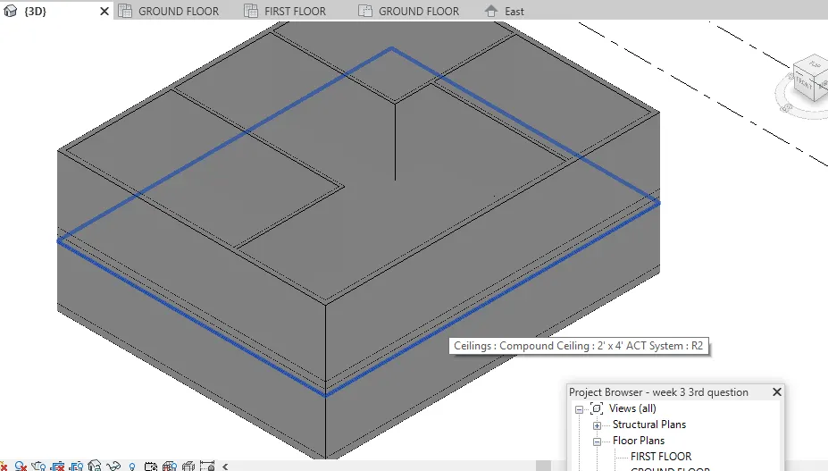
The required ceiling for the ground is done clearly.
2a)
AIM : To Model a roof above the ceiling by selecting the footprints of ceiling.
TOOL/COMMANDS REQUIRED :
File
View
Architecture tool
Roof
Properties
PROCEDURE :
- We should open the file which is already saved with ceiling attached to the layout.
- Now to add the roof element to the project we have to select the architecture tool.
- We have to select the Roof option in that.
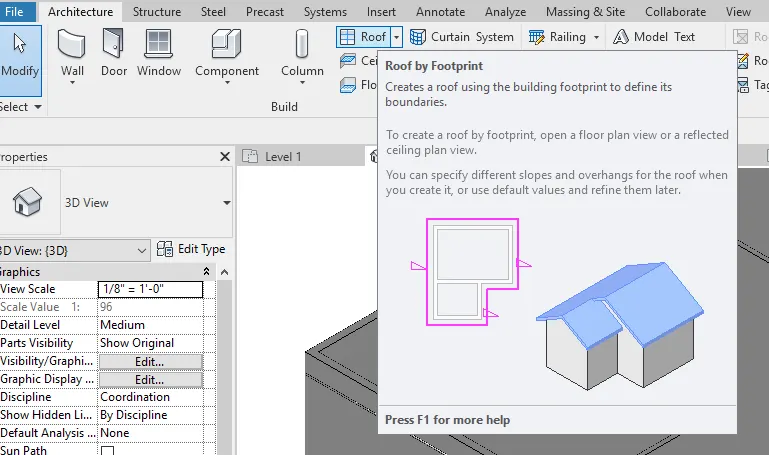
- Now after selecting roof we have to select the level at which we want to add roof.
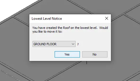
- Now we have to select the pick lines option to select the outer lines of the ceiling to add the roof.

- Now at last we have to select the finish edit mode option.

- Now to adjust the degrees of the roof we have to select the roof.
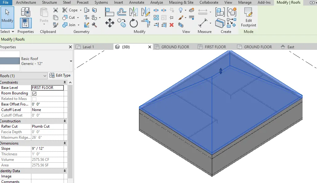
- And now we have a slope option in the properties.
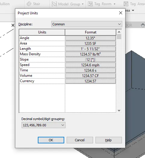
- if we dont have the units of our requirement then we have to change our units in the units menu to our required dimensions.
- Now select the slope option in the properties menu and there we have to change it to 10 degrees.
RESULT :
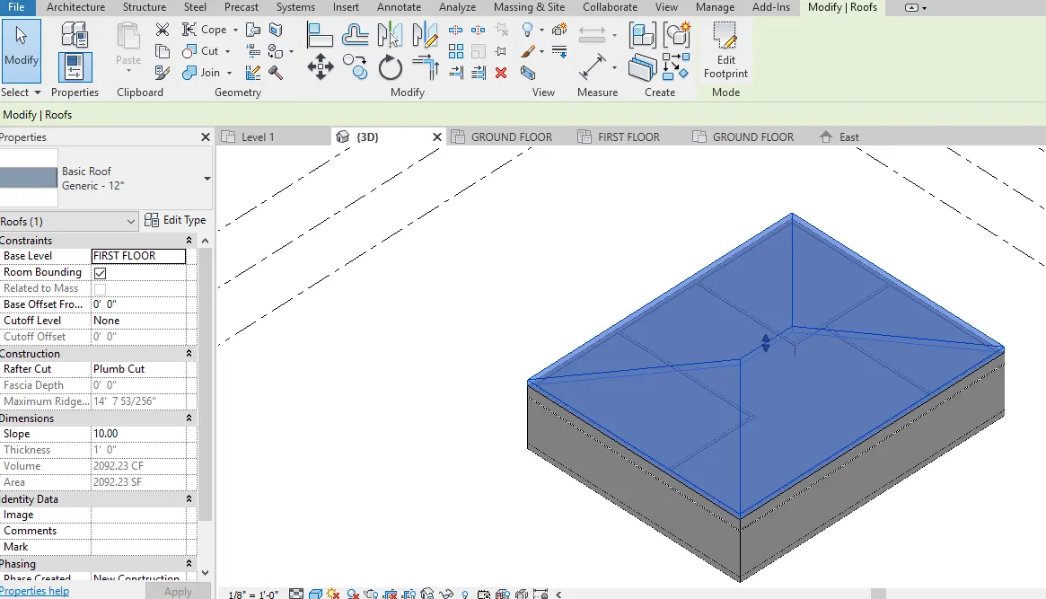
The required roof along with the degrees required hs been created.
3a)
AIM : To create plan views for ground floor level and first floor level.
TOOL/COMMANDS REQUIRED :
Open
View
Plan views
Level
PROCEDURE :
- Now to that file to create the plan views we have to select the view option in the toolbar.

- And in that we have to select the plan views option to create the plan views.

- After selecting the plan views option we have to select floor plan option in that.
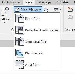
- Now we have to select the level at which we need the plan.
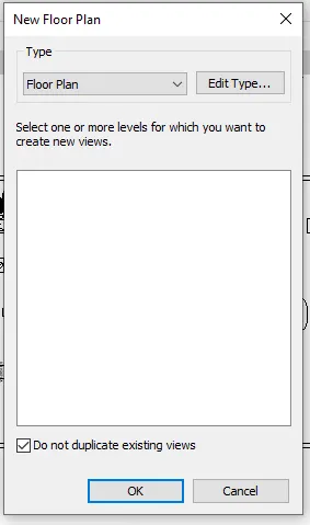
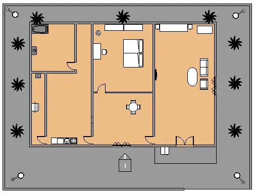
- Now we have to create the ground floor and first floor by selecting the respective level, as follows
- GROUND FLOOR
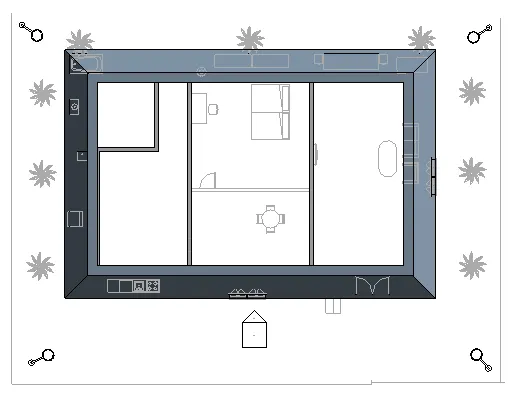
- FIRST FLOOR
- We can see these views in the properties browser.
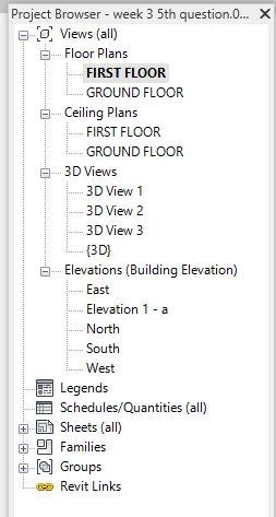
RESULT : We have created plan views for ground floor level and first floor level.
REMARK (WE WERE NOT TAUGHT ABOUT THE STRUCTURAL TEMPLATE AND PLANS)
4a)
AIM : To add dimensions to all the walls and floors with reference to the longitudinal and transverse grids created in the project file
TOOL/COMMANDS REQUIRED :
Architectural Template.
Wall.
Floor.
Grid.
Insert.
Families.
Elements.
PROCEDURE :
- Create a architectural template.
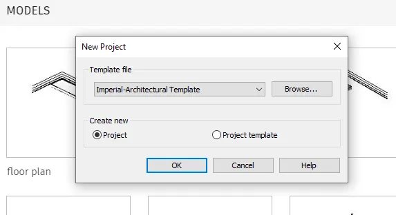
- Create a simple layout which includes walls and floor.
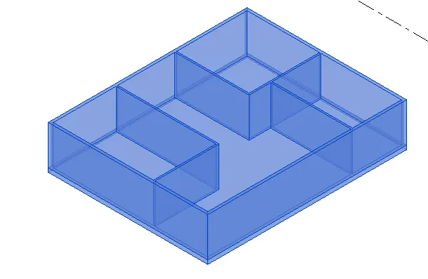
- Now in the toolbar we will find the architecture we have to select that.
- Now in that we will find the Grid option by using that we have to create grid for every wall in the project.
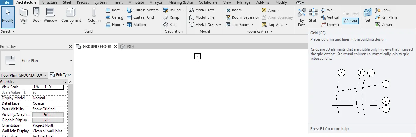
- We have to follow a simple procedure that while placing the grid in top to bottom way we have to name them as A B C D... and while placing the grid in right to left way we have to name them as 1 2 3 4...
- By using annotate tool bar and by selecting align option measure each and every wall and whole floor.
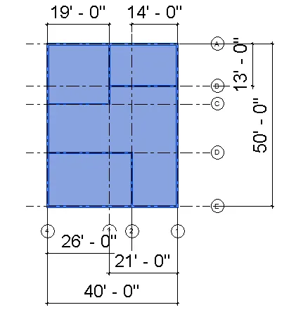
CASE A:
- To place the elements according to the grids we have to select the component option in the architecture toolbar.
- now while placing the elements we have to place them by checking the distance from each and evrey grid.
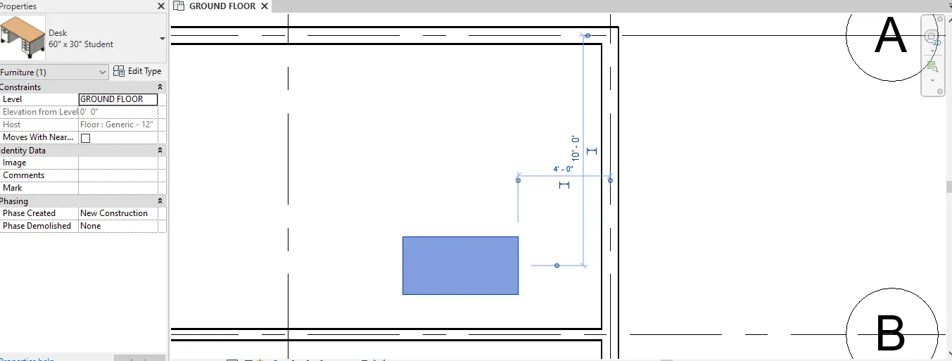
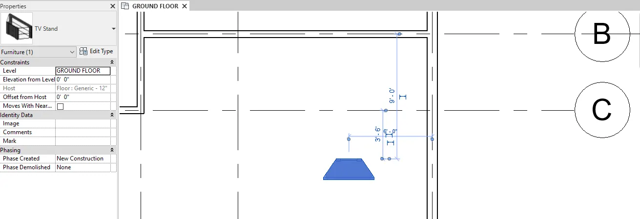
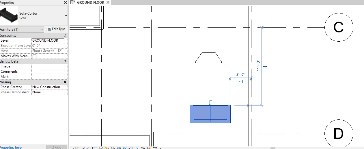
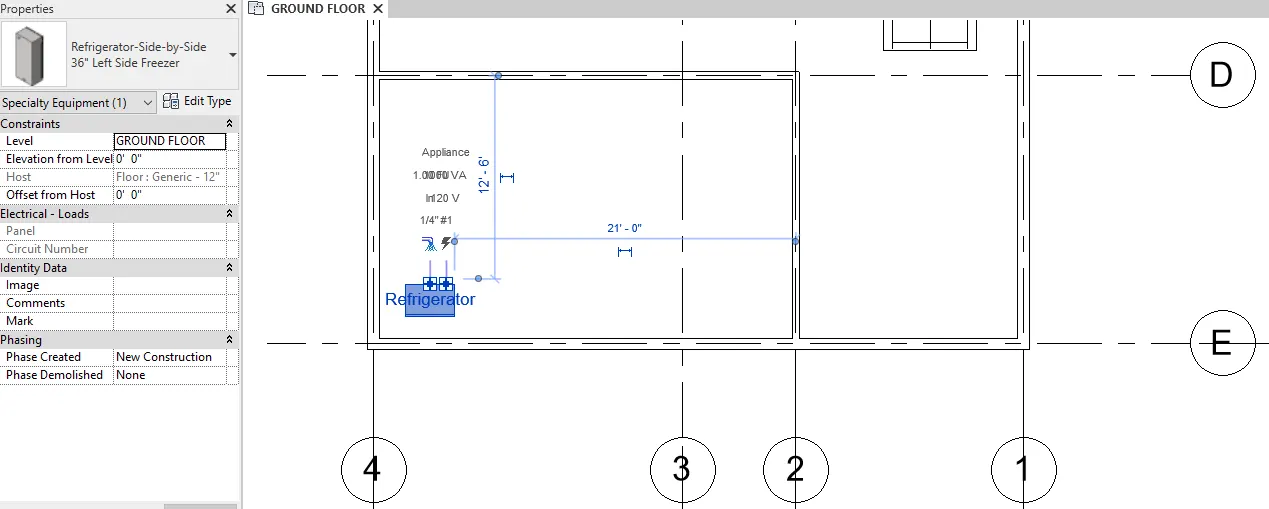
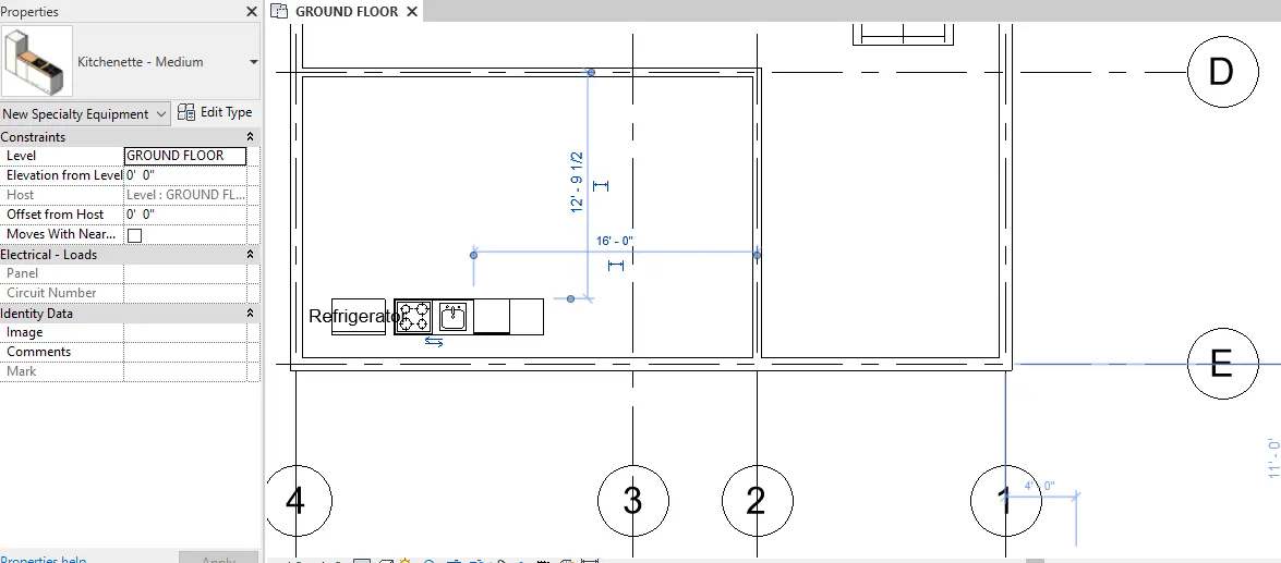
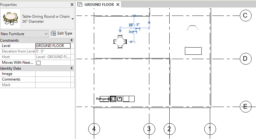
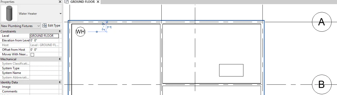
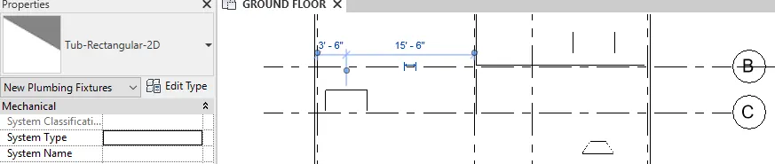
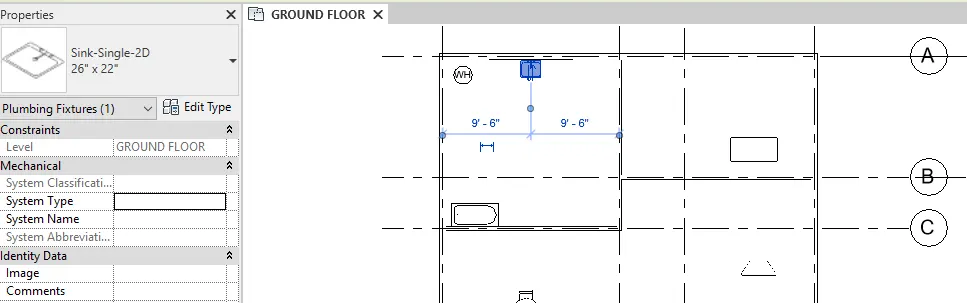
- If we want to change the position of the element according to the grid we can select on the dimensions and edit them according to our requirment.
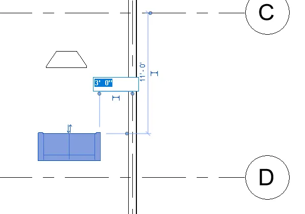
CASE B:
(NOT EXPLAINED IN THE CLASSES)
RESULT : Using grids we have placed thw walls, floors, and other elements as per our required positions.
5a)
AIM : To Create a sheet template from the view tab and adjust the parameters on the sheet to add appropriate views
TOOL/COMMANDS REQUIRED :
Architectural template
View
Sheet
Title block
Parameters
PROCEDURE :
- First we have to create a architectural template.
- In that we have to select view in the toolbar.
- In that we have the sheet option to create a sheet.

- Now we have to select the required title block for the sheet.
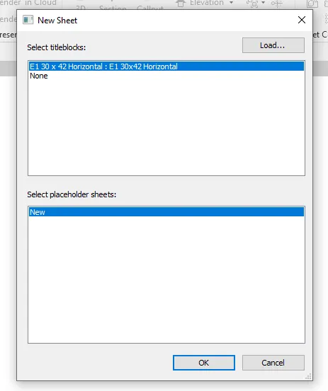
- Now the unnamed sheet will open.
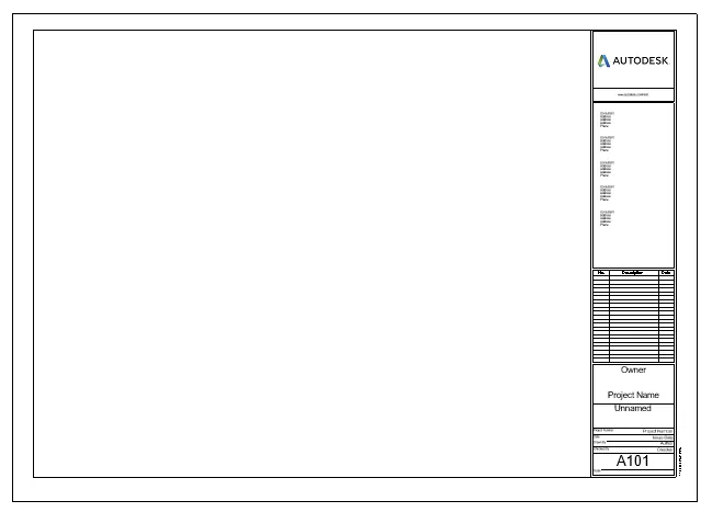
- We have to edit the information about the project in the properties.
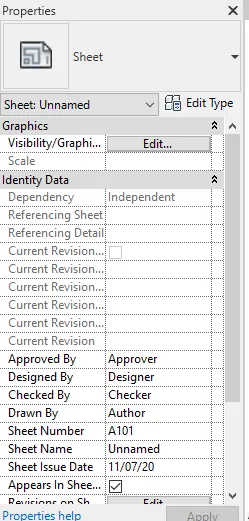
- We have editted the information.
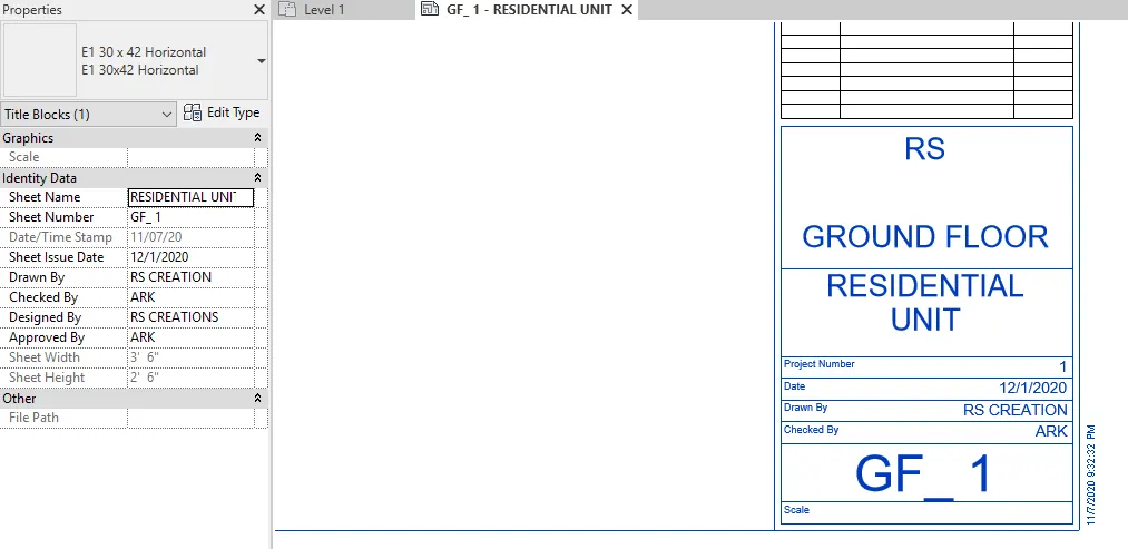
- Finally if we want to change the parameters then we should go to the edit type option on the left side.
- We can see the pop up menu on the scrren as type properties there we can change the parameters as per our covinience keeping in the mind about how many views we are uploading in the sheet.
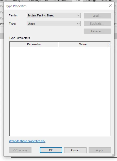
RESULT : We have Create a sheet template from the view tab and adjust the parameters on the sheet to add appropriate views
6a)
AIM : To create the elevation views of the building using elevation tab.
TOOL/COMMANDS REQUIRED :
Architectural template
View
Elevations
Property browser
PROCEDURE :
- create a Architectural template.
- In that we will find the view option.
- After selecting the view option we have to select the elevations in that view.
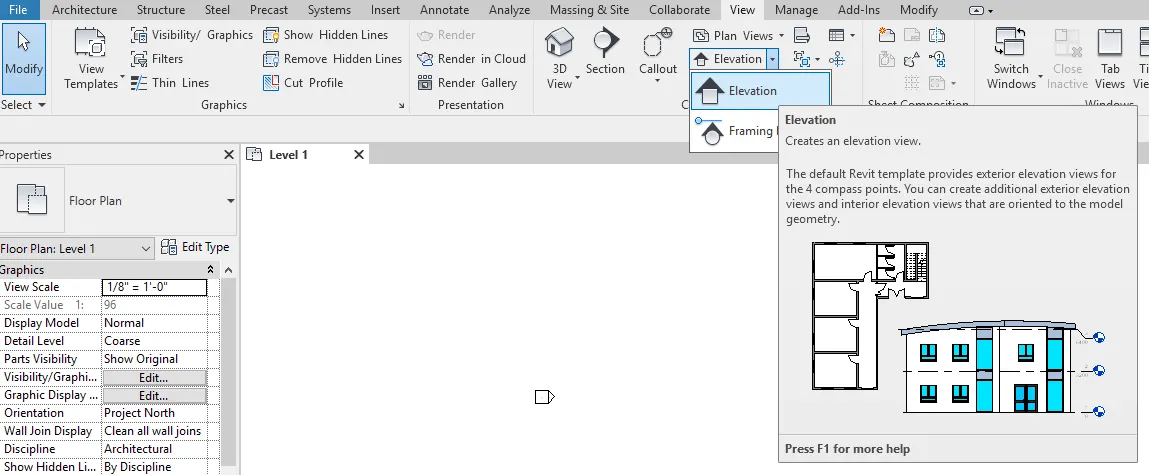
- then we have to select on the left side of the layout as west view.
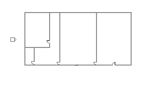
- We have to select on the right side of the layout as east view.
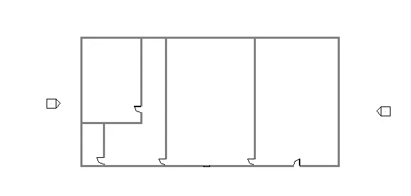
- we have to select on the top side of the layout as north view.
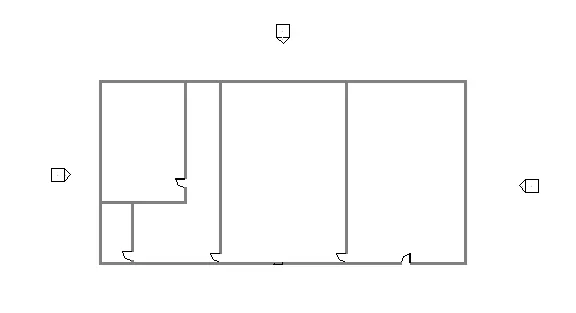
- we have to select on the down side of the layout as south view.
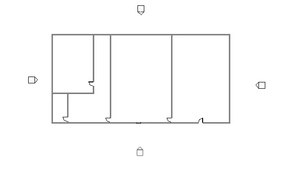
- now to view these views we have to select particular view in the properties browser.
RESULT :
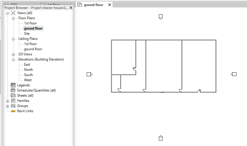
We have created the elevation views of the building using elevation tab.
7a)
AIM : To Produce section cut through each room either cutting across longitudinally or in a transverse direction.
TOOL/COMMANDS REQUIRED :
Architectural template
Walls
Floor
Elements
View
Sectional view
PROCEDURE :
- Create a project in which we have all the walls, floors, elements to each and every room.
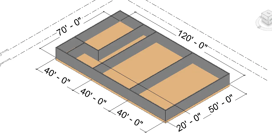
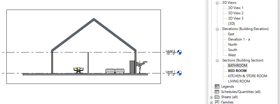
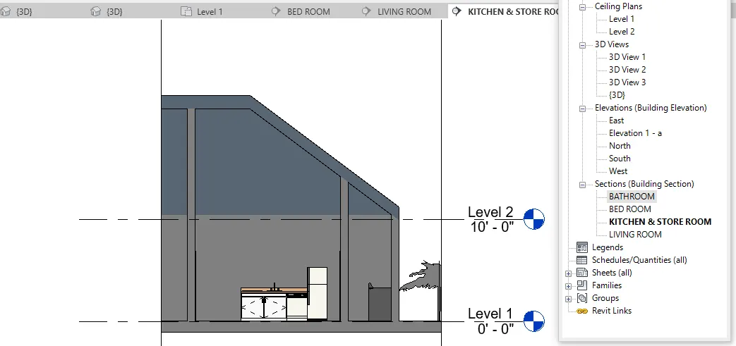
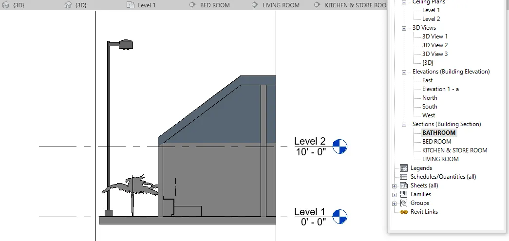
- To add a sectional view we have to go to the view toolbar and their we will find the sectional view beside 3D view.
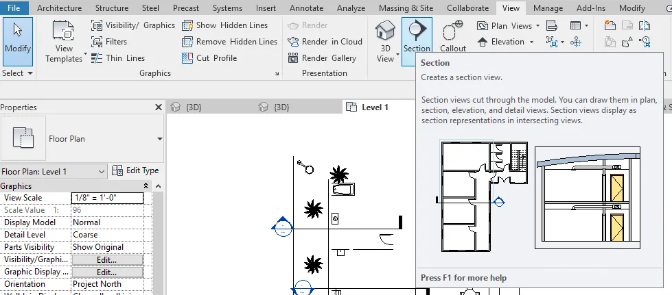
- Select that option and now to add the sectional view to each room we have to seclect that room os follows:
- LIVING ROOM
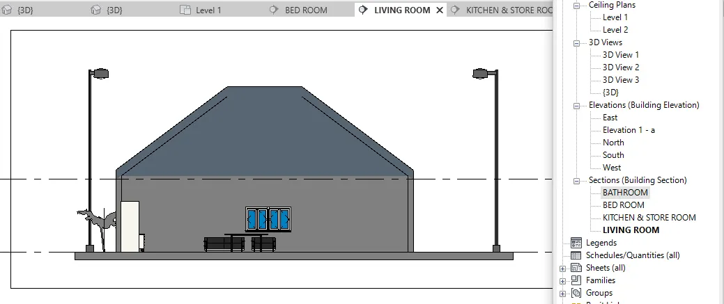
- BED ROOM
- KITCHEN AND STORE ROOM
- BATHROOM
RESULT : We have Produced section cut through each room either cutting across longitudinally or in a transverse direction.
8a)
To classify the views of the given project we have to goto the toolbar and there we will find the view option. now to discuss the views with clarity we will divide them into 3 categories first as 3D view, elevations views, plan views, sectional views.
3D VIEWS :-
The project that we have created to view it clearly we have a option as 3D view.in this every corner and every edge can be viewed clearly. adding to them we can also view the top view, front view, bottom view, back view, left view, right view.... By this way we can clearly know about the project and we can also present it to anyone with more efficient vision.
PLAN VIEWS :-
Under this category we can understand clearly about all the levels that are included in the project such as Level 1 as Ground floor, Level 2 as First floor, Level 3 as Second floor....
In this type of vision we can easily edit the elements that we have added to the project.
ELEVATION VIEWS :-
Now in this type of view we can see our project in all directions that is in EAST WEST NORTH SOUTH directions.
By this type of vision we can clearly identify the diffrence in the walls if any and edit them very easily.
SECTIONAL VIEWS :-
Sectional views are mainly used to cut through the model. You can draw them in plan, section, elevation, and detail views. Section views display as section representations in intersecting views. Open a plan, section, elevation, or detail view.
9a)
AIM : To create multiple sheets Using the sheet template produced.
TOOL/COMMANDS REQUIRED :
Open
View
Sheet
Titleblock
Properties
multiple sheets
Insert
Import image
PROCEDURE :
- Open the file that we have saved last week to add them to the sheets.
- For a project file to create sheet we have to select the view option in the toolbar.
- In that we have the sheet option.

- Select that option and we will see that a sheet will be displayed on the screen.
- We have to select which type of titleblock we need.
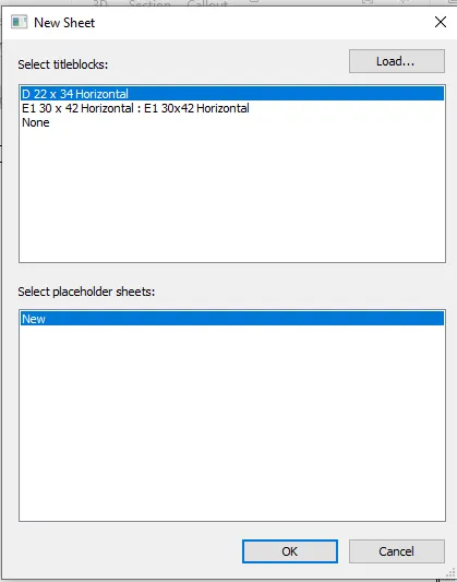
- Name the sheet as per our requirement in the properties menu.
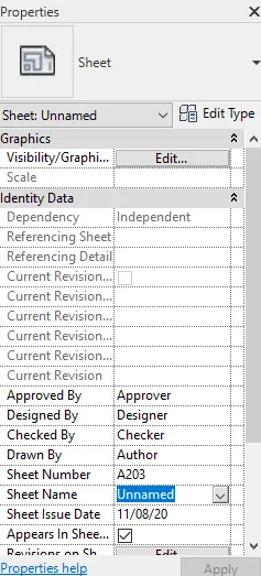
- repeat the same procees to create multiple sheets and name them.
- And after renaming we have import the image from the insert option from the toolbar.
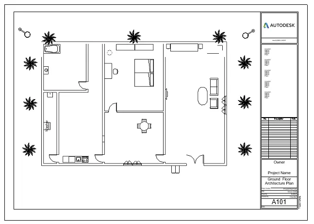
- The particular image should be imported to the particular sheet respectively as follows.
- a. A 101 – Ground Floor Architecture Plan
b. A 102- First Floor Architecture Plan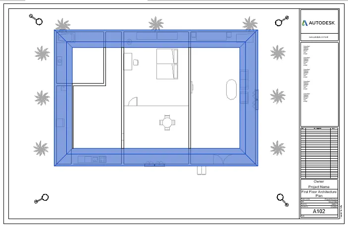
c. A 103- Roof Plan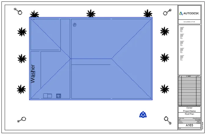
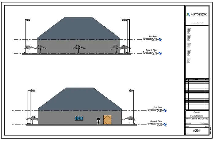
- d A-201 – North South Elevations
f. A-202- East West Elevations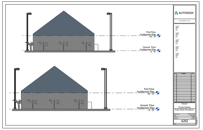
RESULT : We have created multiple sheets Using the sheet template produced.
10a)
AIM : To Create a camera specific view or a 3D view in each room and to create new set of sheets starting A-501 (you can add as many sheets after , 502, 503.. n)to place the 3D view images.
TOOL/COMMANDS REQUIRED :
Architectural template
View
Camera view
Sheet
PROCEDURE :
- Create a Project with the architectural template.
- In that include all the rooms i.e living room, dinning room, bed room....
- Now add all the elements in the specific rooms repectively.
- Now to create a camera specific view we have to select the view option in the toolbar.
- Now we have to select the 3D option to view the drop down menu in that we have camera specific view option.
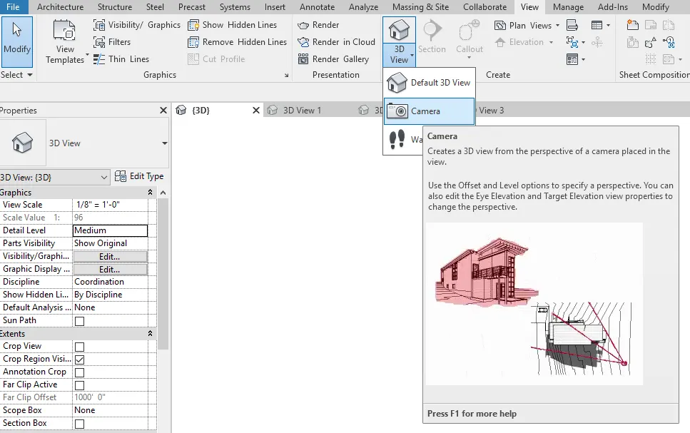
- Select that option and place the camera in a particular position so that whole room will be visible.
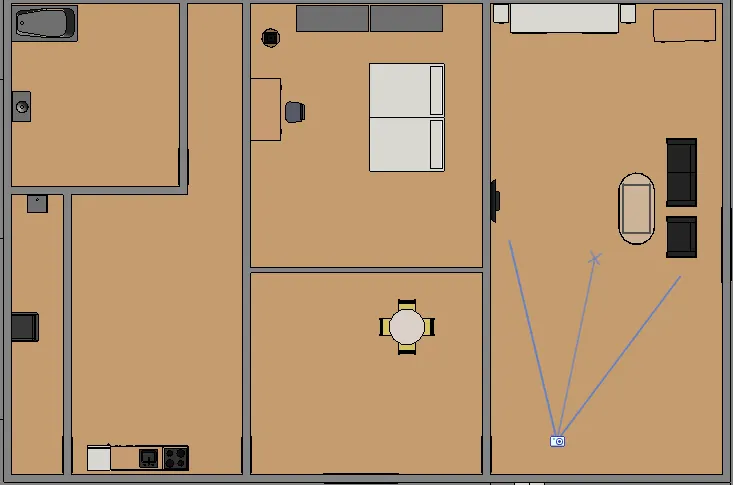
- Now same as the above process create a camera view for every room.
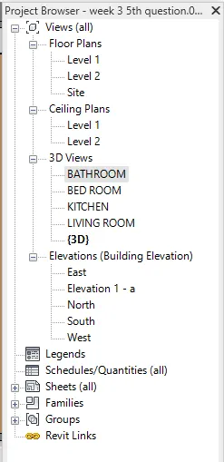
- We can see all the camera vies in the property browser.
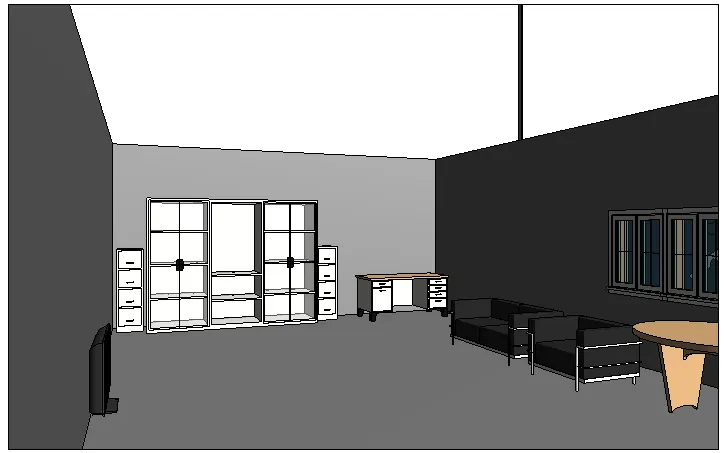
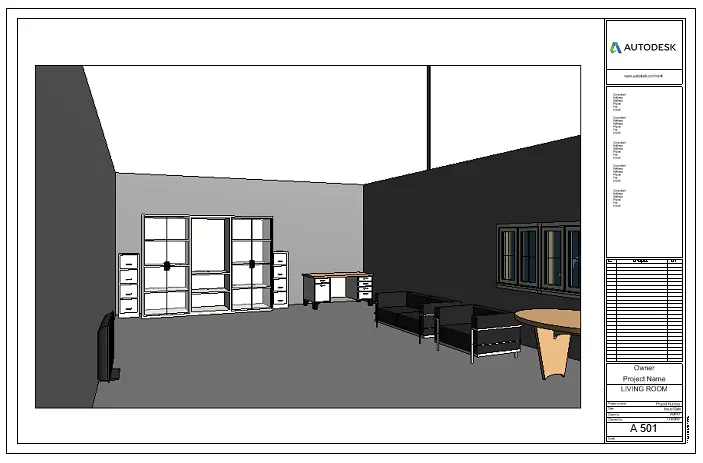
- LIVING ROOM
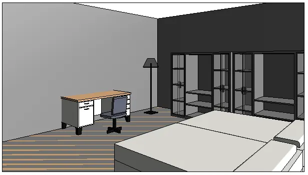
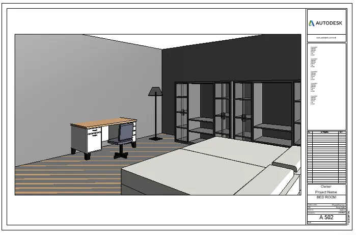
- BED ROOM
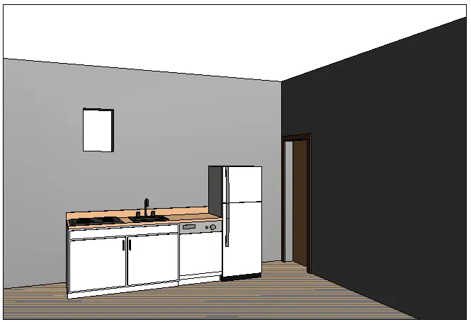
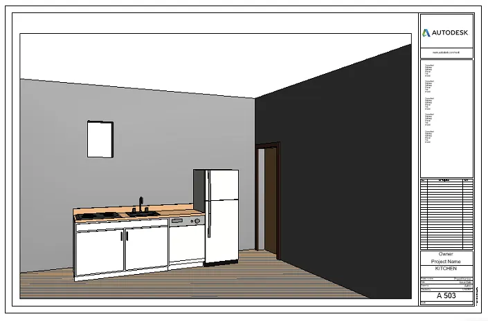
- KITCHEN
- BATHROOM
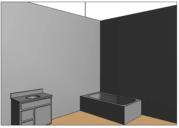
- Now create the the sheets for every camera view with appropriate naming. as follows
- LIVING ROOM SHEET
- BED ROOM
- KITCHEN
- BATHROOM
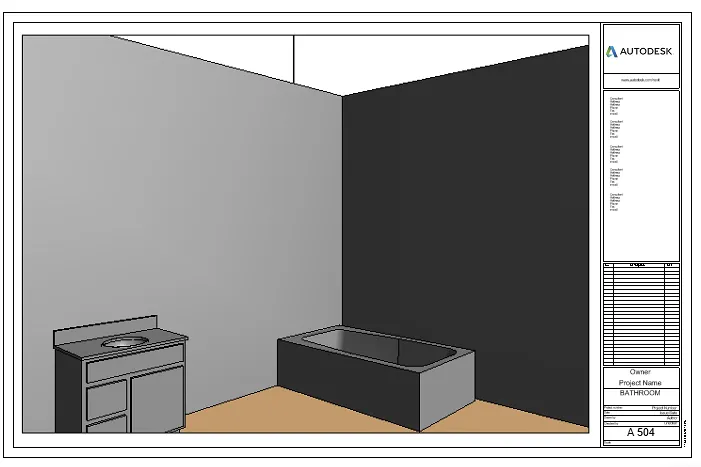
RESULT : We have created a camera specific view or a 3D view in each room and new set of sheets to place the 3D view images.