Week 2 Challenge
1a)
BIM : BUILDING INFORMATION MODELLING
- In revit BIM is rather than a software it is process.
- Mainly BIM is divided into two core concepts they are: A. Coordination B. Computation
- Using autodesk revit we can get coordination with multiple disciplines
- If we think revit as a BIM tool it will perform computations such as material schedule, quatity schedule,how to perform energy evaluation or analysis or different tolls associated with revit.
- Autodesk revit is used to activate the coordination and computation as a part of our project and modelling purpose.
Key benefits
- Achieve faster design times.
- Establish the best solution quickly
- Manage changes easily
- Maximize profitability and efficiency
2a)
Cotegories in revit means the options that we get after opening the tools. Families in revit is actually defined as what ever the elements that you add to our Revit projects such a walls, roofs, doors, structural members, mechanical equipment, or plumbing fixtures; or even annotation elements such as elevation symbols, door tags, and column gridlines.
AIM : To Understand the concept of Categories, Families, Elements, Instances in Revit.
TOOLS/COMMANDS REQUIRED :
Insert toolbar
Load family
Impeirial libraries
PROCEDURE :
- firstly in the toolsbar menu click on the insert option.
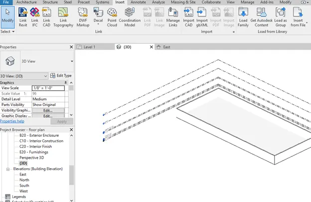
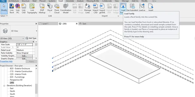
- we will find the load families option we should click on that.
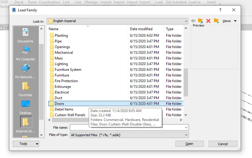
- the imperial libraries will open in that we have to select our required category.(ex.doors)
- we have to select on our required family.(ex. door sigle flush, door double flush etc).
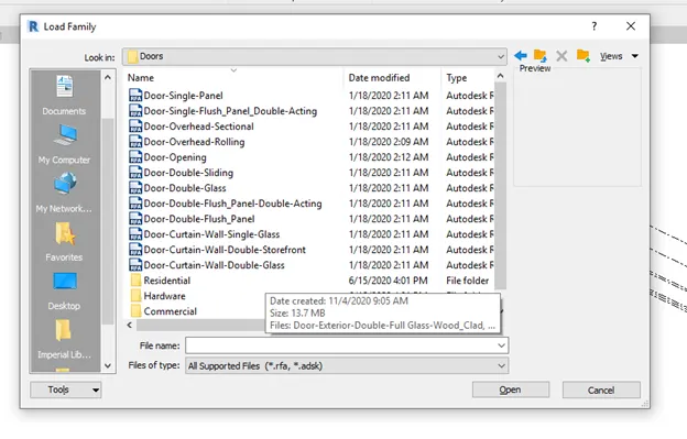
- we have to select our required element (ex. door double flush)
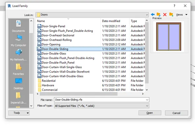
- finally we have inserted our required element in revit.
RESULT : we understood the concept of Categories, Families, Elements, Instances in Revit.
3a)
AIM : To set up a project.
TOOLS/COMMANDS REQUIRED :
Architectural template
File
Save as
File save option
PROCEDURE :
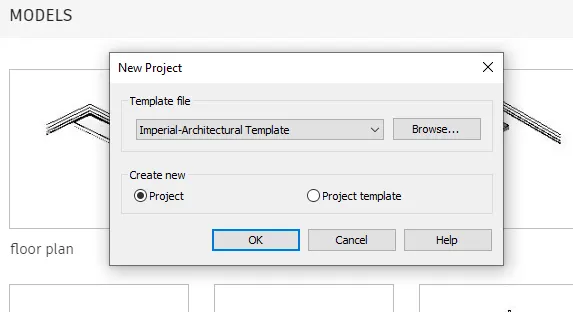
- on the main page of the revit software we have to click on the new option in that we have to select imperial architectural template and project in down options.
- And after creating a project. we have to go the manage toolbar and there we will find the project information option and on clicking on that we can save every information about the project.
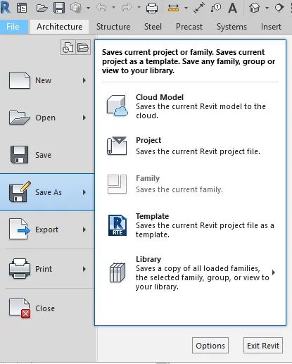
- Now to save the file we have to go to the file menu bar and in that we have to click on the save as option.
- After clicking on the save as option we have select the option in the window that will open on the screen there we can change the maximum backup setting.
-
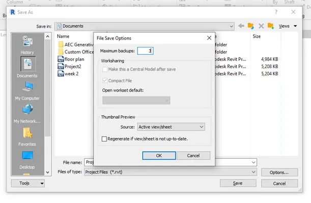
- At last after giving a appropriate name to the file on clicking on save option the file will be saved.
RESULT : I understood the procedures to save the file, write the project information, and setting the maximum backup for a project.
4a)
Levels and grides in revit are really like backbones for building projects. The levels in revit are used to indicate the locations of floors, foundations, and the roof of the building in section and as well as elevation views. Grides are used to represent the columns, pillars and walls. Levels and Grides both should be setcorrectly otherwise it will create more confusion.
AIM : Create the following Levels:
Ground Floor @ 0’
First Floor @ 10’
Second Floor @ 20’
Roof @ 30’
TOOLS/COMMANDS REQUIRED :
Construction template.
Architecture tool.
Elevation.
Levels.
PROCEDURE :
- Open the new construction template.
- In the toolsbar menu we will find the architecture tool.
- selecting that option we will find the levels option on th right side of the drop down menu.
- we have to go to the view and then elevation then we can draw different levels with different distances.
- It will defautly set levels name as level 1, level 2 etc we should rename them as follows
- 1. level 1 - ground floor @ 0'0"
- 2. level 2 - first floor @ 10'0"
- 3. level 3 - second floor @ 20'0"
- 4. level 4 - roof @ 30'0"
- Thus we can create our required levels.
RESULT :
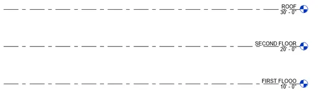
The required Levels are formed as per our requirment.
AIM : Create the following Grid:
Transverse Grids A, B,C,D, E @ 10’ spacing
Longitudinal Grids from 1 to 10 @ 20’ spacing
TOOLS/COMMANDS REQUIRED :
Construction template.
Architecture tool.
Elevation.
Grid.
PROCEDURE :
- Open the new construction template.
- In the toolsbar menu we will find the architecture tool.
- selecting that option we will find the grid option on th right side of the drop down menu.
- On clicking on that option we can draw different grid with different distances.
- for the longitudinal grides we have to give 20' gap b/w each of them and name them as 1 to 10 from right to left.
- for the Transverse Grids we have to give 10' gap b/w each of them and name them as A B C D E from top to bottom.
RESULT :
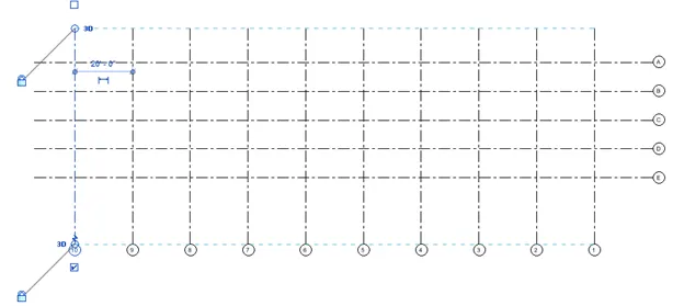
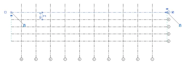
The required grids are formed as per our requirment.
5a) AIM : To design a 3D modelling of residential unit.
TOOLS/COMMANDS REQUIRED :
Project template
Tools
Architecturlal Tool
Annotate
Align
PROCEDURE :
- Create a new project.
- In the toolbar select architecture.
- select the required wall.
- Using the wall select the line command
- create a layout of our inspiration.
- In the toolbar menu we have annotate option in that we have to select the align option to give the dimensions or measurement to the layout.
- After clicking on that to start giving dimensions we have to select the left end of the layout and then drag it to the right end.
- similarly select the align option and select the top end of the layout and drag it to the bottom end and then drag it outwards from the layout to represent it.
RESULT :
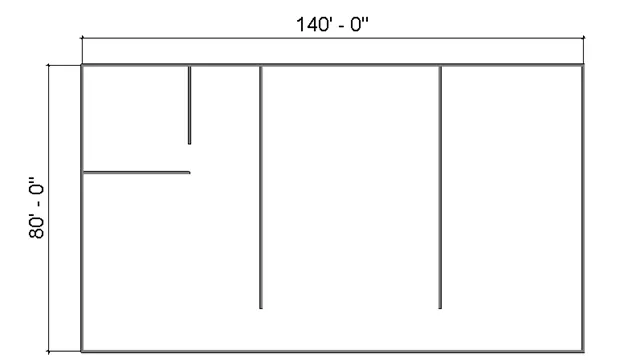
This will be the final 3D vision of our layout with dimensions.
6a)
AIM : To draft the level of details you are planning and to include – Dimensions of room, components you plan to add in the residential unit.
TOOLS/COMMANDS REQUIRED :
Project template
View
Elevation
PROCEDURE :
- create a layout with rooms.
- For the created layout along with the rooms inbuilt in it. firstly we have to select elevation view in it and set all elevations (Ex. east, west, north, south) properly by selecting a wall which is not in same elevation and draging it to the required elevation in oreder to get a exact model.
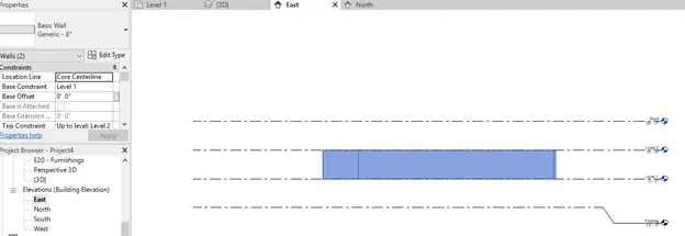
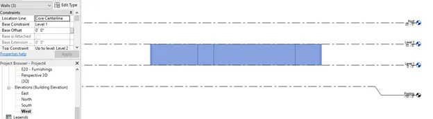
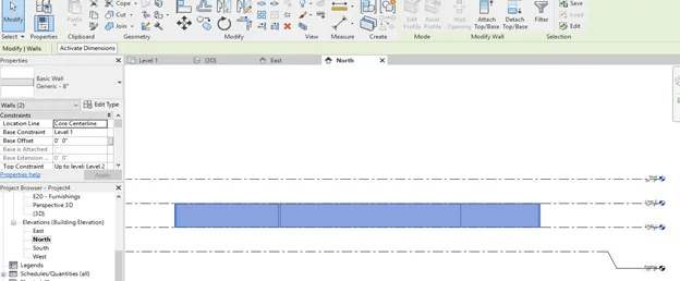
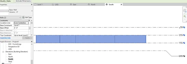
- To give the dimensions or measurements go to the annotate toolbar and select align option.
- Then by selecting each and every room's top and bottom otherwise left and right side corners to assign dimensions.
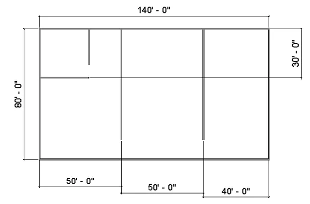
- After selecting drag them outwords inorder to represnt them very clearly for each and evry room.
RESULT : The levels and dimensions for the created layout has bee assiged successfully.
7a)
AIM :TO Identify the residential model elements such as Door, Windows, Tables, Chair, Couch, Bed, Lamps from the library and insert them to the model .
TOOLS/COMMANDS REQUIRED :
Project template
Architectural tool
Wall
Doors
Components
PROCEDURE :
- Create A new project as per our convenience.
- go to the Insert tool bar and select load families
- And then after clicking on load families we can select any category and elements which we need to insert in our project .
RESULT :
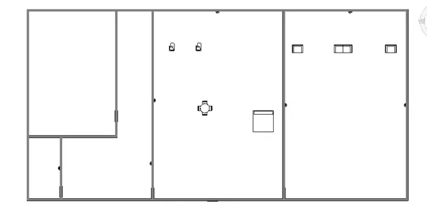
The final view will represnt the project with Doors, Windows, Tables, Chair, Couch, Beds, Lamps