Week 3 Challenge
1a)
AIM : To create the floor plan for the given layout, Align the floor plan with grids.
TOOLS/COMMANDS REQUIRED :
Acrchitecture TOOL
View
Elevation
Grid
Annotate
Align
PROCEDURE :
- Browse the saved layout.
- In the toolbar you will find the view tool we have to open that'
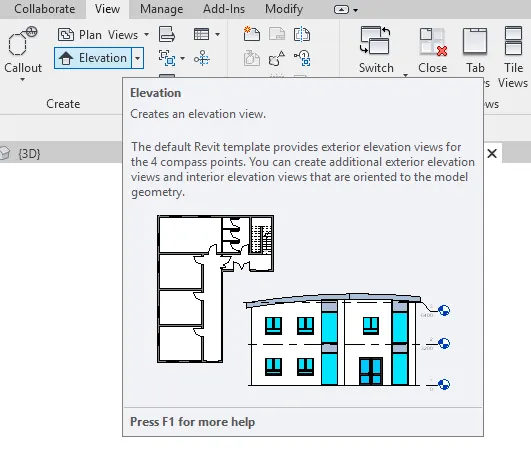
- we will get the drop down menu in that we have select the elevations and we have to set the whole layout to the first floor by selcting TOP CONSTRAIN as upto level first floor.
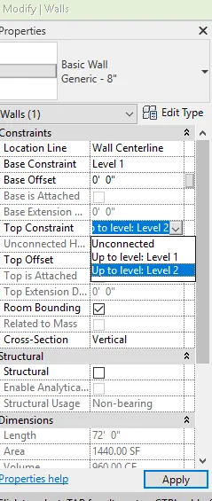
- Now we can see that each and every wall of the project is at similar height in the elevation view.
- we have to select the Architecture tool in that we have to select the floor option to create a floor to the project.
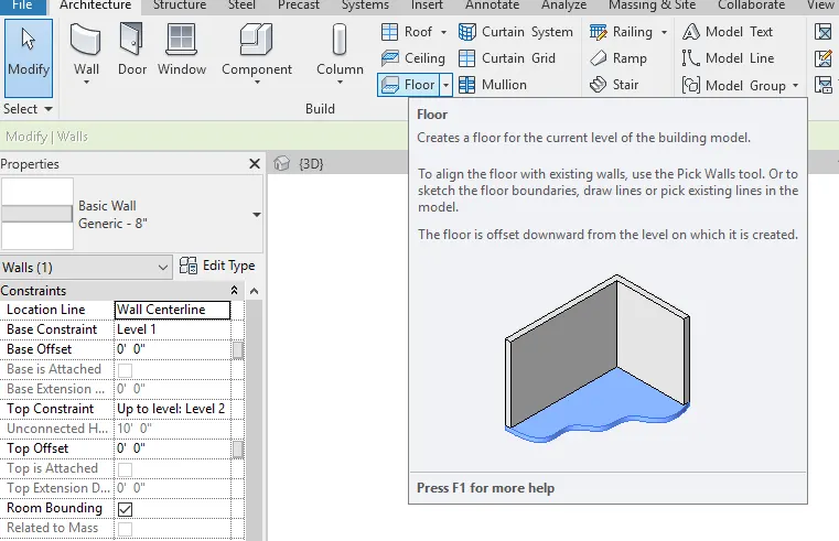
- After selcting the floor we have to select the pick walls option which is on the right side of the drop down menu.

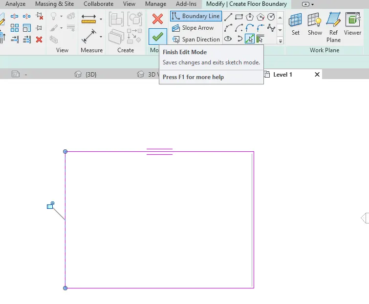
- Now we have to select the exterior side of the wall and pick the wall like that we have to select all the exterior sides of the wall without any discountinues otherwise it will show a error that there are some discontinues.
- After completion of selection of all the exteriors of the wall we have to tap on apply button which is in the drop down menu as a green colour tick mark.
- Now we have to select our required matertial and thickness.
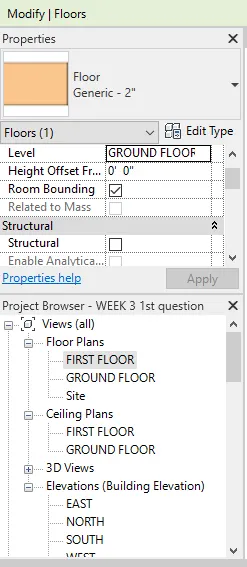
- In that if we not have the our required material and thickness we can edit it as per our requirement.
- After appling the changes the floor for the layout is created.
- Now in the same architecture tab we can see the grid option on the right side.
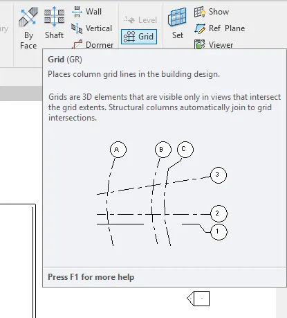
- We have to select that and draw the grid lines by selcting the starting point and ending point of the walls.
- We have to follow the standard procedure i.e from top to bottom the grid lines should be named as A B C D.... and from right to left the grid lines should be named as 1 2 3 4...
- The required gride lines for the given layout.
- At last we have to annotate the layout by using Align option.
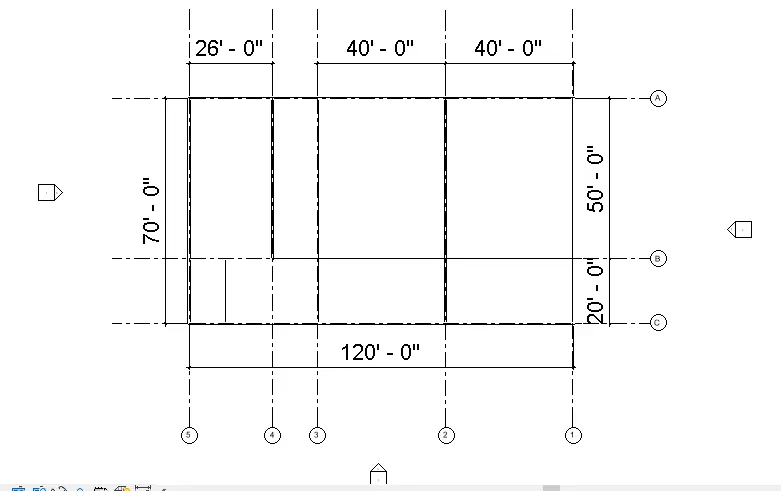
RESULT : We have created the floor for the layout and we have created grid lines to align the layout.
2a)
AIM: To create a layout with walls and floor and modifing them.
TOOLS/COMMANDS REQUIRED:
Architectural template
Wall
Floor
Modify
PROCEDURE:
- Create a architectural template as a project.
- In this we have to select the architectural tool and in that we have to select the wall option to create a layout.
- We have to select the specific wall that we need from the properties section.
- After creating a layout with the rooms included in it we have to select the floor option from the architecture toolbar.
- After selecting the floor we have to include it to tthe layout.
- Now if we want to change the materials and thickness of the floor or a wall we can do it from the properties browser as follows:
- 1. Firstly click on the wall which you want to change the property.
- 2. You will find the wall that you are currently using on the left side.
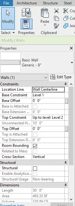
- 3. Under that you will find the edit type option we should select that.
- 4. Then type properties menu will open then in that we have to select structure.
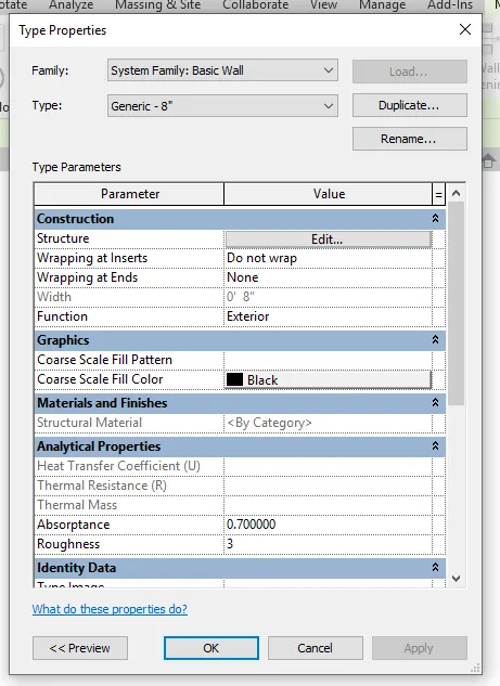
- 5. In that we will find By Category option in the material column.
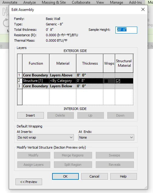
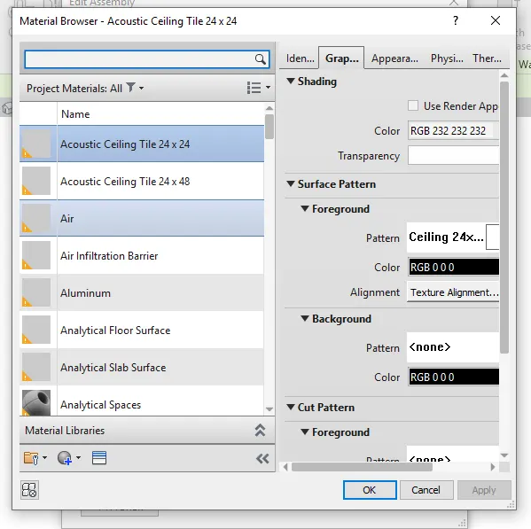
- 6. On selecting that we can change the required material and thickness.
- If we actually see cleraly in the 3d view we will see that the floor and the wall get mixed with eachother.
- Now if we want to modify the walls we should use the picklines and set the walls as per the requirment.
RESULT:
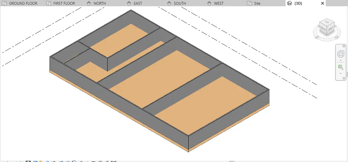
The whole layout along with walls and floors has been modified after created by using drawing tools and picklines.
- a) As per my observation the connecting walls with associated levels add much benefit for over future pupose, if we connect all the walls to the particular level and fix it there if in future we change the level distance then the wall which is connected to that level also will rise or fall to the same level that we change. And by this we will not face any problem in our work that we progress.
- b) by modelling the walls by heights is very convinient because the heights of walls that we create will be extending upwards. In this type of vision we can understand very clearly as we are habituated to it.
3a)
AIM: To copy and paste the model elements to one level to different levels using modify tab.
TOOLS/COMMANDS REQUIRED:
Architectural template
Wall
Floor
Copy to clipboard
Paste
PROCEDURE:
- Create a architectural Template.
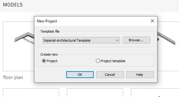
- In that create a simple layout of atleast of 3 - 4 rooms.
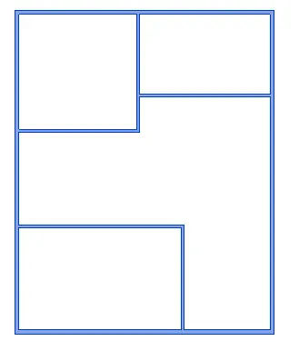
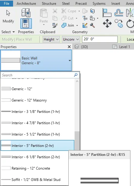
- For creating a layout use the generic wall of the required instances, and for creating the interior walls use interior partition wall of required instances.
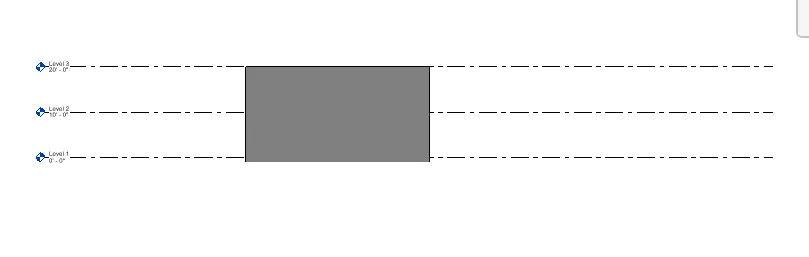
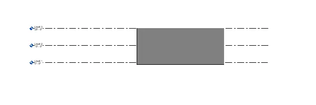
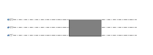
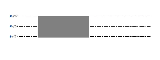
- After creating the layout we have to check the elevation view.
- In that if the wall are not adjusted to the required levels such as level 1 as ground floor, level 2 as first floor, level 3 as second floor, we can change it in the properties.
- And we have to set all the walls at the same height and in all elevations such as EAST WEST NORTH SOUTH.
- Now we have to include the floor to the designed layout by using architectural tool.
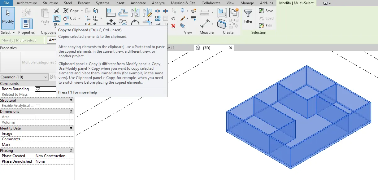
- We have to select the whole layout along with the floor and on the left side of the screen we can see the option of copying the whole to the clip board.
- Now we have to select the first floor in the levels and then we have a option pasting whatever thing that we have copied earlier.
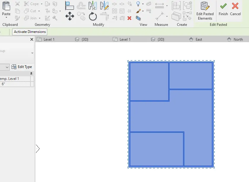
- After pasting then the first floor same as the ground floor has been created.
RESULT:
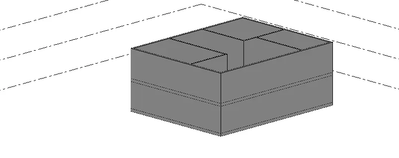
we have copied model elements from one level to the another level successfully.
4A)
AIM: To create separate rooms within your residential unit using interior walls and create all the rooms in that.
TOOLS/COMMANDS REQUIRED:
Architectural template.
Wall
Project properties
Room tags
PROCEDURE:
- Create a project of a architectural template.
- Select wall of required instance and create a residential layout of the assumed dimensions.
- Now select the interior partition wall to design the interior rooms of the residential unit.
- After drawing the rooms as per the required layout alog with the layout dimensions, we have to go to the Architecture tool.
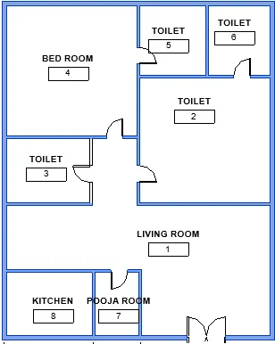
- There we have to select room tag and for each and every room we have to give a tag (EX.bed room, kitchen etc...)
RESULT:
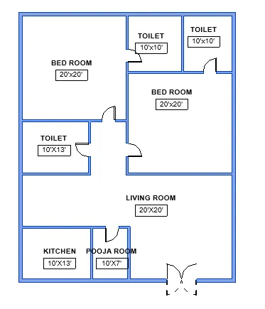
We have created a plan layout by using interior partition wall and given the room tags to them.
5a)
AIM: To include the libraries to the residential unit.
TOOLS/COMMANDS REQUIRED:
Insert
Library
Load families
Category
Families
Element
Instances
PROCEDURE:
- Firstly we have to open the layout that we have saved previously.
- Now we have to Place Doors and windows in the wall at appropriate locations from the revit library.
- The Living Room must include furniture set, couch table and TV desk and shelf cabinets from the revit library.
- The Dining Room must include a table and chairs serving the purpose of eating from the revit library.
- Bed Room must include a bed set, shelf, lighting and individual study desk and chair from the revit library.
- Rest room should include bath tub and plumbing fixtures discussed in class from the revit library.
- Kitchen should include countertops, gas stove cabinet and shelves to store food items from the revit library.
- The wash/storage room can include washing machines and shelves to store clothes from the revit library.
RESULT:
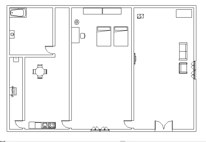
The required final layout has been created.