Week 1 Challenge
1a) AIM : To create a revit file and Naming a file
TOOLS/COMMANDS REQUIRED :
file menu
open
PROCEDURE :
A. first when we open the autodesk revit app after opening the app we will find a file icon on the top left corner.
B. on clicking on that icon we will get adrop down menu, that we should click on new option, and when we click that option we can create a new project.
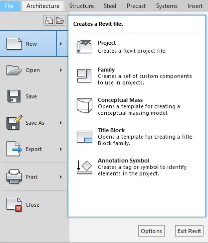
C. click on new project then we have to select what type of project we want such as Structural / Architectural / Construction template.
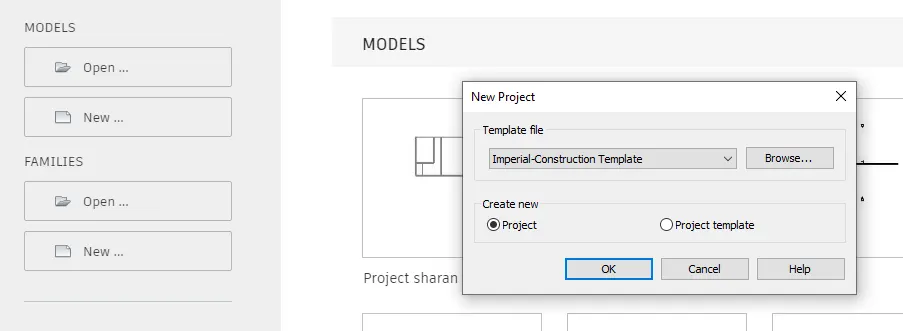
RESULT : Finally we have created new project and named a project.
2a) AIM : To Save File ,Open The File and close the file
TOOLS/COMMANDS REQUIRED :
file
save as
name the file
PROCEDURE :
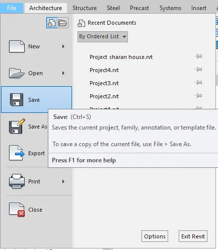
A. Go to the menu bar there we will find a save option.
B. on clicking on that option we will get the drop down menu in that we should select the location that where we have to save the file.
C. finally on clicking on save button the file will be saved.
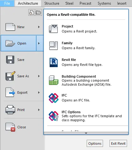
D.on the main window of revit app we will find the file icon on the top left corner of the toolbar.
E. on clicking on that option.
F. A new window will be opened in that we have to select the file which we have saved already in our local computer.
G. on selecting that file the file will be opened.
H. in the same file toolbar we will find the close option as a last option.
I. on clicking on that option current file will be closed.
RESULT : finally we have saved a file, opend it and then at last closed it.
3a) AIM : To Create a rectangular layout.
TOOLS/COMMANDS REQUIRED :
architecture
wall
PROCEDURE :
A.In the toolbar of revit we will find the architecture/ structure tool bar.
B. After selecting that toolbar we will find the wall option.
C. After selecting that option we will redirect to a modify toolbar in that we will find the shapes like straight line, rectangle,rhombus etc...

D. selecting rectangle in that we can draw a rectangle with reqiured dimensions.
RESULT :
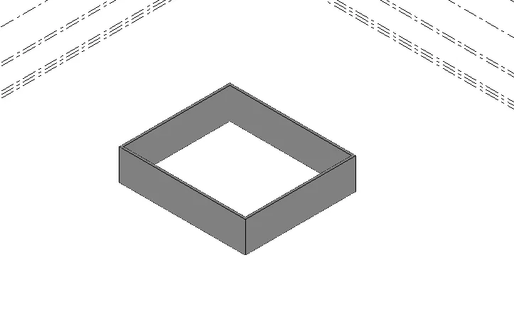
hence rectangle with wall is created.
4a)AIM : measuring a wall using allign option in toolbar
TOOLS/COMMANDS REQUIRED :
annotate
aligned
PROCEDURE :
A.firstly we have to draw a wall using wall option.
B.And using annotate option in toolbar we can open align option.
C. After equiping that align option we have to select the starting point of the wall that we have already prepared.
D. And we have to drag the selected one to the end point and click there, then we will get the measurement of the wall.
RESULT :
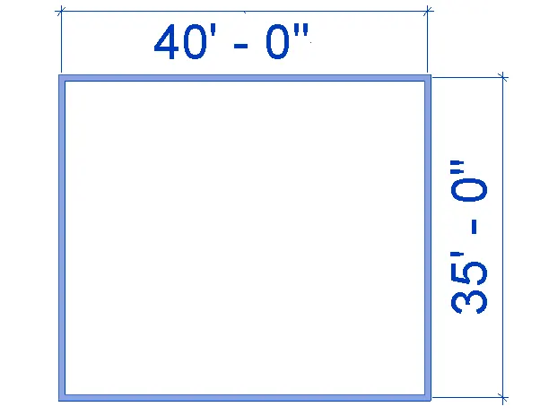
Finally We have measured a wall dimensions using Align toolbar.
5a)AIM : Selecting diffrent types of walls
TOOLS/COMMANDS REQUIRED :
properties
PROCEDURE :
A. first we have to go to architecture toolbar and select that option.
B.In that we have to select the wall and prepare a basic wall.
C. upon selecting the wall which we have created the properties will open on the left side.
D. In that properties we can see the diffrent types of walls such as curtain walls,stacked walls ect.
RESULT :
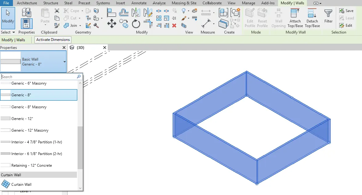
Finally we have selected different wall types using toolbar.
6a) AIM : To Create a 3D view from the view tool bar and save the view with appropriate name
TOOLS/COMMANDS REQUIRED :
view
3D
save
rename
PROCEDURE :
A. By using a rectangular shape in a architecture toolbar draw a wall.
B. In the toolbar select the view option and in that select the 3D view option.
C. Then you will view a 3D vision of the wall.
D.we will find the 3D cube on the right side and there is a option to save the view.
E. click on that and save the view.
RESULT :
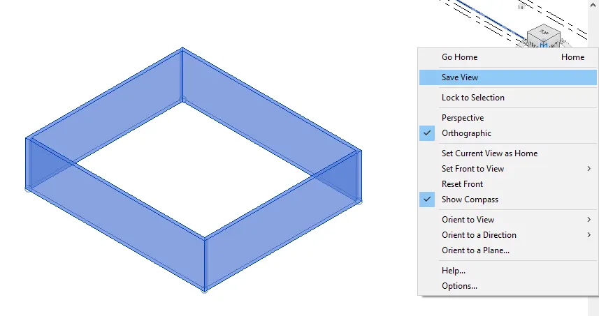
Finally we have created a 3D view and named it appropriatly.
7a) AIM : To Navigate through the 3D model using view cube and To Orbit/pan through the model layout created.
TOOLS/COMMANDS REQUIRED :
navigation wheel
PROCEDURE :
A. Create a 3D view using toolbar.
B. On the top right corner we will find the viewscube in that we will find TOP VIEW, BOTTOM VIEW, FRONT VIEW, BACK VIEW, SIDE VIEW.
C. We can select our required view to view it.
D. On the right side e will find the option of Orbit and Pan.
D. Orbit is the option to change the fixed pivot point,Pan is used to move the present view of the project.
RESULT :
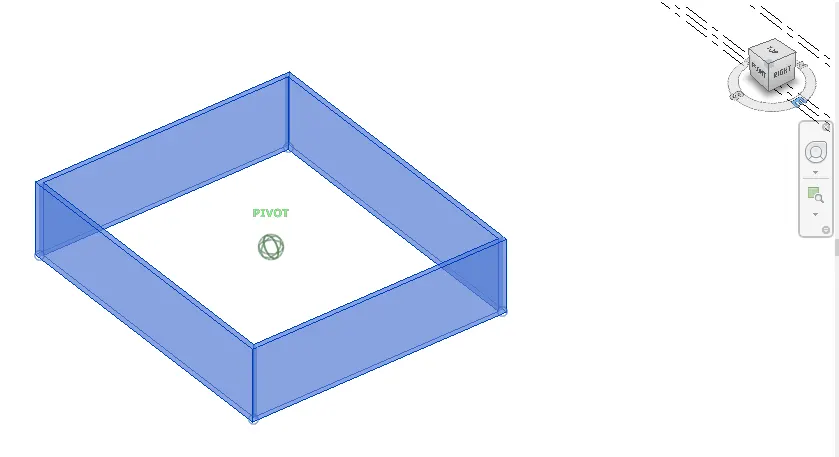
We have navigated through the 3D model using view Cube and used Orbit and Pan.
8a) AIM : To Use the visibility settings option below to switch model to shaded, realistic, hidden lines options
TOOLS/COMMANDS REQUIRED :
graphics display command
PROCEDURE :
A. Firstly create a model which we want to switch to diffrent graphic displays.
B. Now we have to click on the graphics display options given below'
C. If we click on that option the pop up menu will be opend, in that we can select the option such as shaded, realistic, hidden lines options as per our convenience.
D. Then we can view our preffered graphic displays.
RESULT :
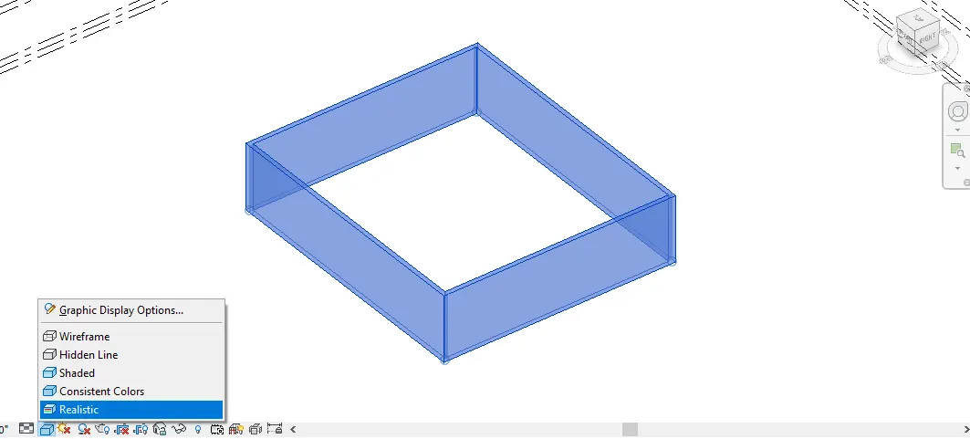
We have created a model switched it to different displays.
9a) AIM : To Turn the sunlight on and off to view shadings in the layout created.
TOOLS/COMMANDS REQUIRED :
sun settings
PROCEDURE :
A. fristly prepare a layout and set a particular view to that layout.
B.On the main screen of the window we will find the sun settings on the down menu bar.
C. on clicking that option we can change sunlight on and off settings.
RESULT :
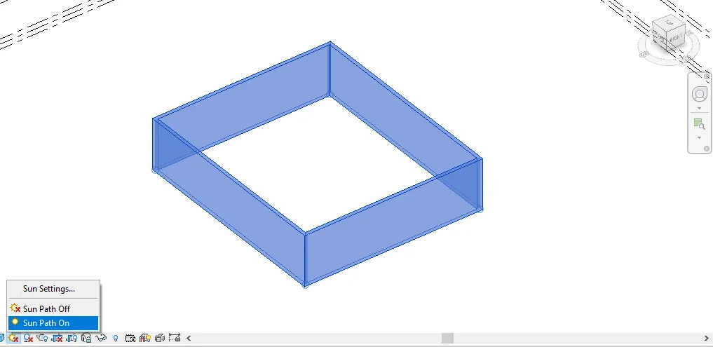
We have succefully turned sunlight on and off to view shadings in the layout.
10a)AIM : To Use the Manage tool bar to enter project settings, project name and project issue date.
TOOLS/COMMANDS REQUIRED :
manage
project information
PROCEDURE :
A.Firstly create a project and to save the project information we have to go to the manage option in the tool bar
B.In the manage option we will find the project infomation option on the left side.
C. There we can save every information regarding project such as project settings, project name and project issue date etc.
D. This is very important to save the project nformation first itself because at last if we want a sheet regarding project we will get the it prefilled.
RESULT :
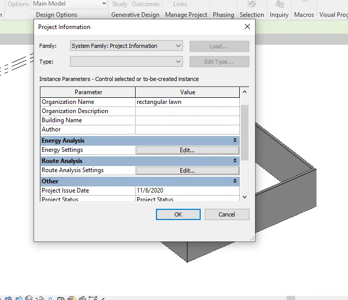
project settings, project name, project issue date has been saved succesfully using manage toolbar.
11a) analyze toolbar is used to perform calculations on loads and their combinations, boundary conditions and more. Analyze toolbar is used to analyze the structure with all the different loads applied in the objects and also gives the analysis report as the result.analyze toolbar is also used to detect the failures in the model.
12a) There are some types of links that support the REVIT, they are:
A. LINK REVIT.
B. LINK IFC.
C. LINK TOPOGRAPHY.
D. LINK CAD.
13a) collaborate in revit is a service which allows every user of revit that may be included members or non included members in the network to collaboratebon the revit model. by this service many users can work on the same plan or model which hwlps in making the work faster and very productive because if many people work on the same project the time will be reduced i.e work will be completed before deadline.