SHELL MESHING FOR A CAR INSTRUMENTAL PANEL/DASHBOARD
AIM: To Extract mid surface and create the two-dimensional mesh for the given Instrumental Panel according to the given quality criteria by using ANSA
THEORY :
DASHBOARD :
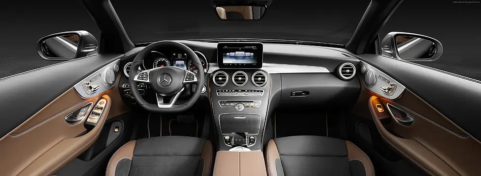
MERCEDES BENZ C CLASS 220 D DASHBOARD
A dashboard (also called dash, instrument panel (IP), or Fascia) is a control panel usually located directly ahead of the driver of a vehicle, displaying instrumentation and controls for the vehicle's operation.
where the dashboard originally included an array of simple controls (eg: steering wheel) and instrumentation to show speed,fuel level and oil pressure. the modern dashboard may accommodate a broad array of gauges and controls as well as information, climate control and entertainment systems.
FEA : FEA is a FINITE element analysis is a numerical method for solving problems of engineering and mathematical physics.
GIVEN MODEL : First we have to extract mid surface and then mesh this component by 2D mesh as per the given quality criteria.
KEYWORDS : Import CAD model, assign mesh length, geometry check, measurement, extract mid surface, meshing, assign new PID.
ABSTRACT : In this instrument panel of the dashboard is taken for the pre-processing stage of CAE. The pre-processing of this model is done by using ANSA software. Import the model to ANSA and apply mesh length then check for geometry check now extract mid surface and shell meshing demonstrated for given DASHBOARD.
METHODOLOGY :
- Import CAD model to ANSA.
- Check geometry errors.
- Topological errors cleanup.
- Assign parameter length.
- Mid surface Extraction.
- Defeaturing.
- Quality criteria setup.
- Meshing.
- Mesh improvement.
Why mid surface extraction is needed?
MId surface meshing opts for the components where the geometry thickness is small when compared with the span length of the components, so if you see most of the automobile structures are of sheet metal and plastics, where the length of the component is large when compared to the elements through properties on components method and the thickness of the elements is assigned half on the top direction and half on the bottom direction. mathematically; Half on the + Z and another half on - Z directions.
Why meshing is needed on extracted mid surface ?
FEA stands for the finite element analysis which means that elements are analysed and integrated over a region to derive the final result. so in a continuous member, which in reality are everything starting from a pin to automotive parts. there are infinite nodes and its not possible to solve an infinite equation. so meshing is carried out so that we can discretion that continuous member into number of finite nodes. and hence go for solving the equations. after that interpolate the results for entire domain.
Now import the given model i.e instrumental panel its a plastic component. so here we need to extract mid surface and perform 2D mesh for the given quality criteria using ANSA Software Version 19.12.
| SL.NO | QUALITY CRITERIA | VALUE |
| 1 | TARGET LENGTH | 4 |
| 2 | MINIMUM LENGTH | 2 |
| 3 | MAXIMUM LENGTH | 6 |
| 4 | ASPECT | 3 |
| 5 | WARPAGE | 15 |
| 6 | SKEWNESS | 45 |
| 7 | JACOBIAN | 0.7 |
| 8 | MINIMUM QUAD ANGLE | 45 |
| 9 | MAXIMUM QUAD ANGLE | 135 |
| 10 | MINIMUM TRIA ANGLE | 30 |
| 11 | MAXIMUM TRIA ANGLE | 120 |
| 12 | TRIA PERCENTAGE | 15 |
PROCEDURE :
STEP 1: Import model to ANSA
STEP 2: Geometrical cleanup
STEP 3: Assign mesh length
STEP 4: Measurement and orientation
STEP 5: Extraction of mid surface
STEP 6: Defeaturing
STEP 7: Meshing
STEP 8: Assigning PID as per thickness
STEP 9: Enable shell as solid
STEP 1 :
IMPORT CAD MODEL TO ANSA
Import the given dashboard sub part into ANSA
FILE << OPEN << DASHBOARD MODEL
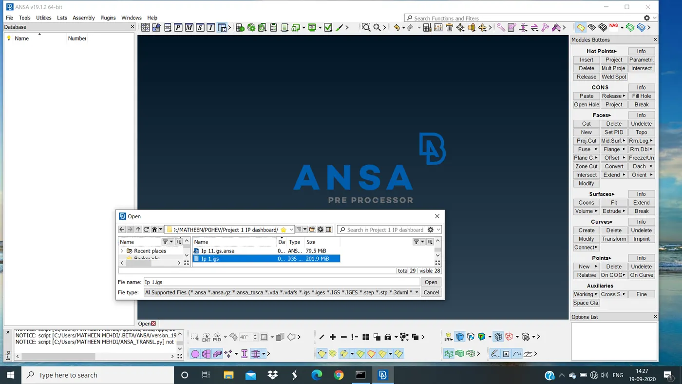
IMPORTING
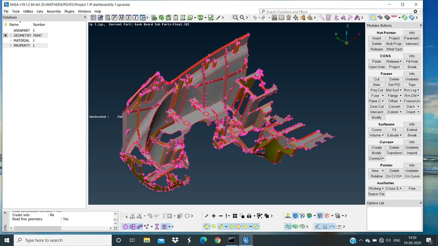
MODEL IMPORTED TO ANSA
STEP 2 :
GEOMETRICAL CLEAN UP
After importing geometry into the ANSA check all the geometrical errors for the given model as shown in fig 2
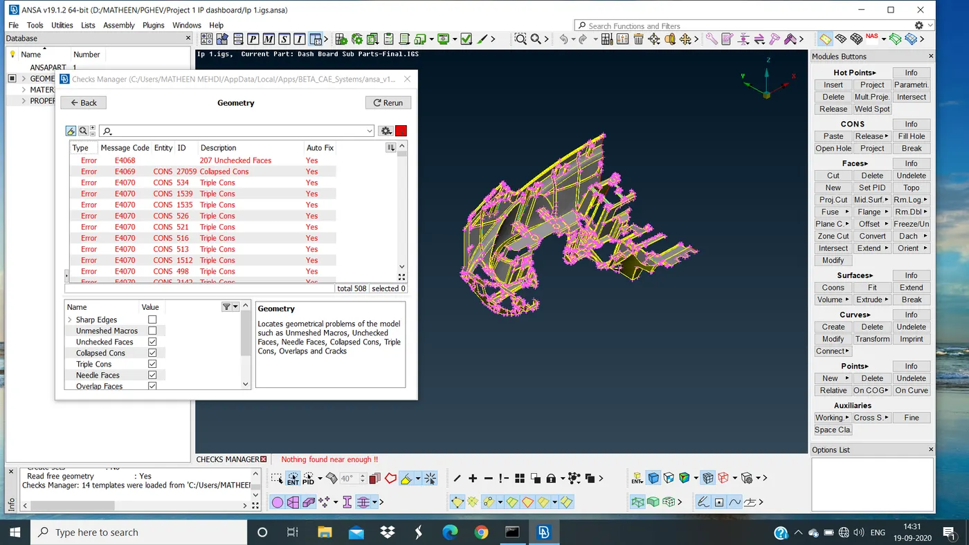
GEOMETRICAL ERRORS
Keeping the feature as a single cons, triple cons, crack needle face checked etc. will see those errors once click to execute button for proceeding further. We need to solve those errors with two options
- By AUTO FIX
- By MANUAL FIX
BY AUTO FIX : select all the errors by selecting CNTRL A press RIGHT CLICK in mouse you will see the fix option then fix those errors by auto-fix some of them triple and others will resolve but still we can see some errors those are fix by manual method.
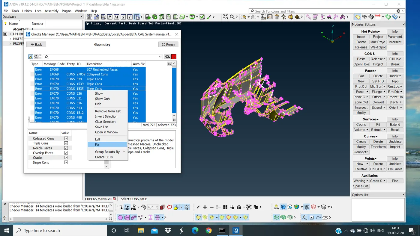
BY AUTO FIX
BY MANUAL METHOD: Manual fixing of these errors. In this method we need one by one approach the error area and fix it by either release cons, deleting face recreating new face again etc. by these we can resolve those errors by manual method.
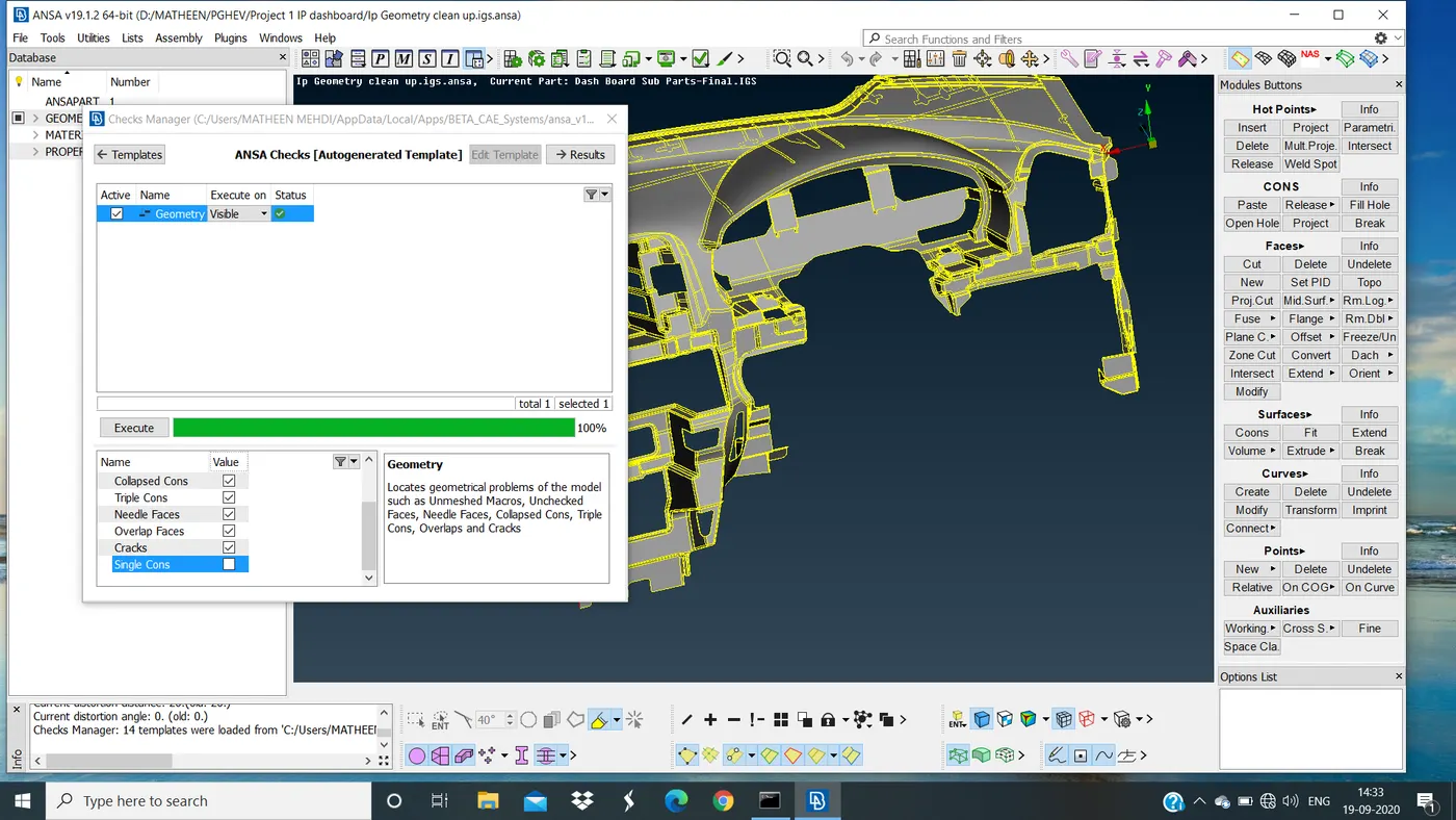
MANUAL FIX ERRORS ARE CLEAN UP
Now the components are error-free proceed for further steps
STEP 3 :
ASSIGN MESH LENGTH
Here we need to assign a given mesh length for that GOTO
MESH MODE >> PERIMETER >> LENGTH .
Set mesh length as 4mm
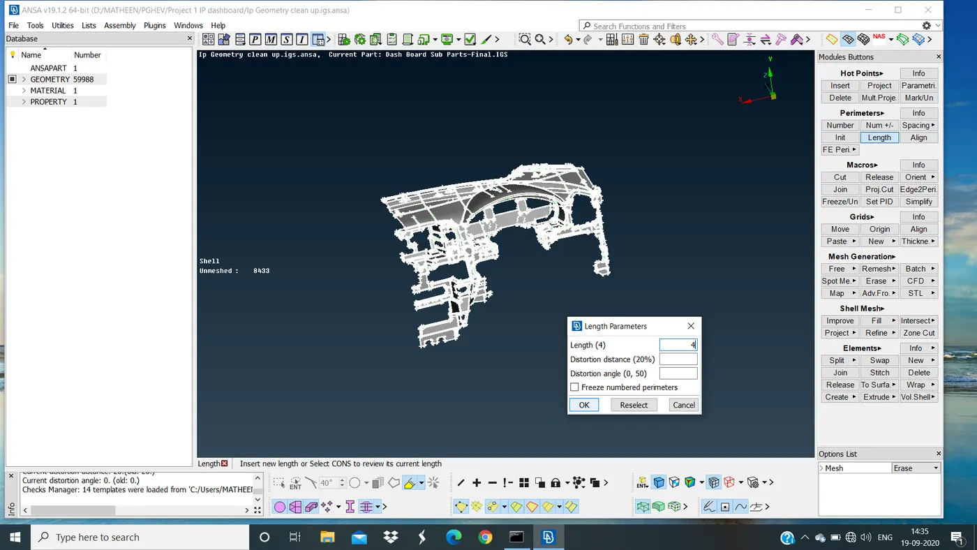
AVERAGE LENGTH
STEP 4 :
MEASUREMENTS AND ORIENTATIONS
Here we have to measure the thickness throughout the component and assure uniform thickness across the entire part. this will help us to take proper mid surface and assign for PID also
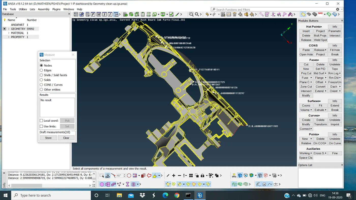
MEASUREMENTS
ORIENTATIONS :
Orientation must be checked working on a model, All components have correct orientation because orientation issue will cause the final time when you merge the model with a complete vehicle
If the orientation is different then we need to check and fix the proper orientation
STEP 5 :
EXTRACTION OF MID SURFACE
there are two ways to extract mid surface
- MANUAL MID SURFACE
- AUTO MID SURFACE
- MANUAL MID SURFACE : This can done by manually selecting the surface and giving an offset to the given model.
- AUTO MID SURFACE : If the geometry is closed then we can go for auto mid surface TOPO >> MIDSURFACE >> SKIN >> OK but here the parent geometry will be deleted you can recover the deleted face by undeleted command.
Here auto mid will not use because since its a plastic component AUTO mid is not extracted at single step.
Here manual mid is done, here are the tools that we use to extract a mid surface middle,offset,middle under curves,extent,project cons etc..
Select offset command from the faces module is used to extract mid of each part.
TOPO << FACES << OFFSET
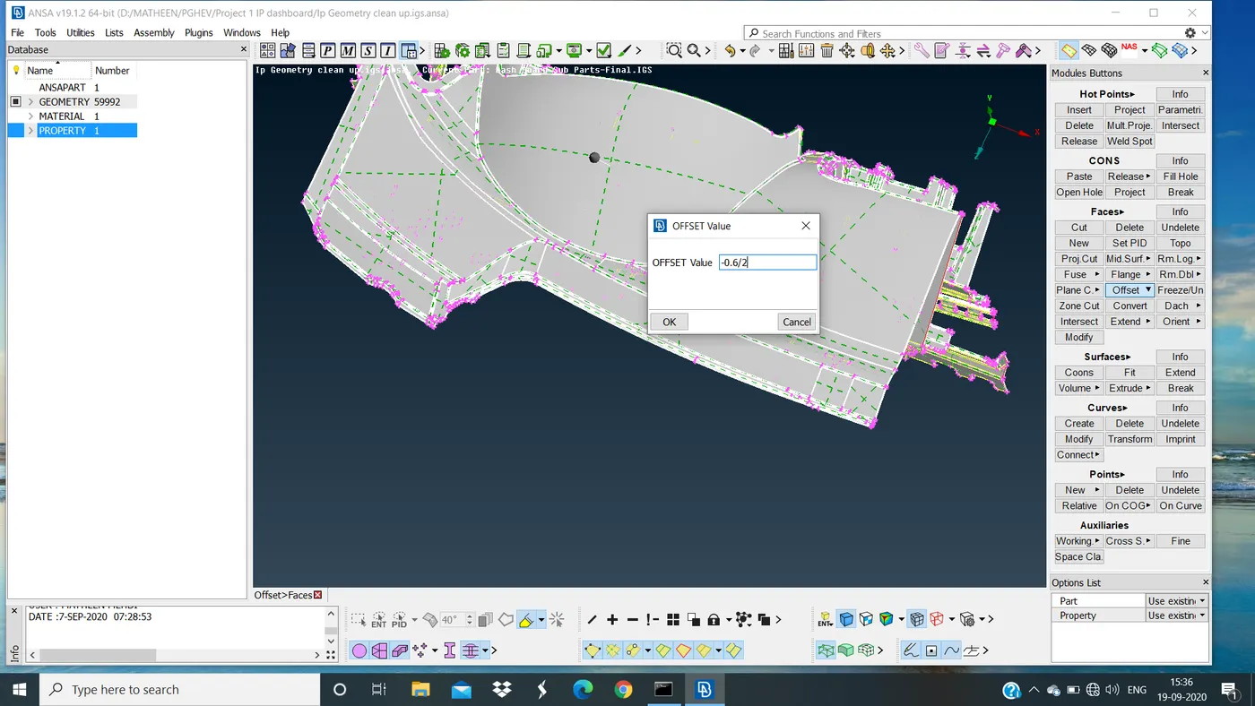
OFFSET COMMAND
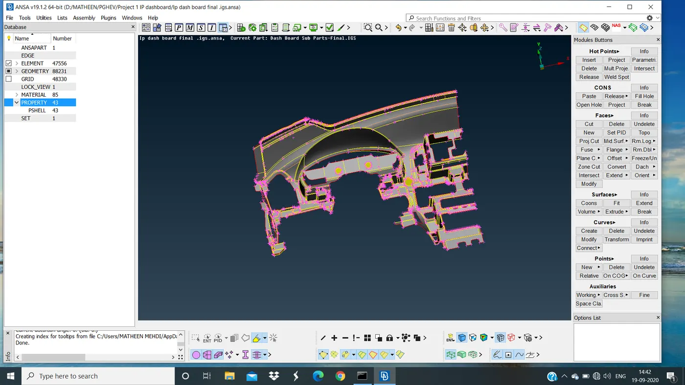
EXTRACTED MID SURFACE OF MAIN BODY
The faces to be extracted by the thickness of each part.
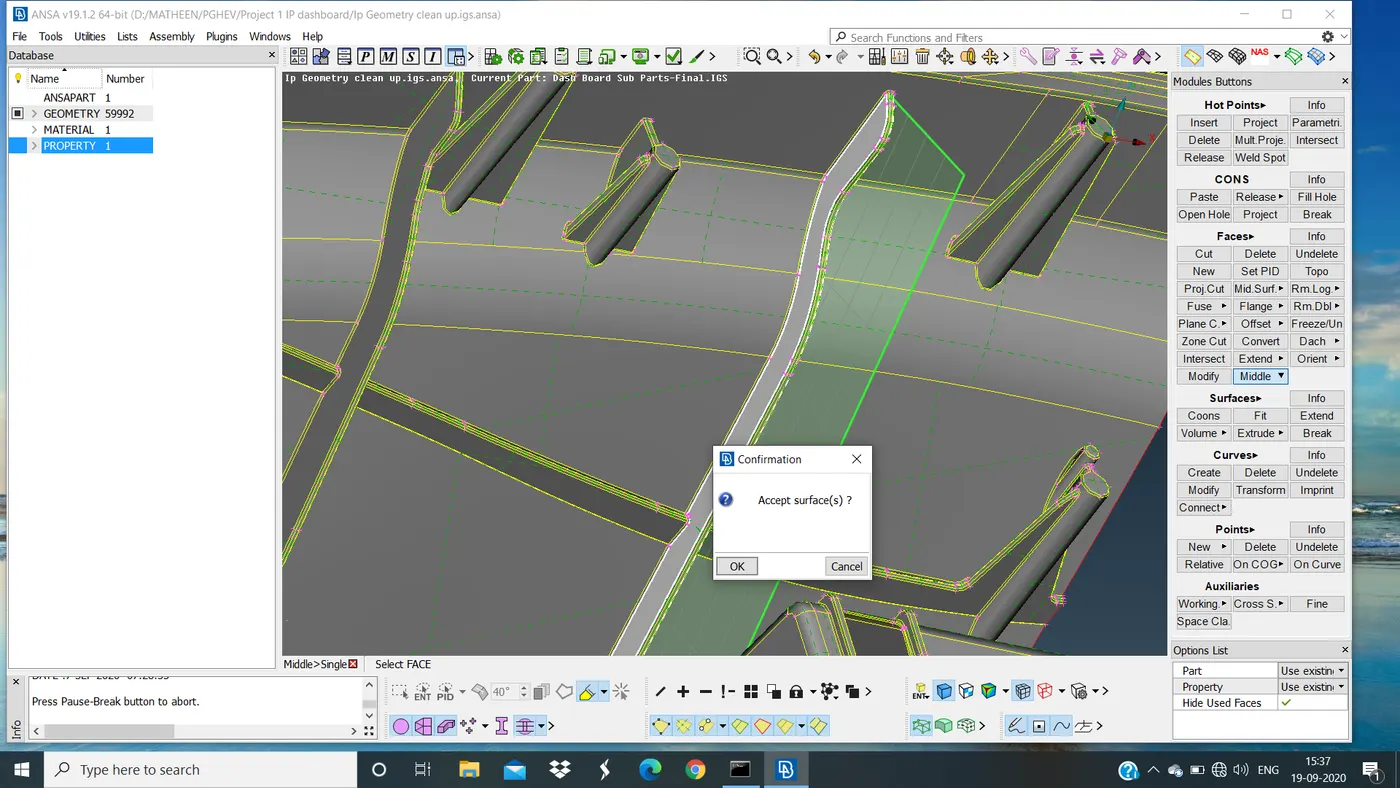
OFFSET USING MIDDLE COMMAND
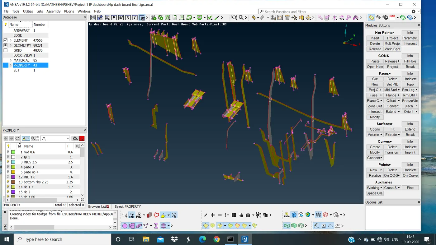
EXTRACTED MID SURFACE OF RIBS
Extend command is used for ribs to extend the mid surface of ribs to mid of main body
TOPO MODE << FACES << EXTEND
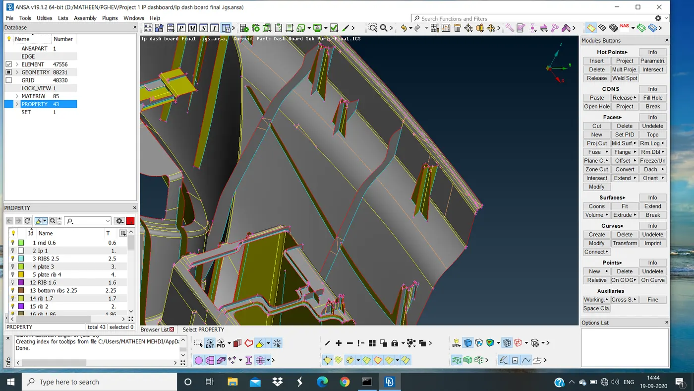
EXTENDED RIBS
Here is a complete mid surface of DASHBOARD
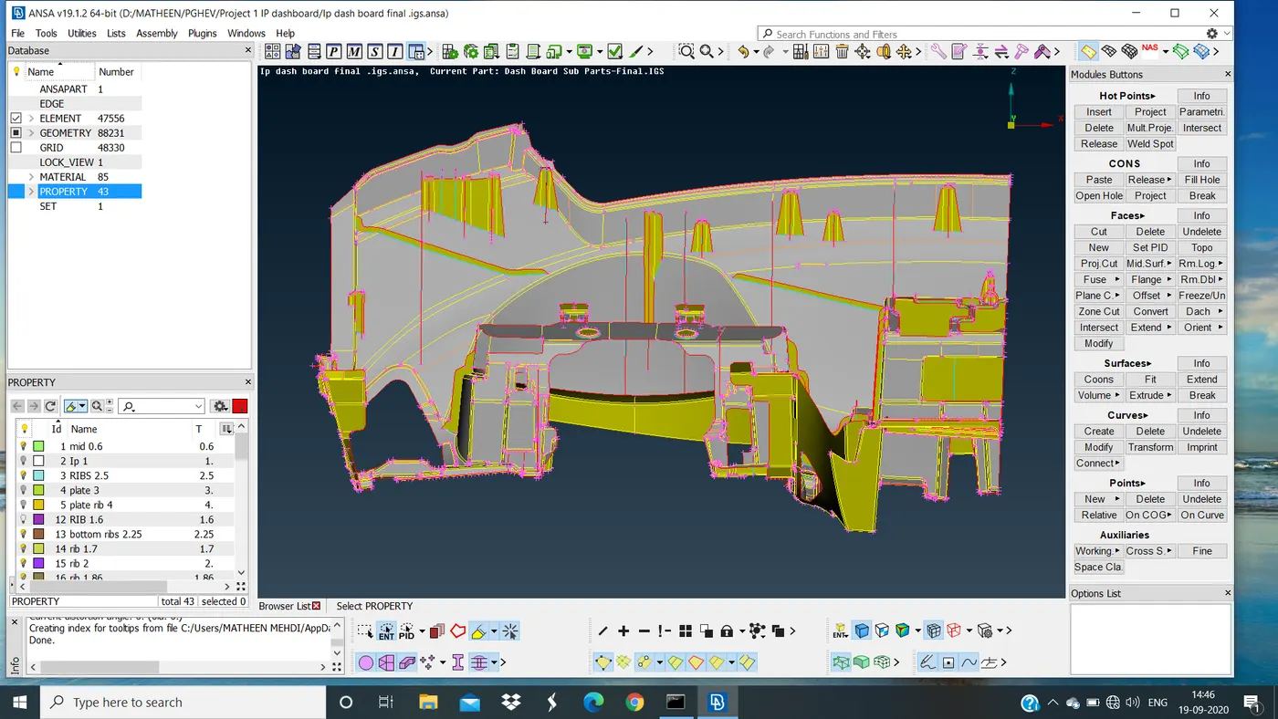
FINAL MID SURFACE OF DASHBOARD
After extraction of the mid surface again we have to check for geometry as there would be any damage face
If yes, means we need to fix those errors
STEP 6 :
DEFEATURING
Here we will defeature those double cons which would fail for minimum length here the minimum length is 2mm
Suppose the distance between two cons is less than the minimum length then we have to defeature that line because it will cause the minimum length errors after meshing, So we need to defeature those
GOTO TOPO MODE << FACES << CUT
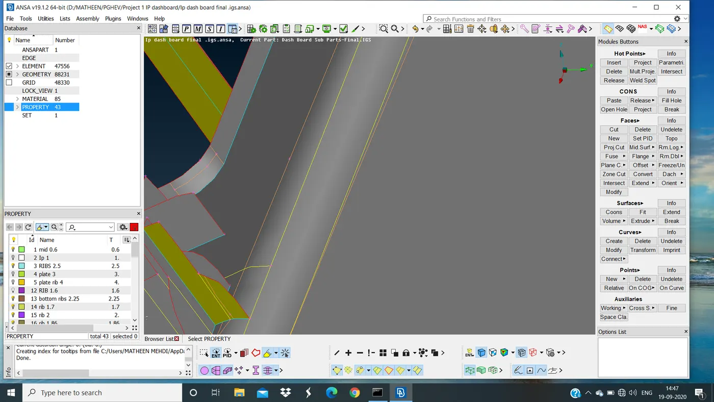
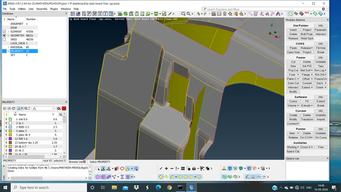
DEFEATURING
STEP 7 :
MESHING
Before going to mesh we just talk about quality criteria
We can say that result quality is directly proportional to the element quality. the parameters like skewness, angle, jacobian, warping, minimum length, etc.
Before going to mesh assign mesh parameter and quality criteria as per the given
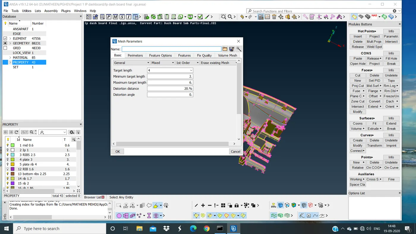
MESH PARAMETER
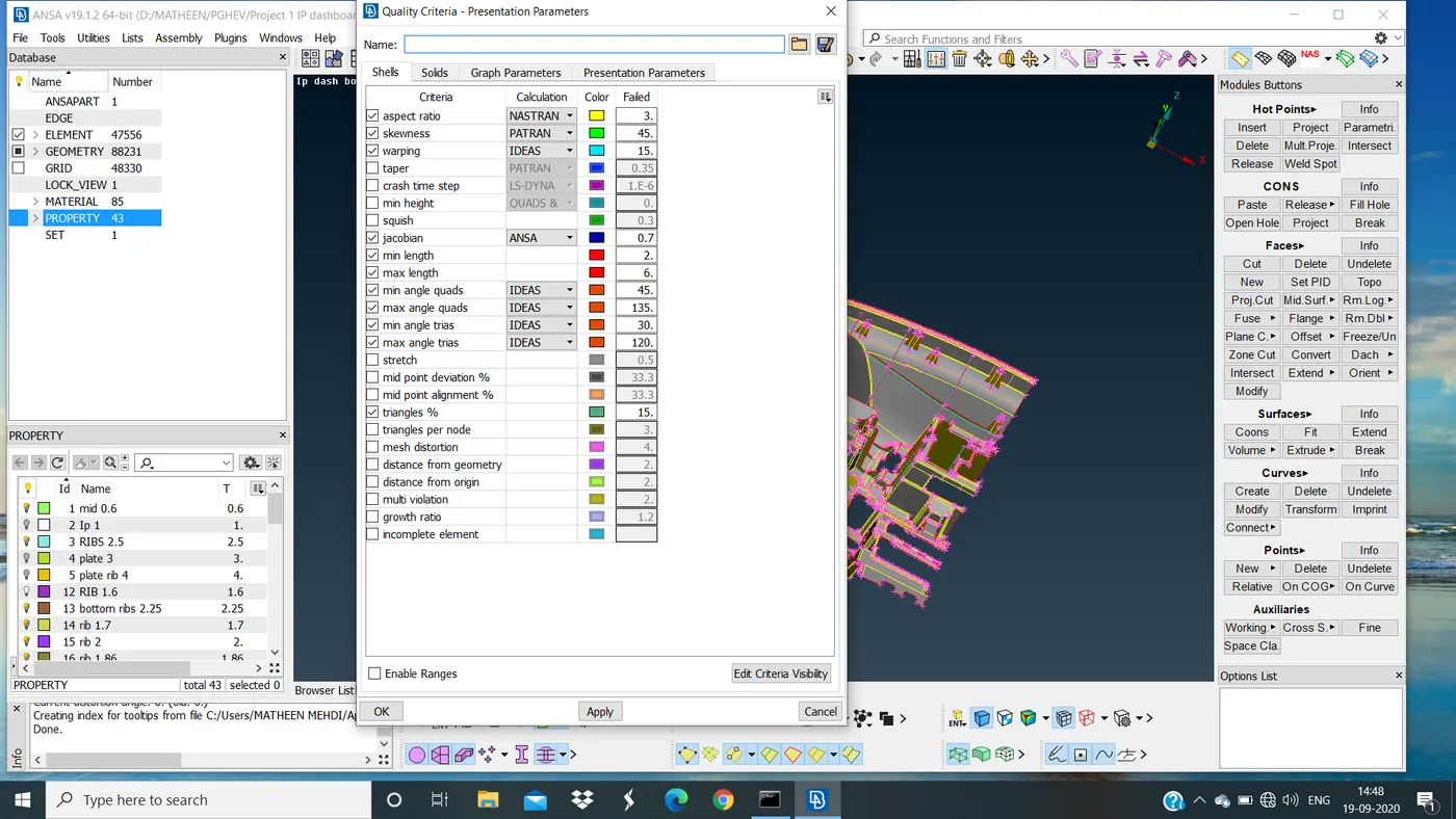
QUALITY CRITERIA
Now mesh the component before selecting any mesh algorithm set element length
GOTO MESH MODE << PERIMETER << 4mm
Perform mesh with best mesh algorithm it will give best mesh flow create a mesh and element type is chosen as mixed
MESH MODE << MESH GENERATION << BEST.
Reduced trias and rotating quads by using split, swap, smooth, reconstruction, etc..using these commands will reduce trais and rotating quads
MESH MODE << SHELL MESH << RECONSTRUCTION .
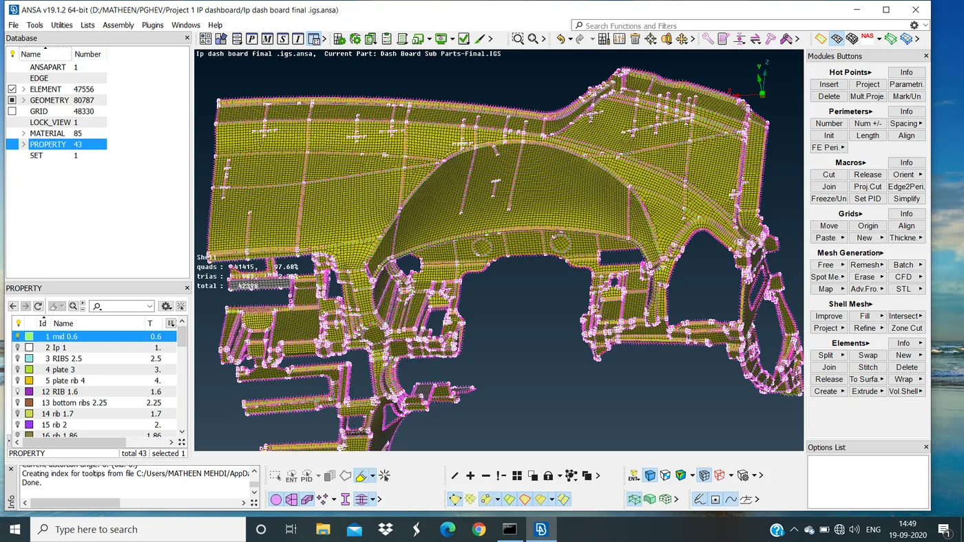
MESHING OF MAIN BODY
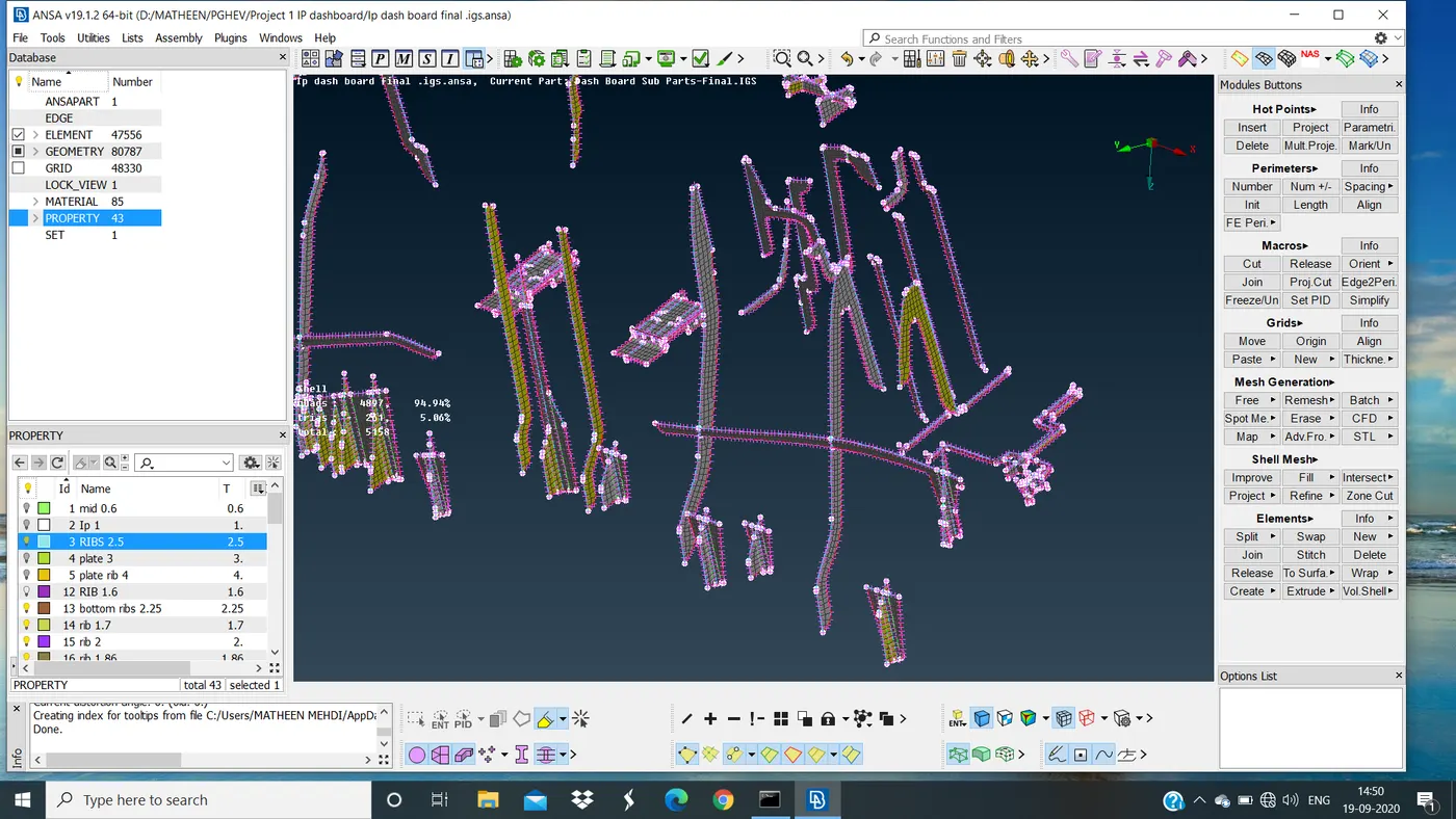
MESHING OF RIBS
For better mesh flow we need to follow some rules :
- Opposite tria's are avoided.
- Flat surface trai's should be avoided by merging them using split.
- Avoid trai's near to hole region.
- Hole feature should be in even-numbered.
- Avoid tria's at the perimeter line.
- Avoid zig-zag mesh flow.
- Avoid rotating quads.
- Divides the large surface into small parts using cut for meshing.
- Defeature the area which is going to fail the quality criteria.
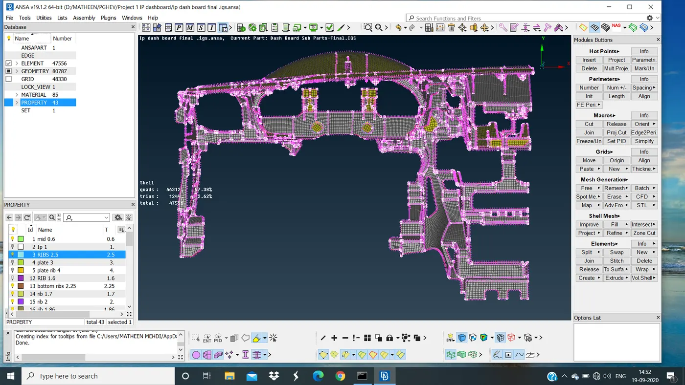
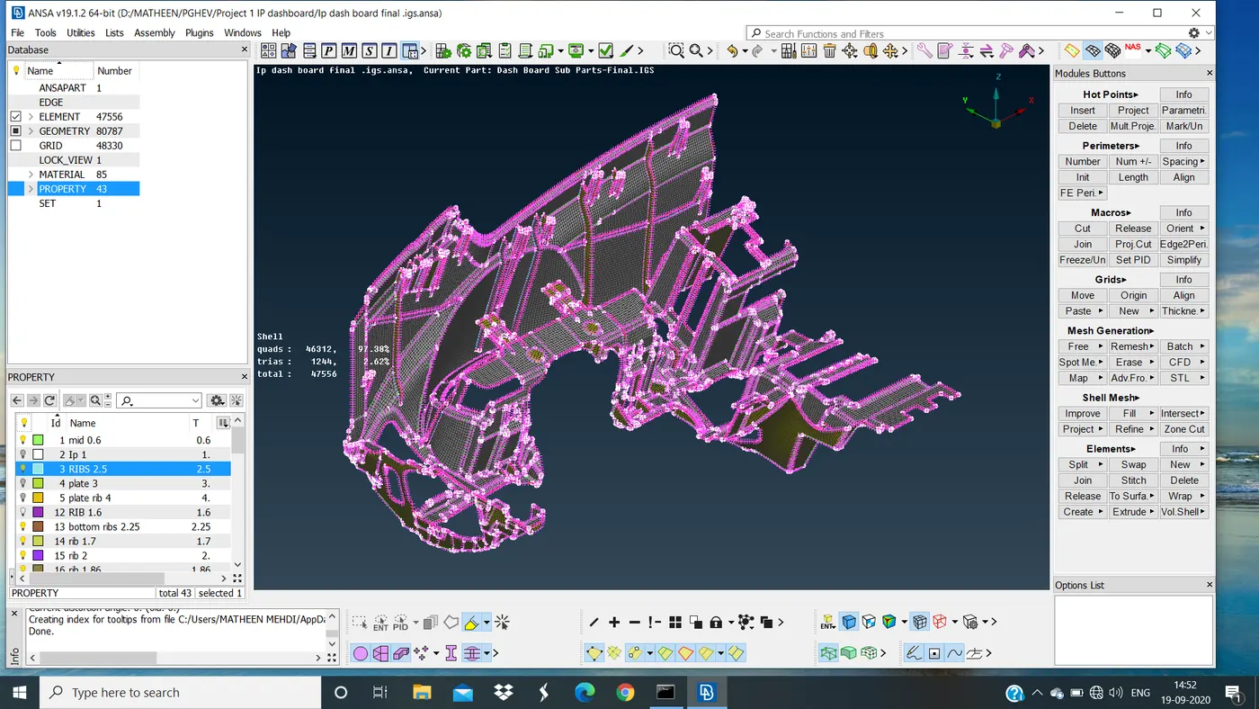
FINAL MESH OF DASHBOARD
Capturing cylinderical pillar feature with square shape
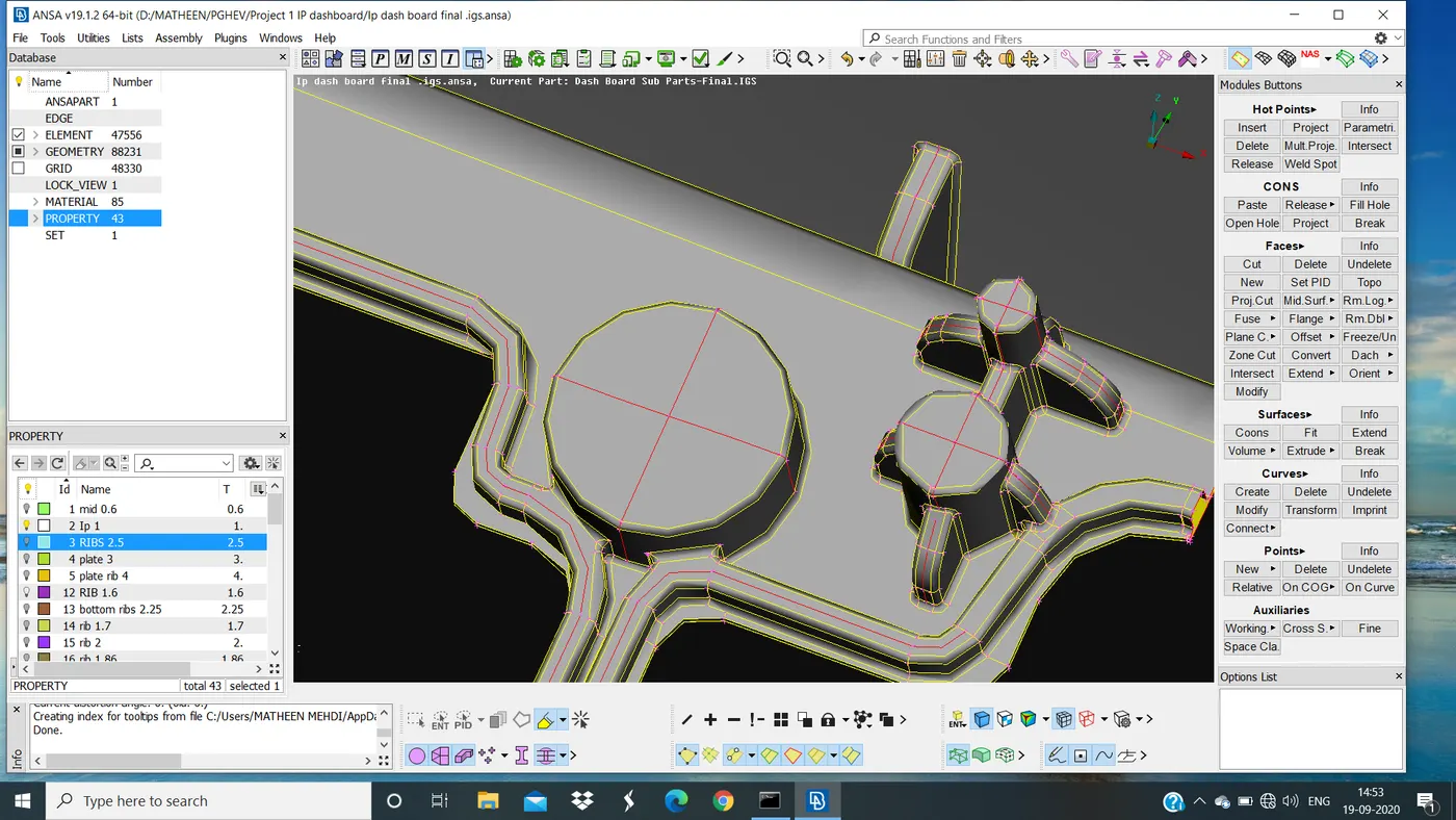
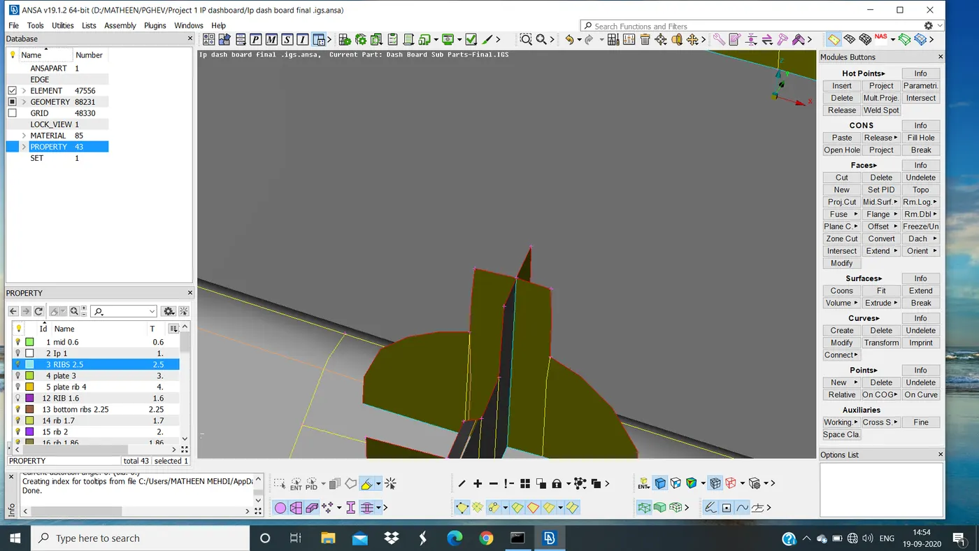
CAPTURING CYLINDRICAL FEATURE WITH THIS SHAPE
STEP 8 :
ASSIGN NEW PID AS PER THICKNESS
After meshing is done we have to assign a new PID as per the thickness
Select macro under mesh mode set new PID
Select the area where have to create a new PID and created it as per thickness.
MESH MODE << NEW PID << OK
The thickness of each part are entered and their type is chosen as P.SHELL
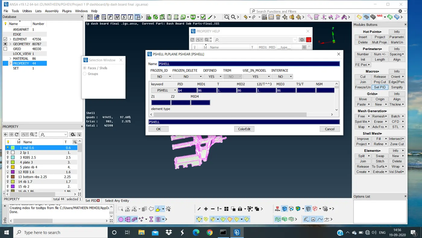
ASSIGN NEW PID
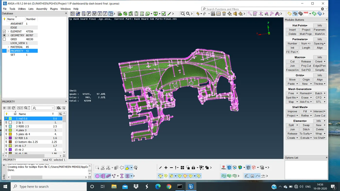
ASSIGNING NEW PID OF MAIN BODY OD DASHBOARD
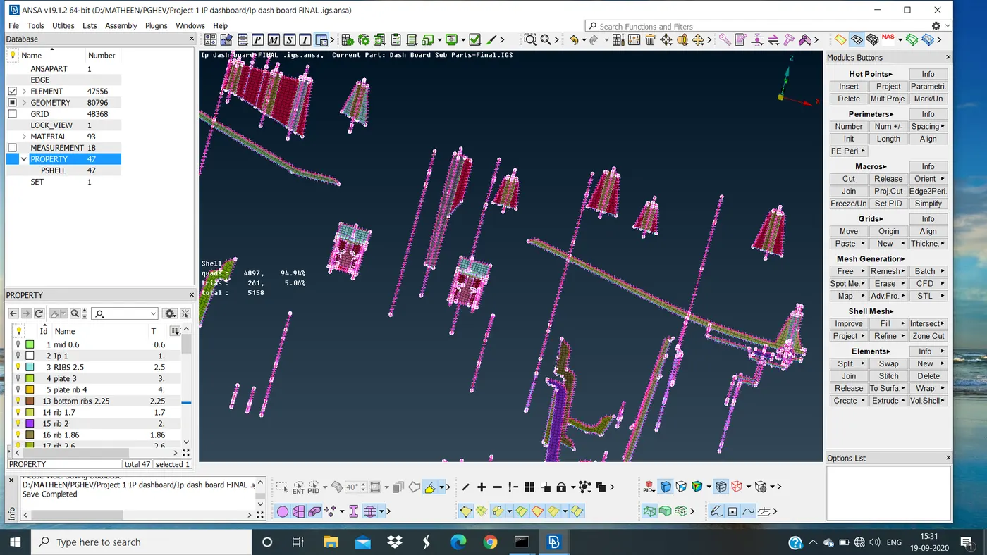
ASSIGNING NEW PID FOR RIBS
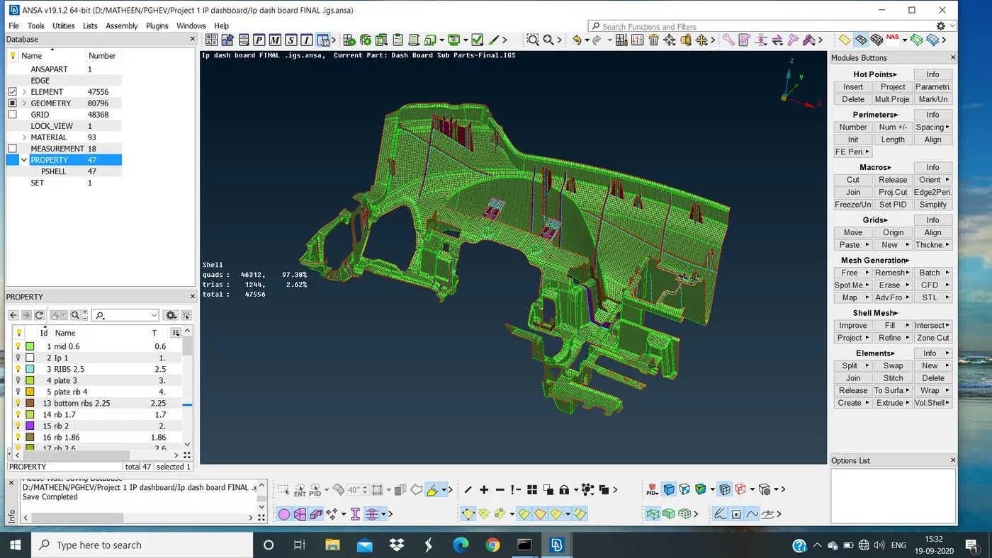
FINAL PID OF DASHBOARD
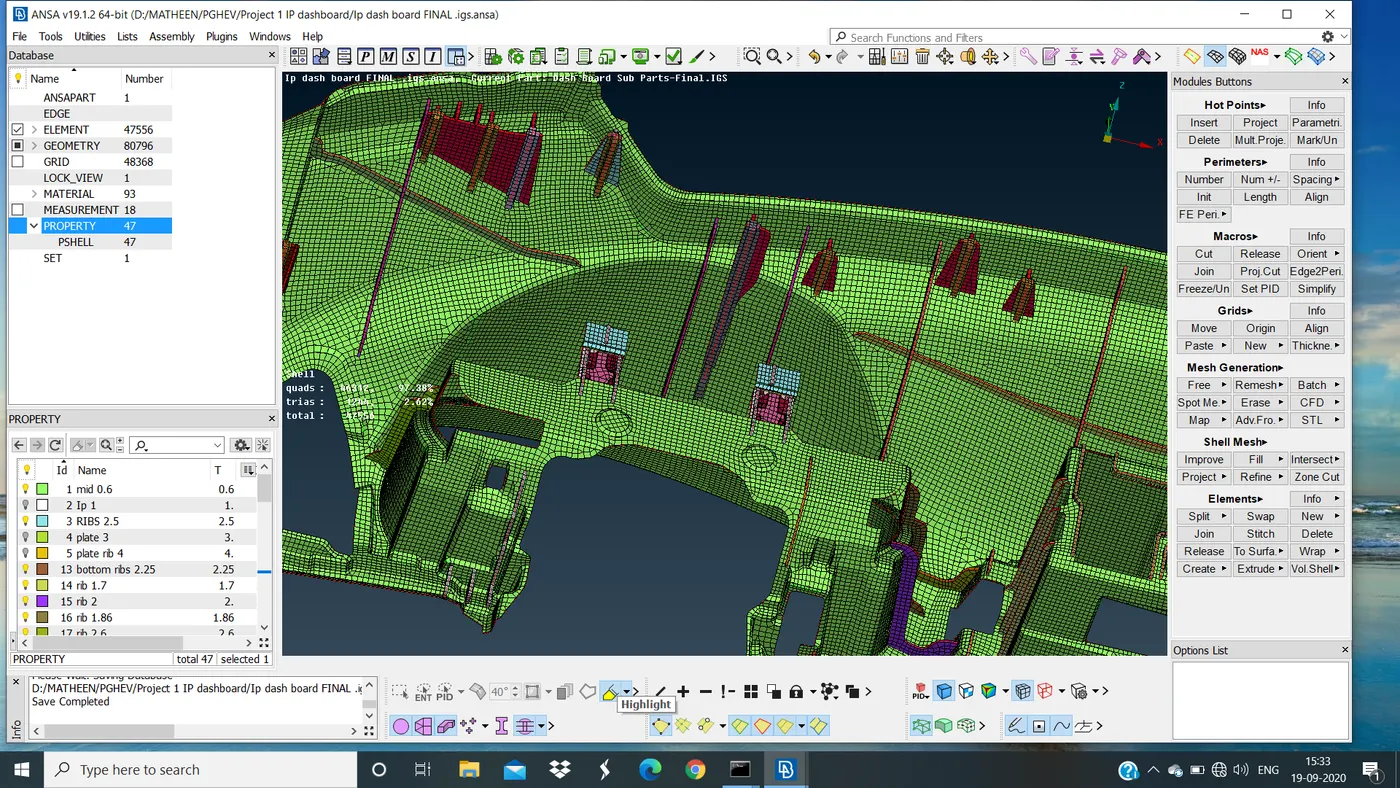
RESULT : All parts are successfully meshed as per the given quality criteria and enable shell as solid as shown in fig below
LEARNING OUTCOMES :
- Learned how to import CAD model to ANSA.
- Learned how to fix geometrical errors.
- Learned how to create mid-surface for given complex geometry.
- Learned how to mesh with best mesh algorithm.
- Learned how to fix rotating quad and tria's.
- Learned how to assign new PID as per thickness.
CONCLUSION :
In the above dashboard model successfully generate mid surface and mesh the model as per the given criteria the total element 47556 out of which 1244 are tria elements and 46312 are quads which makes 2.62% of tria percentage which is good and the flow wise of mesh is also achieved well.