Project 1
Aim: Route the Wiring harness on V16 Engine and Prepare flatten view drawing in CATIA V5.
Objective:
- The main purpose of this report is to understand the basic fundamentals of the Electrical Wiring Harness and also define the electrical connncetion to the connector and connnecter clip using Electrical Part Design Workbench in Catia V5.
- Application of all Packaging rules.
- Apply Protection coverings as required.
- Create a Flatten view of the Harness Assembly.
The list components that are needed and provided are as follows:
- c-1563689-1:
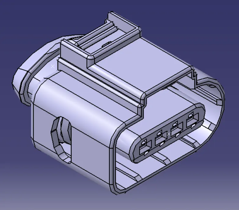
The cad part file is available and downloaded fron TE website.
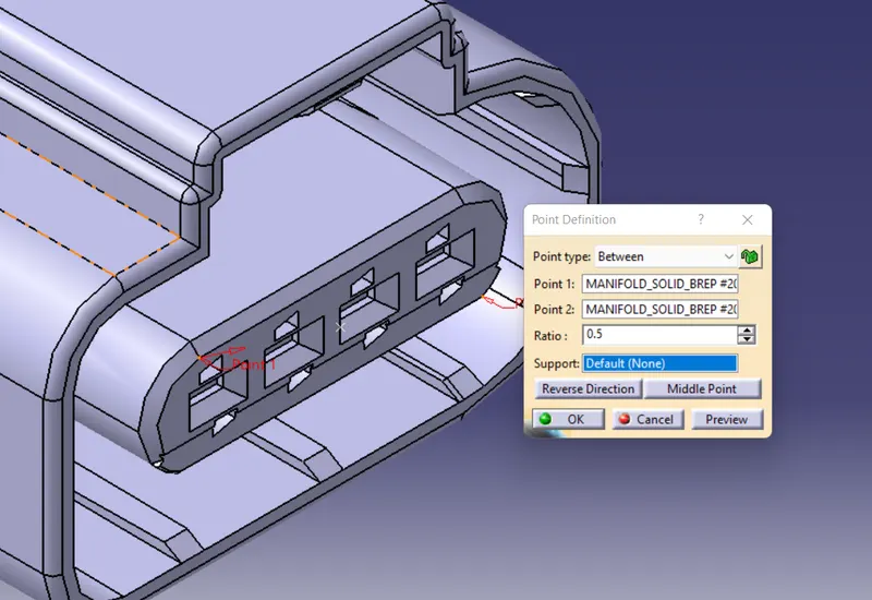
Now the file is opened in the Part design workbench. Now the point on the either side of the connector is created by selection between points as shown below.
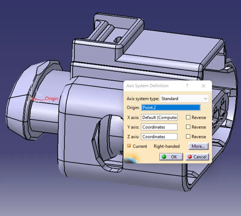
The axis is created as shown in above figure.
Now the model is transferred to electrical part design. The model is designed as connector (terminals 4). Now the one end point of the connector is defined with a bundle connection point and Connector connection point.
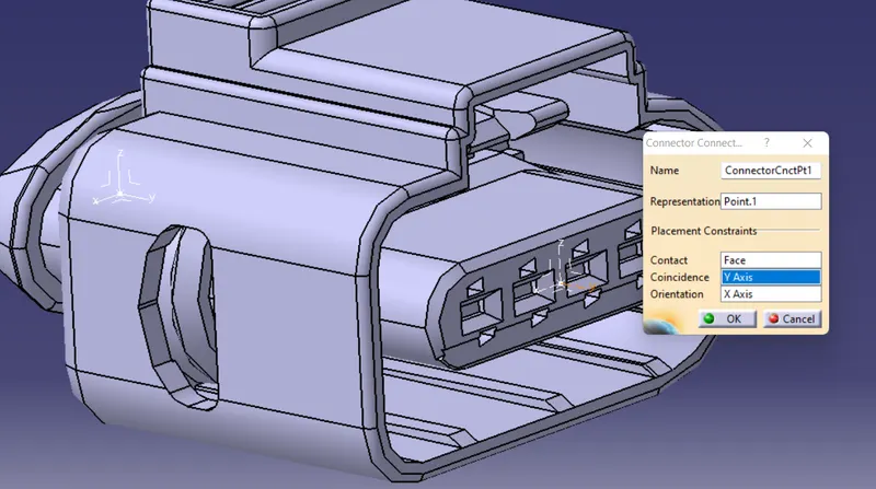
Now save the file.
Same procedure is followed to the other connectors
- C-282080_1:
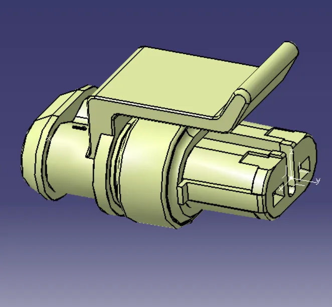
- c-776438-4-d:
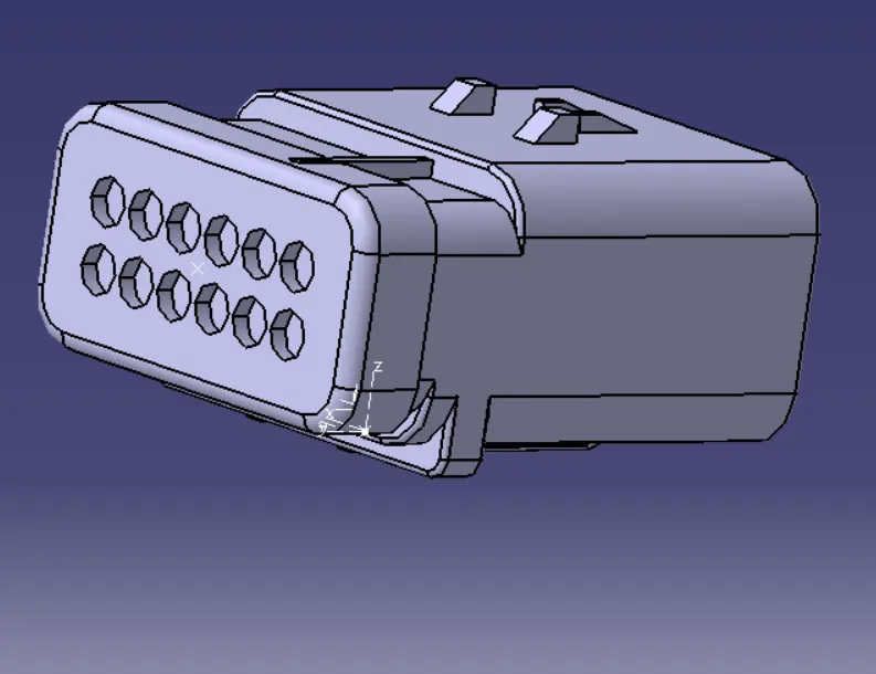
- C-1924487-2:
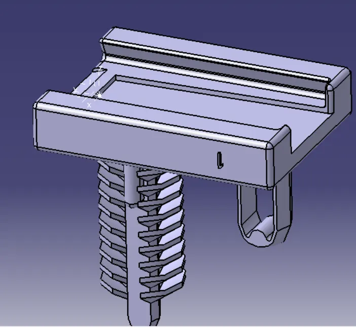
In the above part the type of connection is cavity connection point. So we have to define the component with the define option  and then proceed to add cavity point.
- Channel Bottom:
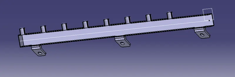
- P Clamp:
A P clamp or also known as pipe clamp is a type of clamp often employed in woodworking, piping or cabinet shops.
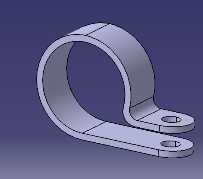
Steps:
- First the part file is downloaded from the required catalogue and saved.
- Now for the clamps here a total of 3 planes has to be created ( one on the either side and other the base plane.
- Now a point is created at on side by selecting the circular profile as shown in below figure and activating the circle center arc.
- Similary, the point on th other side of the clamp is created.
- Now, the planes are created one by one selecting the points and making sure that paralled through point is selected as shown below. The end flat surface is selected as the reference
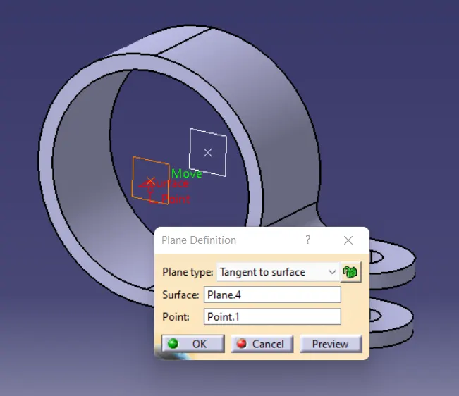
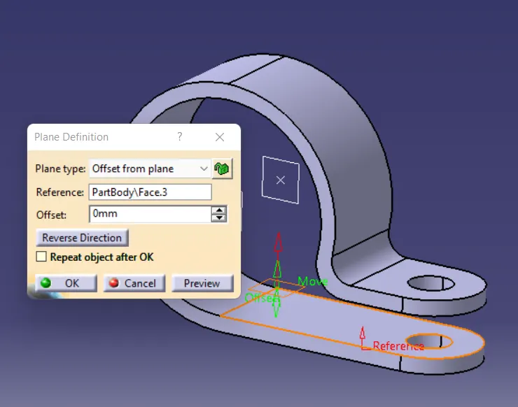
- Once both the planes on the either side are cerated, next base plane is created by selecting offset from surface by 2mm and selecting the flat face as shown in above figures.
- Next step is to define the electrical supports.
- The workbench is changed to Electrical part design.
- Now click define support
 and select the clamp part body. Then select point 1 and respective as first plane defination, then other plane and base plane.
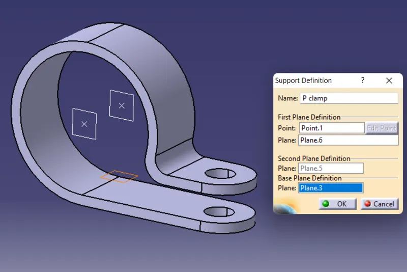
Now all the supports are porvided to the p clamp and the file is saved.
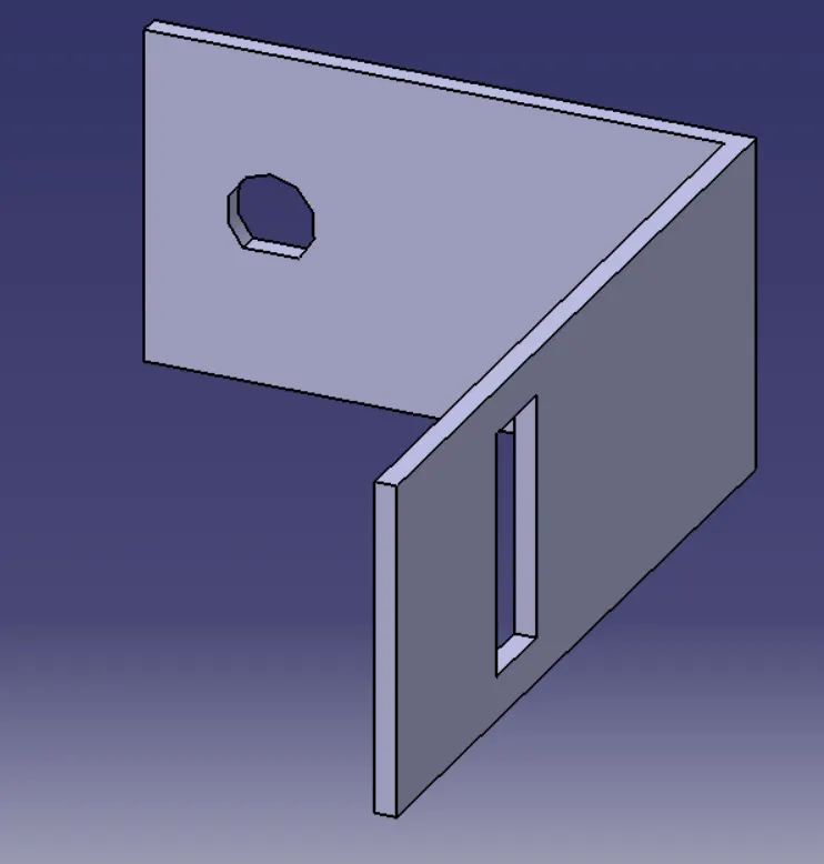
- L clip:
- Engine:
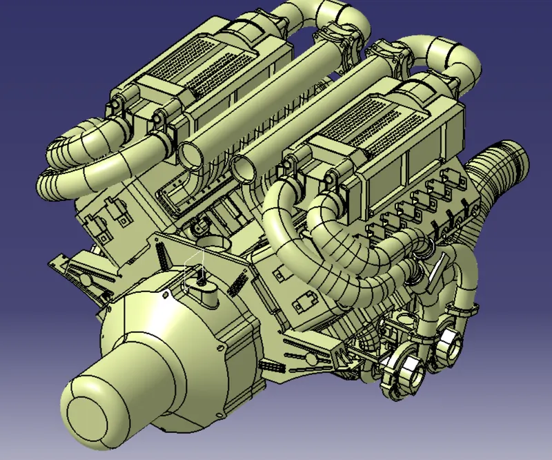
Next step id to arrange all the components like connectors, clips, channels to their respective places and orientation on the engine model.
The various tools such as Manipulation  , Snap
  , Smart move
  and symmetry
  are used to place, move and oreint the connectors to the places shown in below images.
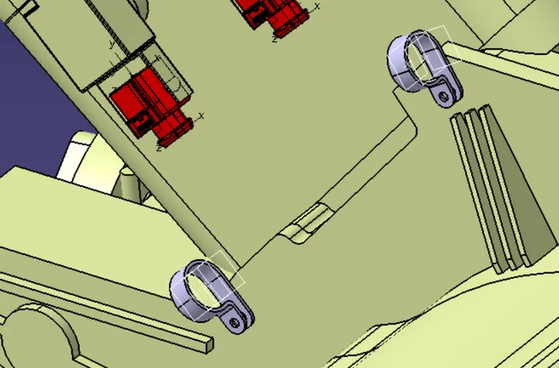
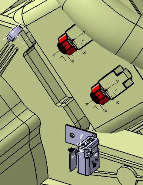
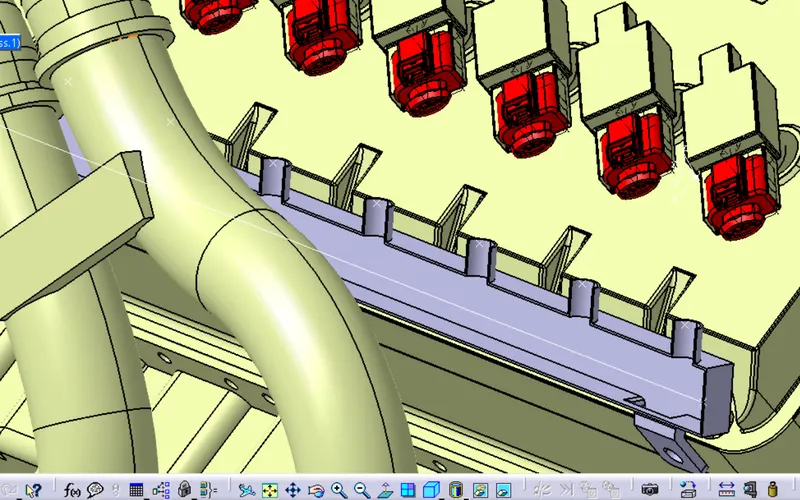
Next step is to create the bundle segments.
First we have to create a geometrical bundle in the electical harness assemble and then proceed with the next step.
Now the route is defined as required using clicking multibranchable document  and then clicking branch defination
 .
.
Appropriate diameter is taken and under route defination, the two connectors between which the branch has to be create are selected adn click OK.
Now the branch is created between the connectors as shown below.
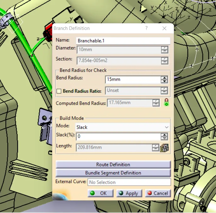
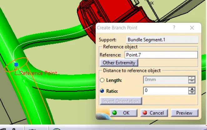
Now for the other branches to be created, we have to create a branch point by clicking Add branch point 
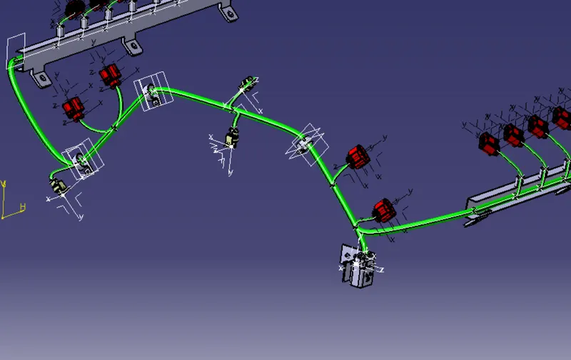
Once all the braches are created, the branches will look as shown below:
Next step is to add the protective covering over the routre bundles. Select protective covering option  and then the in the catalogue option we have to select the catologue where we have saved all the corrugated tubes.
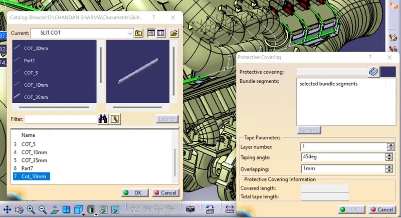
Similar procedure is carried out for all the branches.
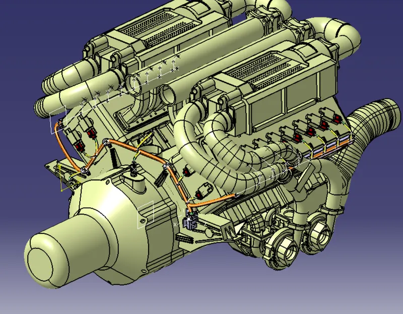
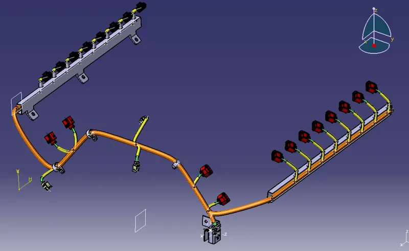
Finally the complete routing harness is done as shown below:
- Now open new product file and select Eletrical harness flattening workbench.
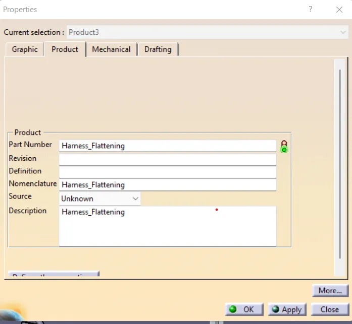
- Rename the product file name as required as shown below.
- Now adjust both the file window equally as shown below:
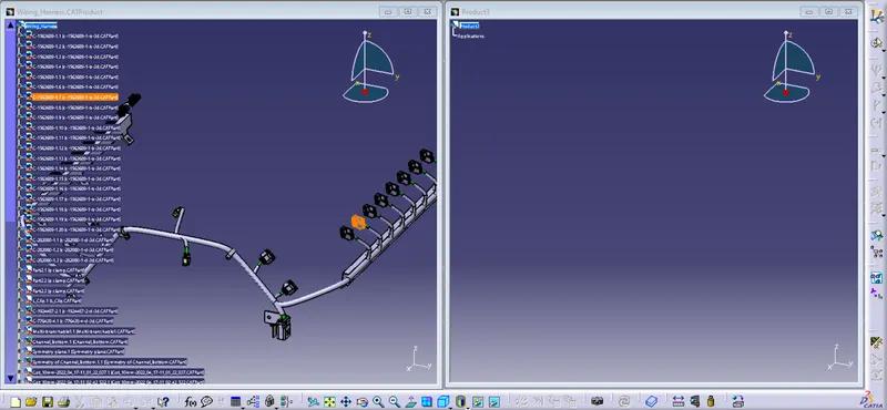
- Bring the harness assemble in the flattening product file using extract option
 .
. - After the assmebly is extracted the file type is changed to .EHF (which stands for electrical harness assembly flattening) as shown in below image
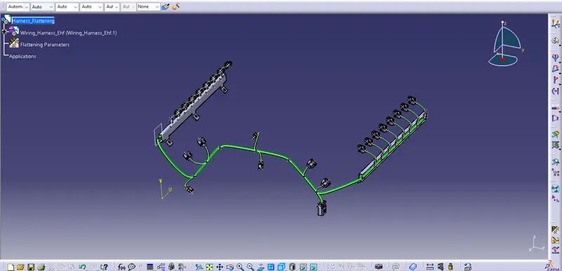
(Now we have to flatten the assemby)
- Select flatten option
 .
. - Then select all the electrical bundles which has to be flatten as shown below.
- One can also select one main bundle branch and then click Select all branches in the flatten window.
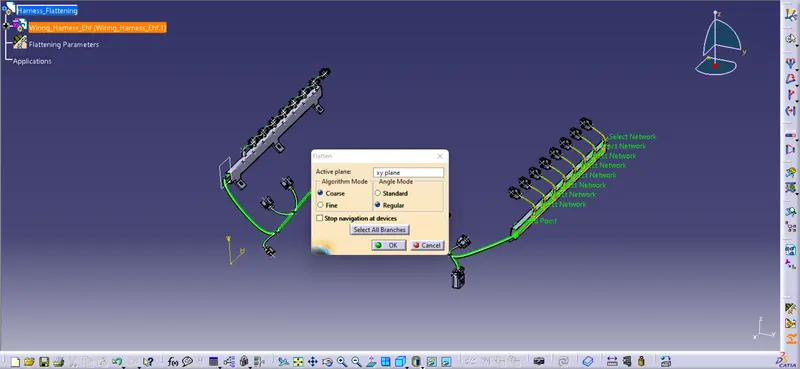
- After flattening the bundles will look as below.
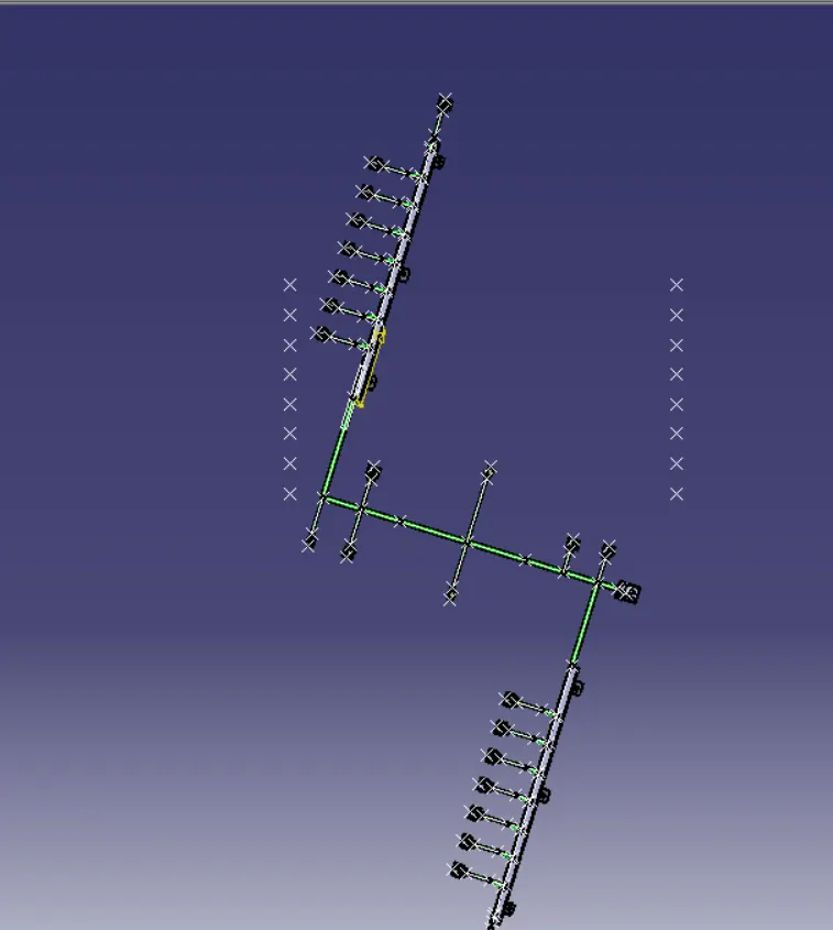
Here we can select either XY plane as the flattening plane or any respective flat surface of the any one connector.
Since here the flattening is done on there positions automatically, we can directly go to the drwing part.
But this wont happen always. When the branches are not orient as per required flattening, we have to adjust the branches such that all the branches are their in their respective places and orientation.
Let see how to adjust the orientation of the branches if required.
- To adjust the branch angle click on rotate option
 .
. - Now select the branch to be rotated.
- Give the angle as required to bring the branch on the respective place.
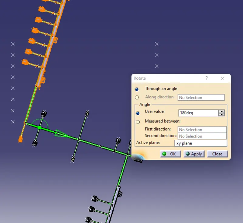
- This step can be performed for all the other sub - branches if required.
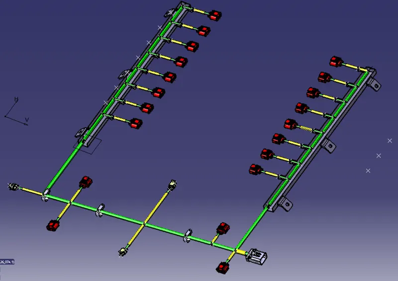
- Since we have flatten and oriented the assemble properly to their respective places and orientation as required as shown in above figure, next step is to create the drawing view.
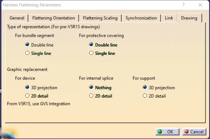
- Before that change the parameter as shown below
- Open new drawing file and set the following parameters as shown in figure.
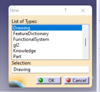
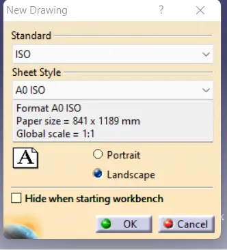
- First save the drawing file as Flattening_Drawing.
- Adjust both the windows side by side for better unerstanding.
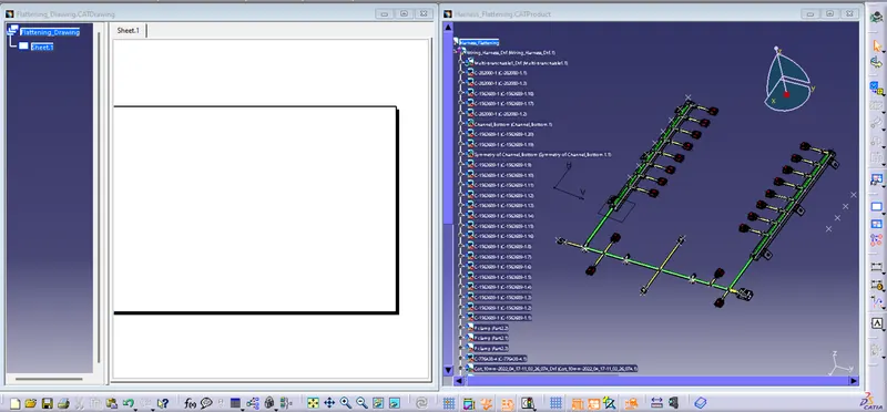
- Click front view option
 in the drawing file and then select any one flatten surface of the assembly.
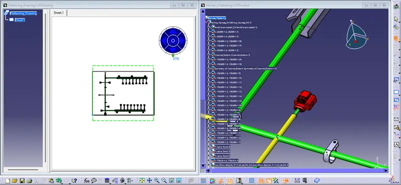
- Adjust the view with the help of the manipulation tool
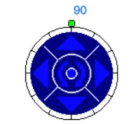 as required..
 - Once the view is oriented, click the drawing sheet to complete.
- Now we have to change some parameters so that we get the drawing as required.
- Right click on the view and select properties and properties window will open.
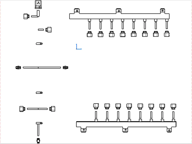
- Under view tab click on the 3D wireframe option and make it visible always.
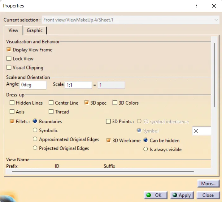
- Click OK.
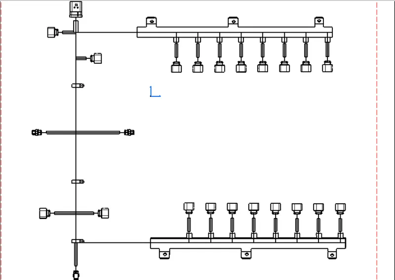
Thus the flattening drawing created.
Conclusion:
Hence all the connectors and supports are electrically defined ans assembled along the engine component to their respective places.
The budle segment with appropriate size is created between the connectors and the clamps.
The protective covering is appliead to the bundle segment with respective size selected from the catalogue.
The Flattened view and the flattened drawing of the Electrical harness assemlby is created. The bundle protectioncs are shown in different visual comapred to the bundle branches.