Project 1
PROJECT - 1
***Attatching the google drive link below for complete files regarding Project - 1 due to exceeded 20MB file limit size and only the final outputs in a separate folder in the browse option. ***
AIM = Route the Wiring harness on Given Engine and Prepare flattened view drawing in CATIA V5. Application of all Packaging rules, Industry best practices studied in this course shall be demonstrated in design. Apply Protection coverings as required. Available connector 3D data can be used, or you can download the connectors from www.te.com Prepare & Submit all necessary reports like clearance, Clipping/Clamping selection, Harness fixing requirements, Harness continuity, and Assumptions if any along with CATIA 3D data.
REPORT
Download the required Engine and Connectors file from the source and define them electrically by using the electrical part design work bench by following below steps.
- Get into the mechanical part workbench to create required geometrical parameters.
- Create connector connection point and bundle connection point on all the required CAD parts.
- Create axis system on the connector connection point such a way that the Y coordinate facing normal to the connector face, X coordinate facing towards the locking mechanism and Z coordinate facing to the top.
- Create cavity connection point for connectors having the cavity for mounting clips
- Using the geometrical parameters created,
- Define part as electrical connector.
- Define bundle connection point.
- Define connector connection point.
- Define cavity connection point.
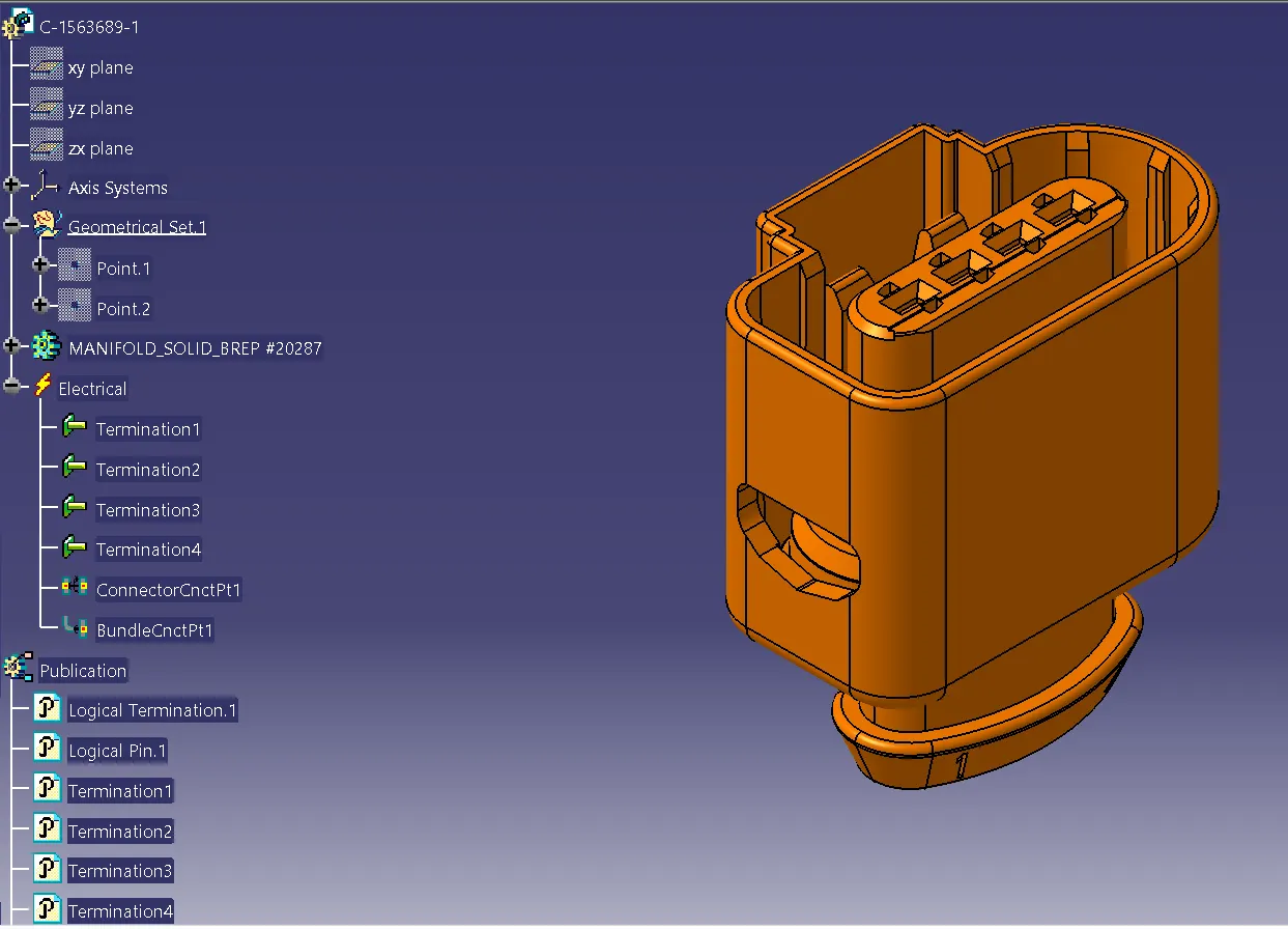
C-1563689-1
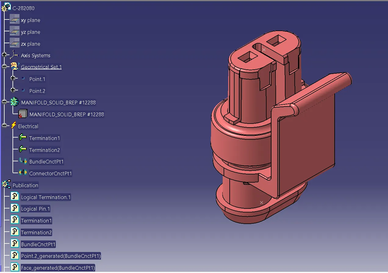
C-282080
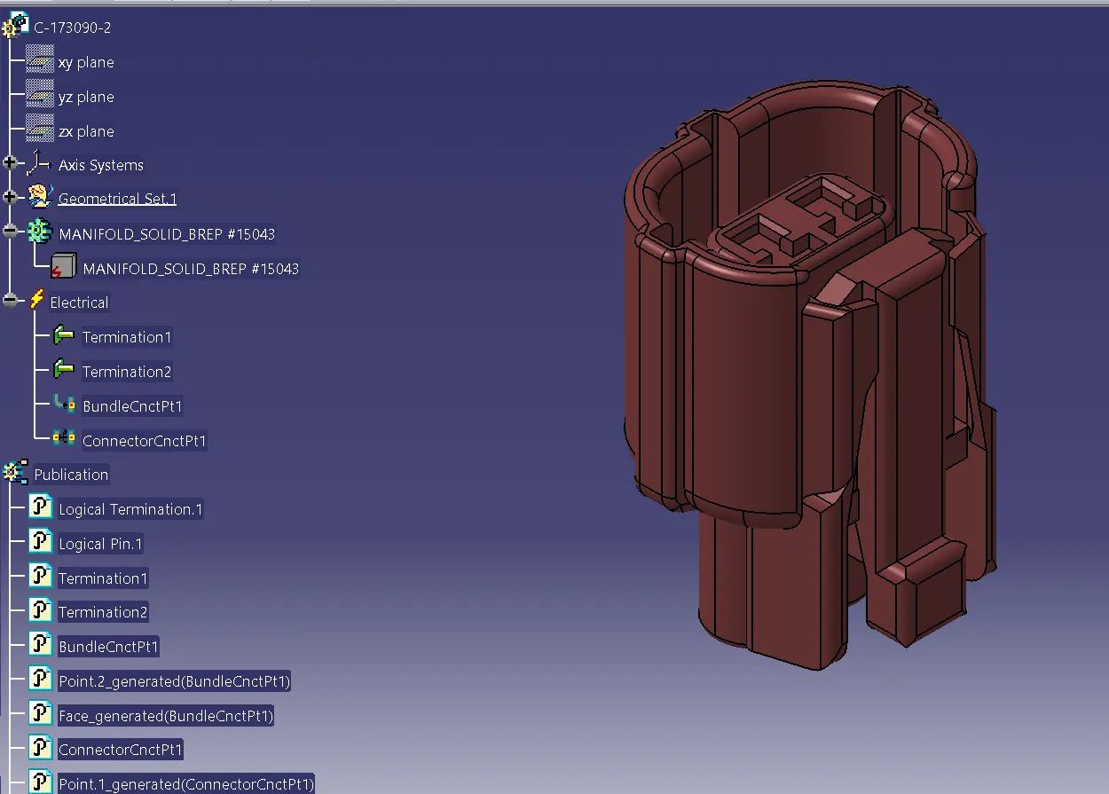
C-173090-2
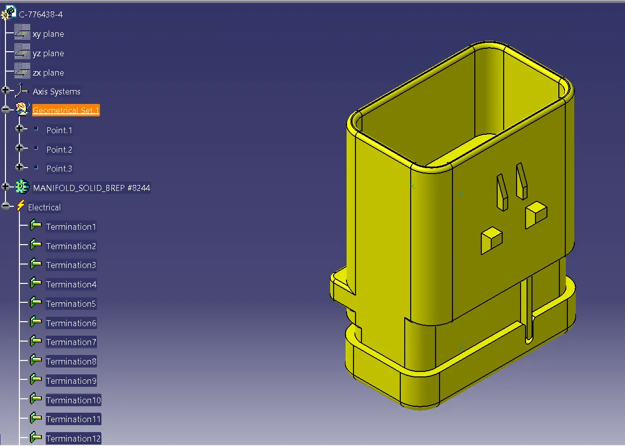
C-776438-4
C-1924487-2
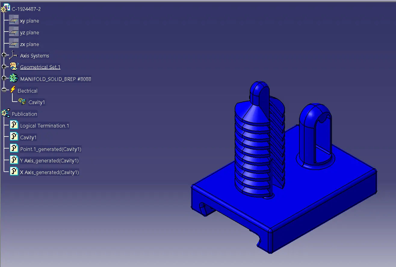
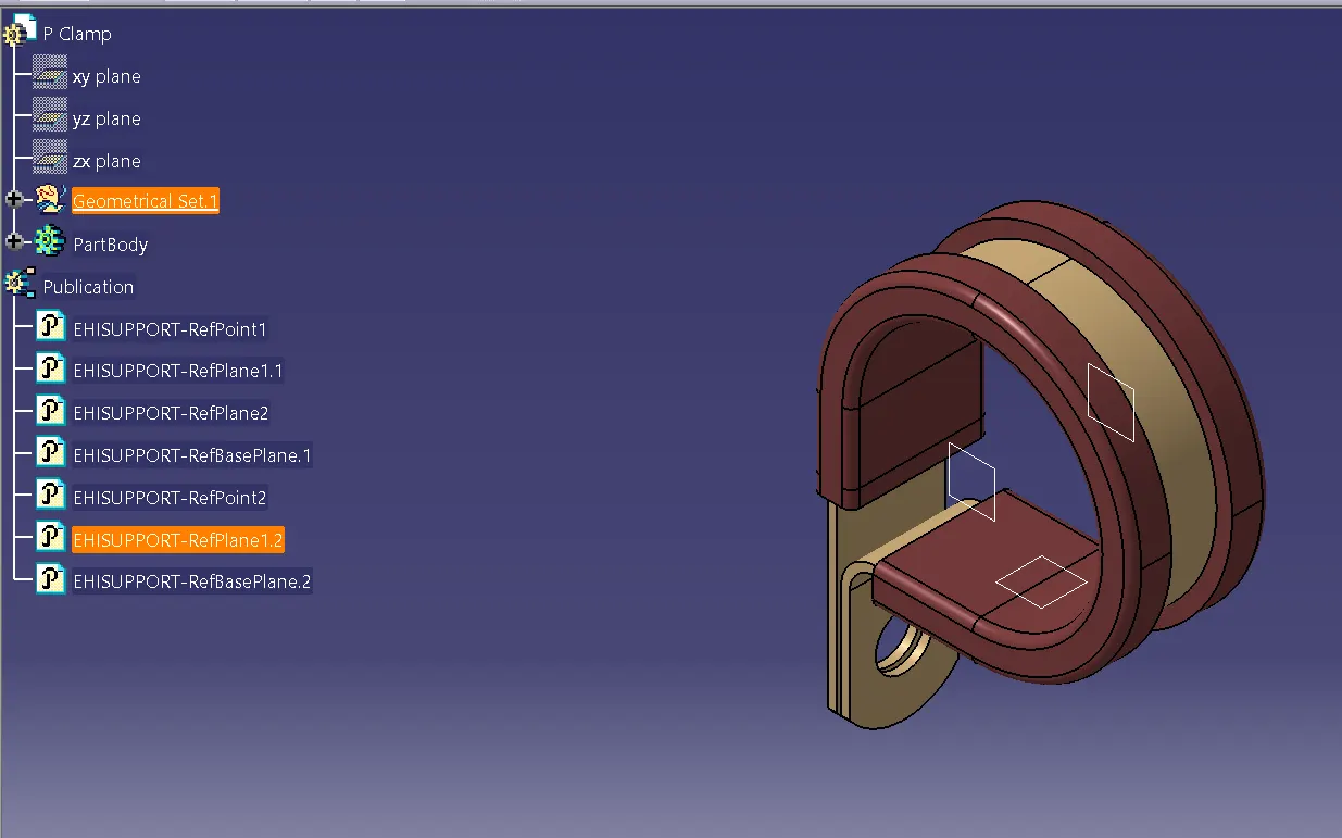
P Clamp
MOUNTING FEATURES
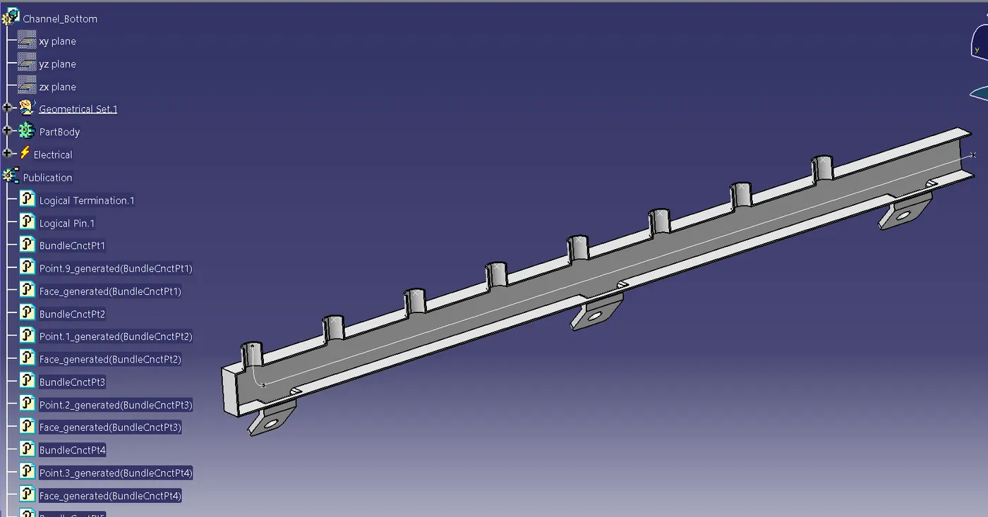
- Channel Bottom
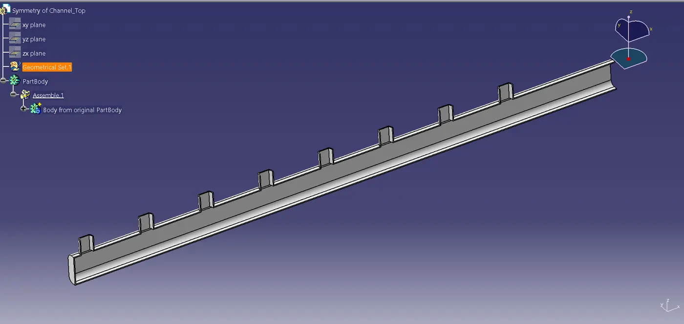
- Channel Top
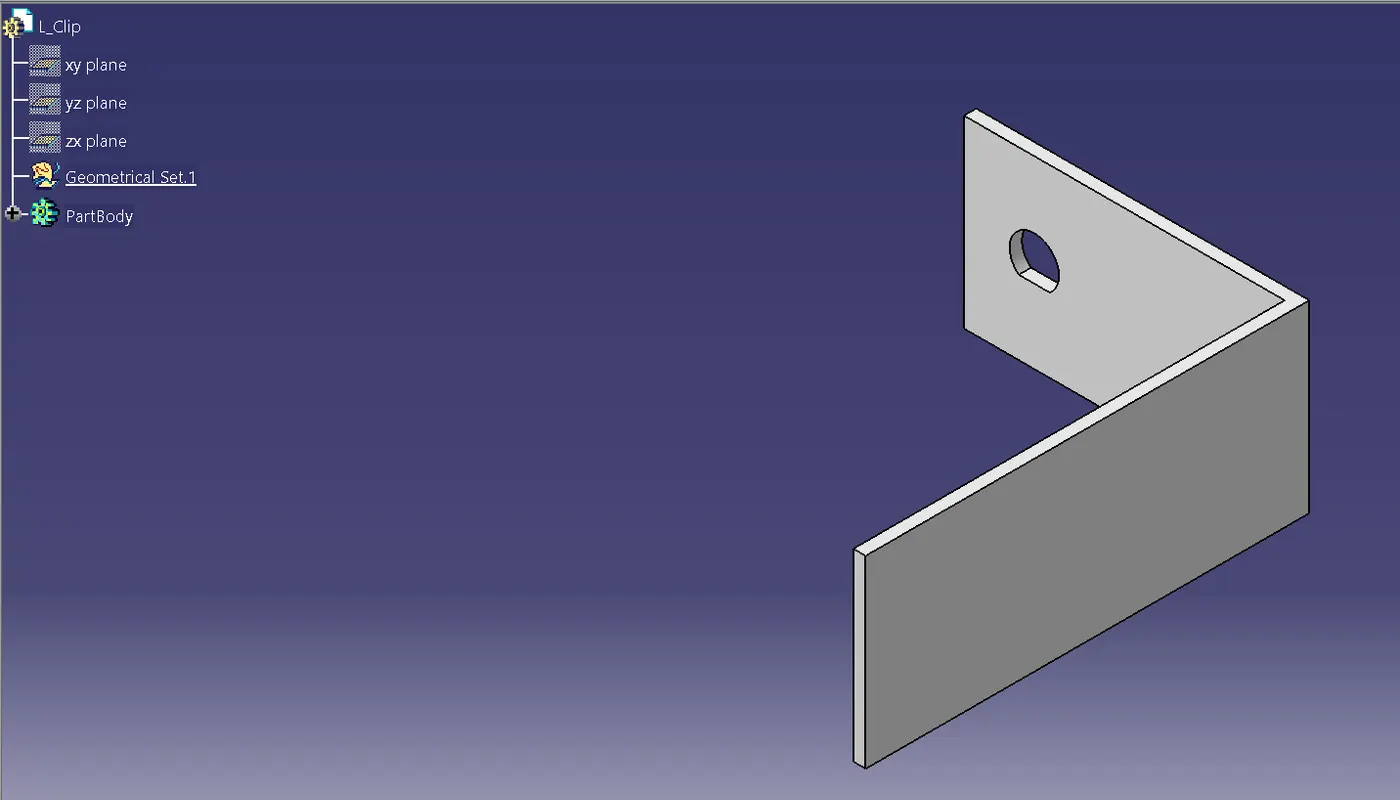
- Sheet Metal Bracket
Harness routing and packaging
- The downloaded and electrically defined connectors are added into the geometrical bundle and properly positioned onto the fuel injectors, camshaft sensors, vehicle speed sensor, neutral position sensor and engine coolant sensor with manipulation tool, compass, smart move, snap commands.
- Aligned the interconnection connector in the Sheet Metal Bracket with support of provided firr tree clip.
- P - Clamp can be placed at appropriate location and ensure clearance management.
- The p – Clamps can be mounted to the existing holes provided on the Engine block in which the screws to tighten the Engine block.
- Place the channels in required locations to provide harness to connectors. Use of Plastic Guiding channels are recommended to meet the clearance in critical areas if it is difficult to achieve by use of clamps.
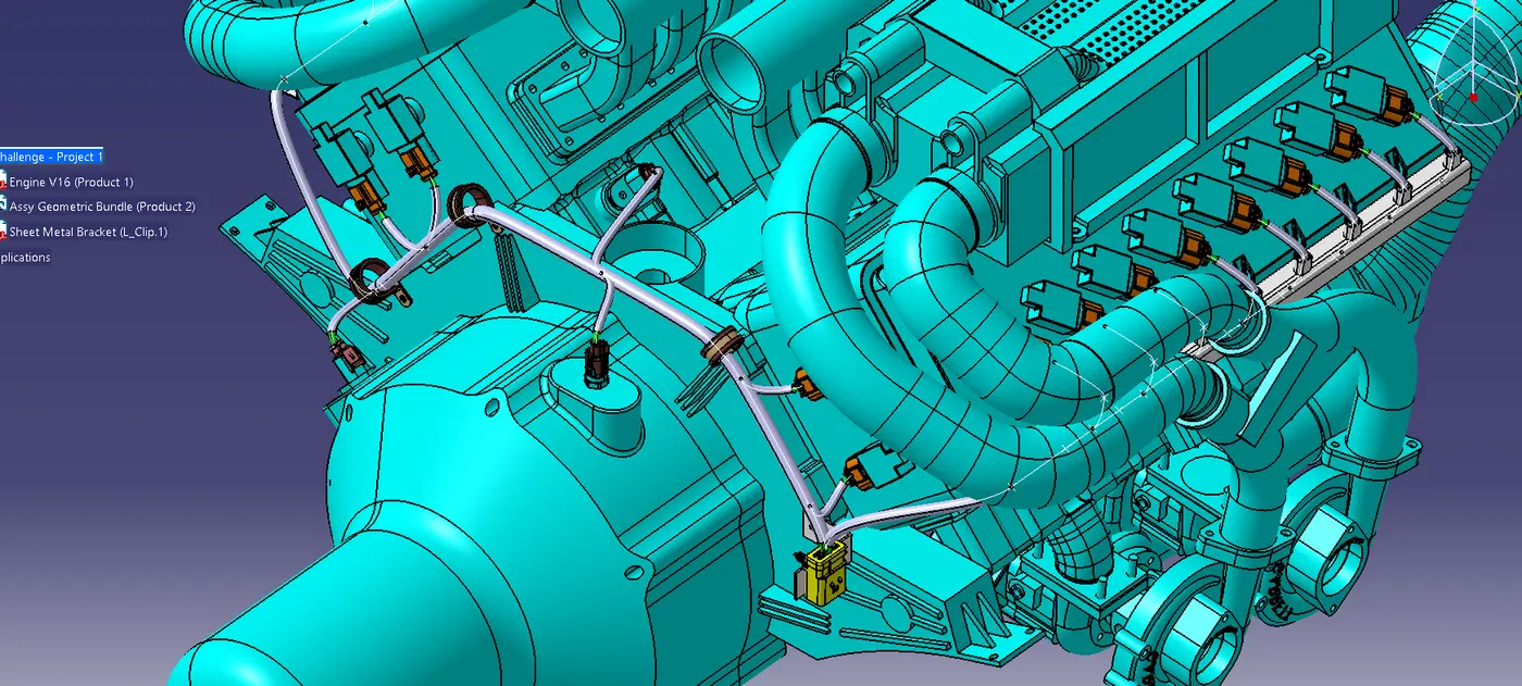
- After defining and aligning of connectors and sensors, select the multi-branchable command to do bundle routing.
- The routing starts from the inter connection connector and passes through P-Clamps to connectors and guiding channels to connectors along the sides of V16 Engine.
- To route the wiring harness in channel use external curve option and click on the line created, add branch points, provide proper bend radius and slack % to avoid the additional stress to connection.
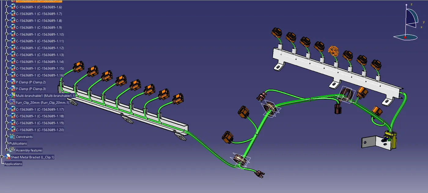
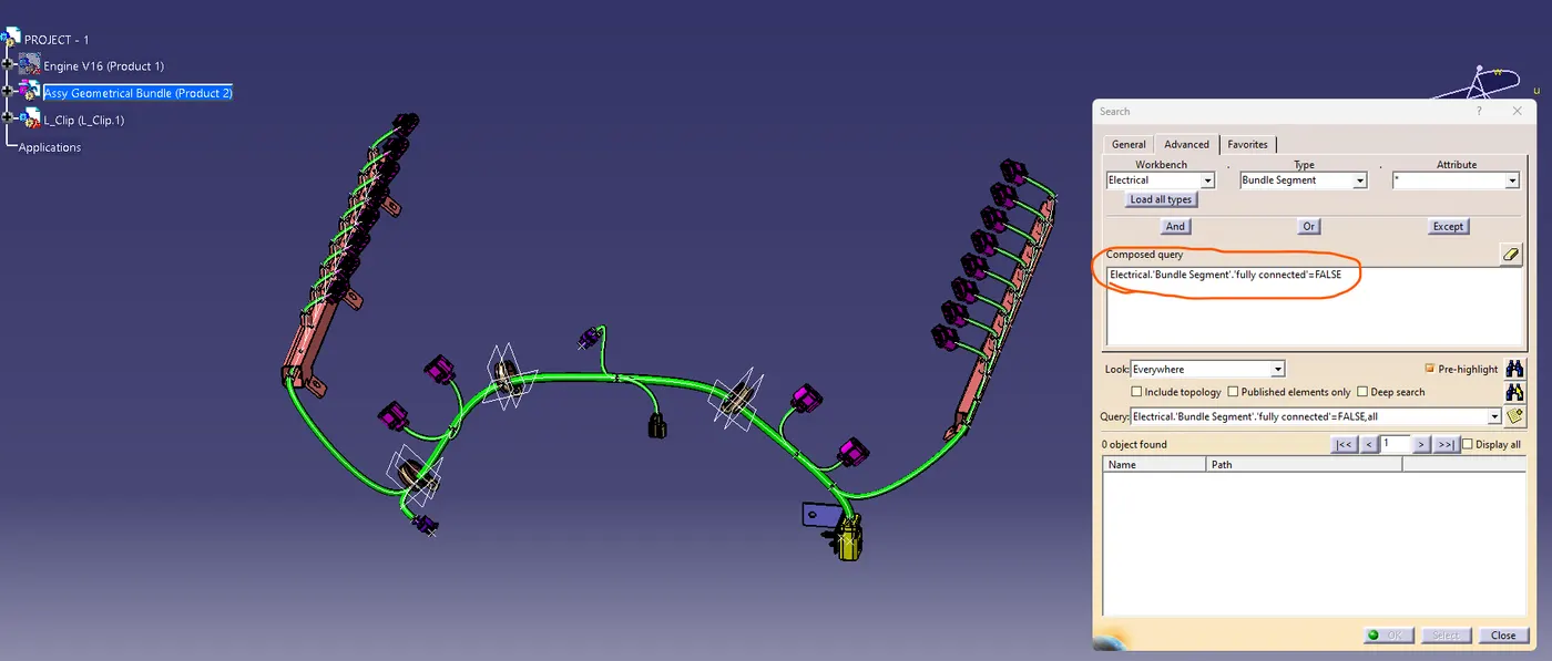
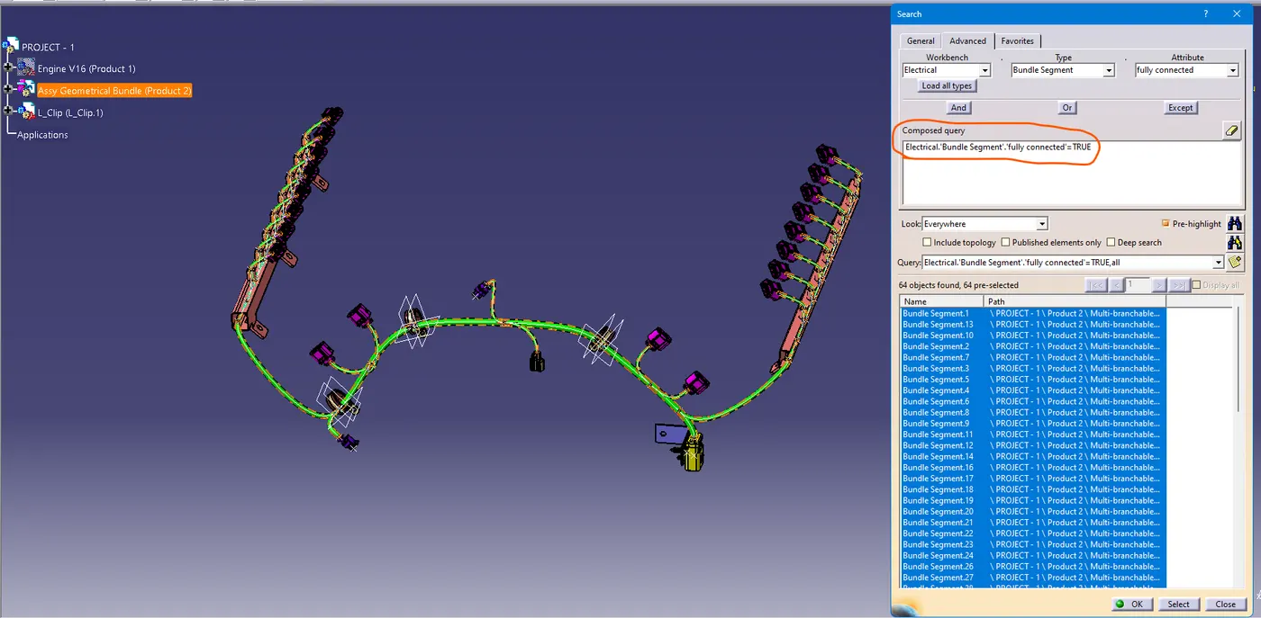
- After routing the product, check whether the bundles are fully connected.
- Add protective coverings on the wiring harness to protect wiring from high temperature. They are created by using define protection part command in the electrical part design workbench. Select part , and define the parameters as per the requirement.
- The created corrugated tube can be added into the catalog by store device command and selecting the catalog file created for protective covering. then appropriate protective covering added to the bundle segments.
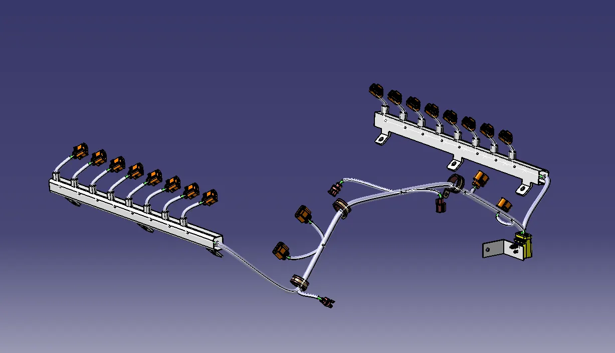
WIRING HARNESS FLATTENING
- Create a new product file for flatten the wiring harness and save it in the same folder where the wiring Harness is saved.
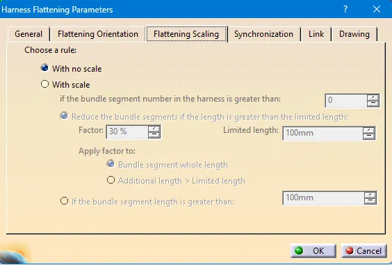
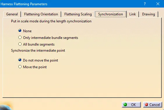
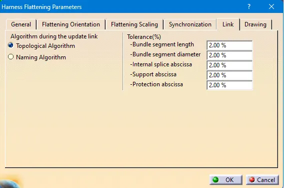
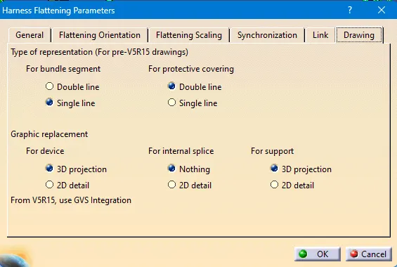
- Then switch to Electrical harness flattening workbench and select harness flattening parameters and define harness flattening parameters and the file notation will be changed to _Ehf.
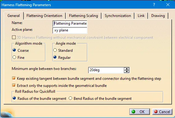 |
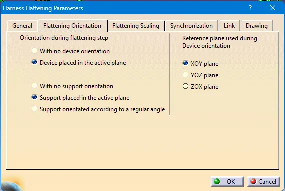 |
 |
 |
 |
 |
- Select all the Branches and Flatten the entire Geometric Bundle.
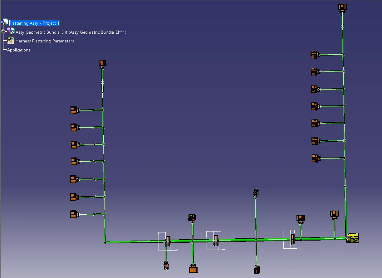
- Bundles can be Rotated and Rolled with a Proper Radius in Order to Fit the Drawing Sheet.
- Create a new drawing file in the drafting Workbench
- Insert the flattened harness product into the drawing sheet using front view option
- Modify the Drawing Sheet with Required Parameters.
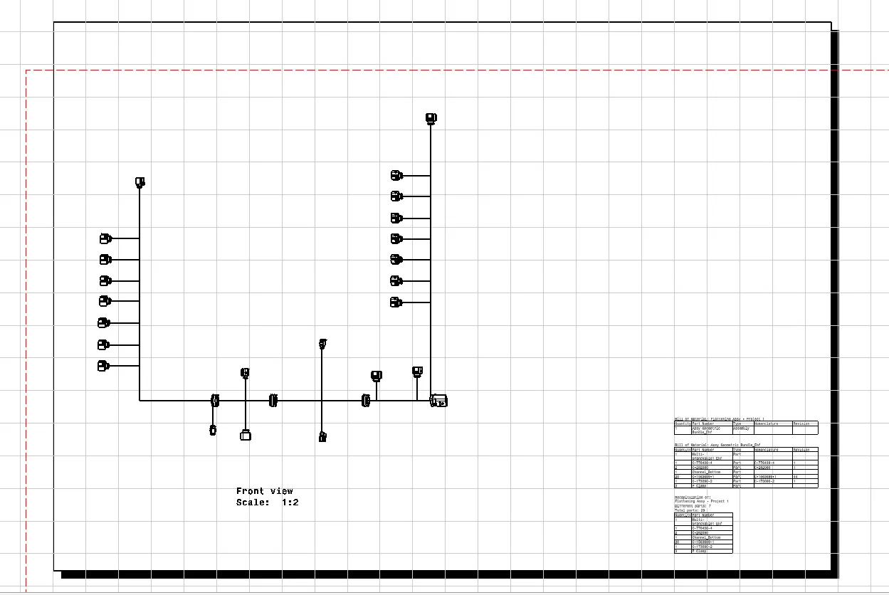
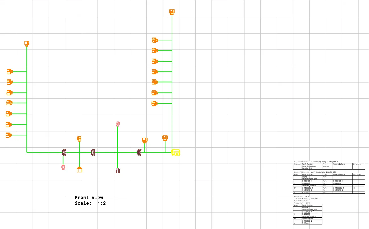
FINAL PRODUCT
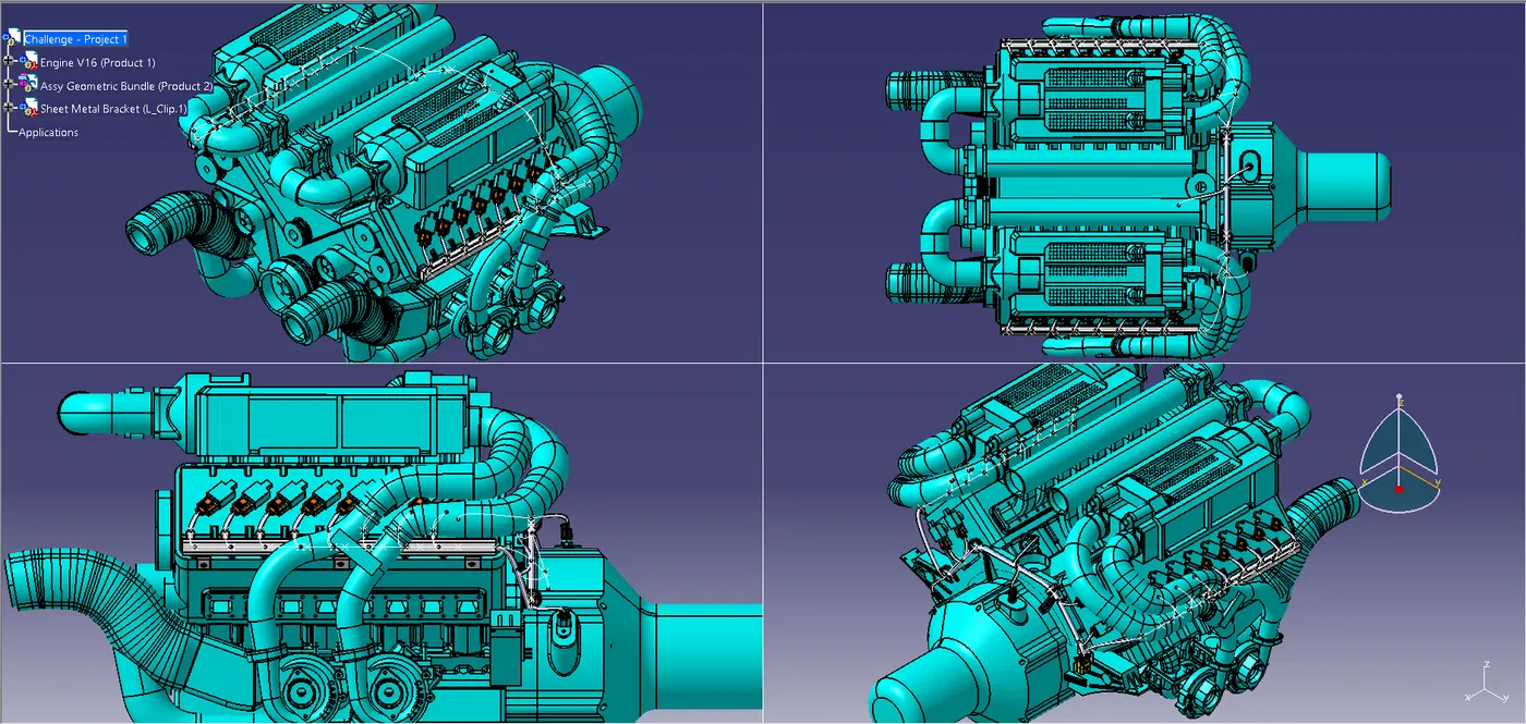
NOTE
- All the inputs used, images, and product file attatched below in separate folders.
- CATPart, Catalogue, CATProduct all are attatched
File Link: - https://drive.google.com/file/d/1BF8a7Q8opaZdkg-JAGr2A82xcfl1w7dK/view?usp=drive_link