Week 10 - Challenge 1- Attachment Feature Creation (Ribs & Screw Boss)
WEEK 10 - CHALLENGE 1
AIM - Create the Screw boss for the Drill Handle considering the design rules.
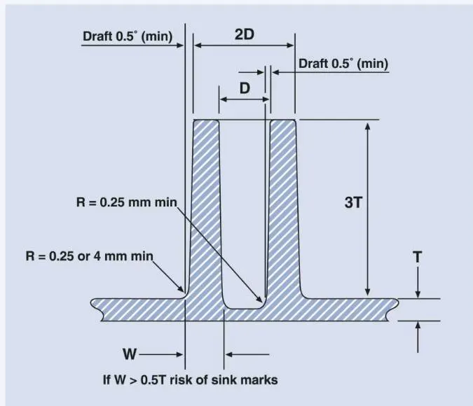
General Guidelines for Bosses:
- Draft - 0.5 degrees on the walls of boss
- Thickness - Typically 40%* of the nominal wall at the base.
- Height to Diameter Ratio - 3:1
- Radii - 0.25mm maximum radii.
REPORT
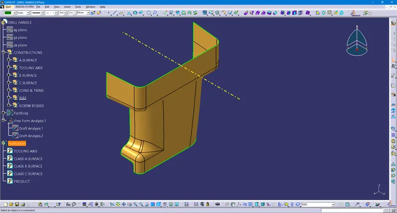
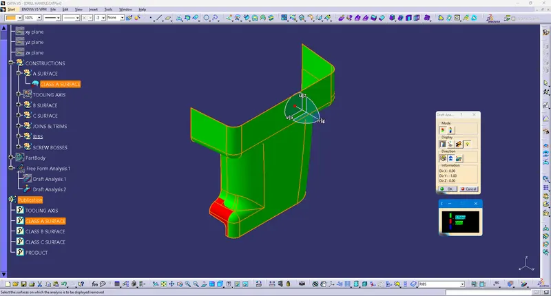
- Class A surface is given as CATpart and .stp file along with the question.Draft analysis of Class A surface has been done.
- Created a dummy tooling axis with point and line creation commands. With the help of Intersection and plane command the exact tooling axis is created in respect to bisecting method.
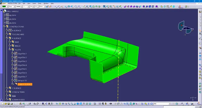
- Class B surface has progressed with Extract, Boundary, Extrapolation, and Surface Untrim commands. Final trim and offset are used to create the partbody of 3mm thickness.
- Sufficient fillets are provided with subtracting 2.5 - 3 mm from the Class A surface for proper alignment during final trim.
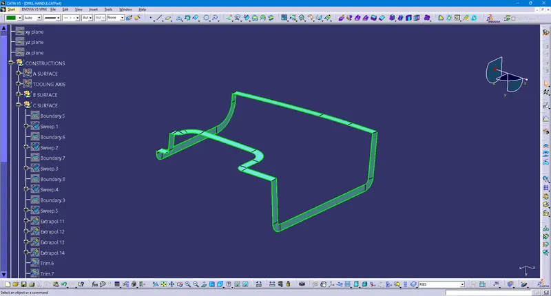
- Class C surface creation with Boundary, Sweep and trim commands followed with Class A and C join as to trim it with Class B surface for the final product generation.
- After the creation of Class A, B, C surfaces, had started the designing of ribs and screw boss as per given in question.
- Ribs are designed with,
- Draft - 0.5 deg
- Thickness - 40% of Wall thickness = 0.4 x 3 = 1.2 mm
- Height < 5*wall thickness = 5 x 3 = 15mm
- Minimum thickness at Top = 0.75 mm
- Fillet = 0.25 mm
- Rib root thickness is measured with tritangent circle creation and is of 3.2 mm with 3 mm of wall thickness. Along with that, Minimum height at top is of 0.968 mm.
- And for Screw boss,
- W > 0.5T; W need to be greater than 1.5 mm and given of 1.65mm.
- Height = 3T = 9mm
- Draft - 0.5 deg
- Fillet = 0.25 mm
- Spacing of 3: 1 ratio
- All the designing procedure are properly followed and published all according to time of completion.
IMAGES / SCREENSHOTS
- CLASS A SURFACE
- CLASS B SURFACE
- CLASS C SURFACE
- FINAL PRODUCT
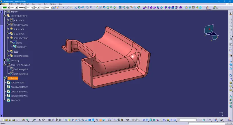
- COMPONENT WITH RIBS AND SCREW BOSSES AS PARTBODY
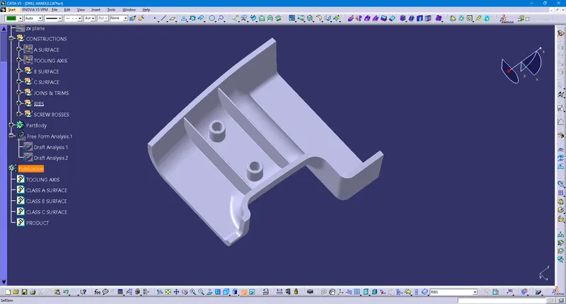
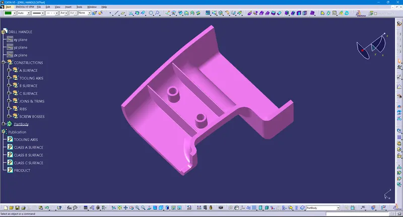
- FINAL COMPLETE PARTBODY
- DRAFT ANALYSIS
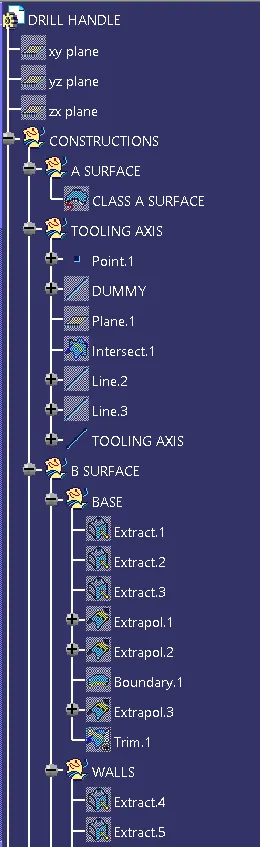
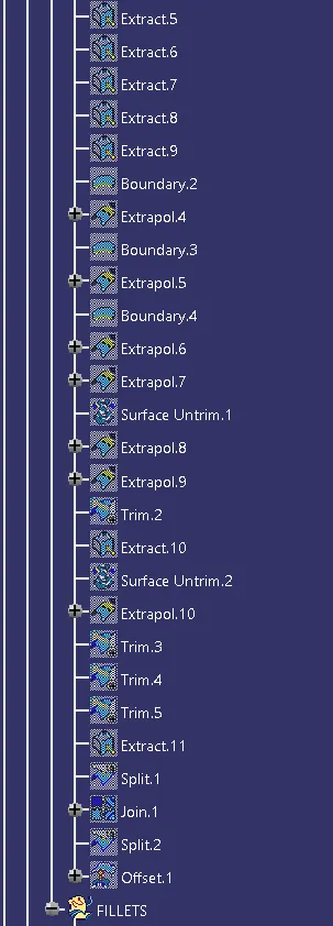
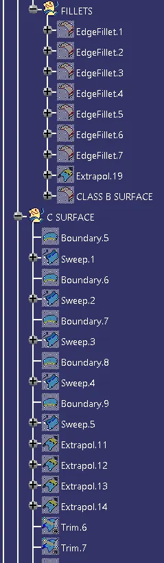
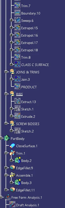
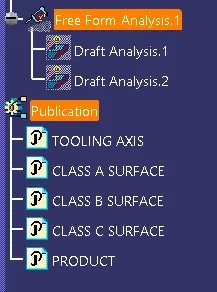
- TREE STRUCTURE
NOTE:
- Positioned sketches are used and are Iso-Constrained
- Proper Tree Structure is maintained
- Geometrical sets are properly named based on the sketches present inside.
- All the sketches are created under the Geometrical set.