Week 9 - Challenge 2 - Switch Bezel Design
WEEK 9 - CHALLENGE 2 - SWITCH BEZEL DESIGN
AIM - Create the Switch Bezel Plastic component through the given Class-A surface. To begin with, the tooling axis for the given Class-A Surface should be created meeting the requirements of the draft angle and at the end perform the Draft analysis on the model. Thickness of the component - 2.5 mm.
REPORT
- Class A surface is been attatched with the question provided with the challenge.
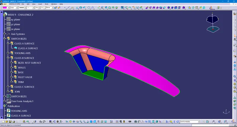
- Initially separate the surfaces with applying different colours and identifying drafting side or axis.
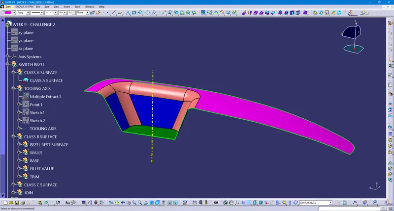
- Create the Tooling axis with bisecting method which mentioned in question itself. For that, project the 3D element from the surface and dentified as the pocket be the most suitable area to allign the tooling axis.
- Create a Axis system with a point which is defined followed by two parallel dummy lines in the surface with reference to XZ and YZ plane and bisect in creating two lines and contnuing same bisect to the reference output in creation of tooling axis aligned with newly created Axis system.
- Class A Surface need to be simplified without fillets for proper generation of Class B surfaces.
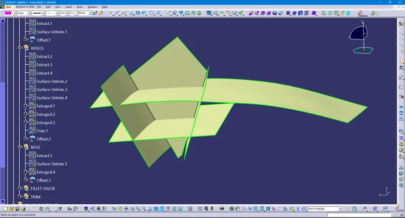
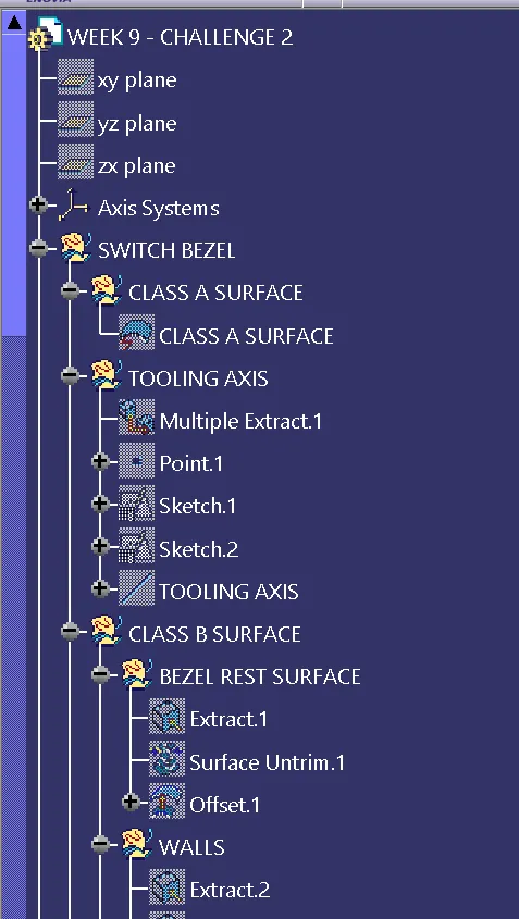
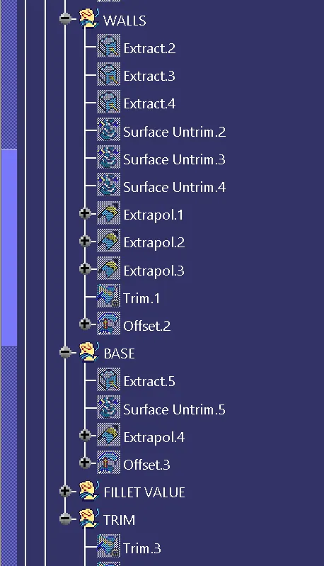
- Extract, Untrim, Offset operations are performed for each surface separately in Bezel rest surface, Walls, Base parts as defined in tree structure.
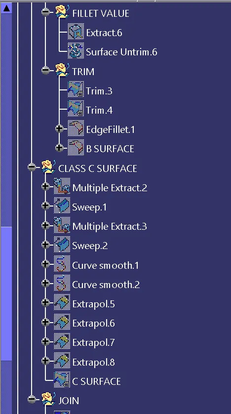
- Process it with sufficient trims and edge fillets to form output for B surface and Class B surface is ready.
- Initiation of Class C surface with Multiple extract / Boundary command followed by sweep and extrapolate operation, enhances generation of C surface. Smoothen the curve to remove the patches which will make difficult and rough profile while manufacturing.
- Join Class A surface with C surface and trim the resulting output with Class B surface in creation of final output.
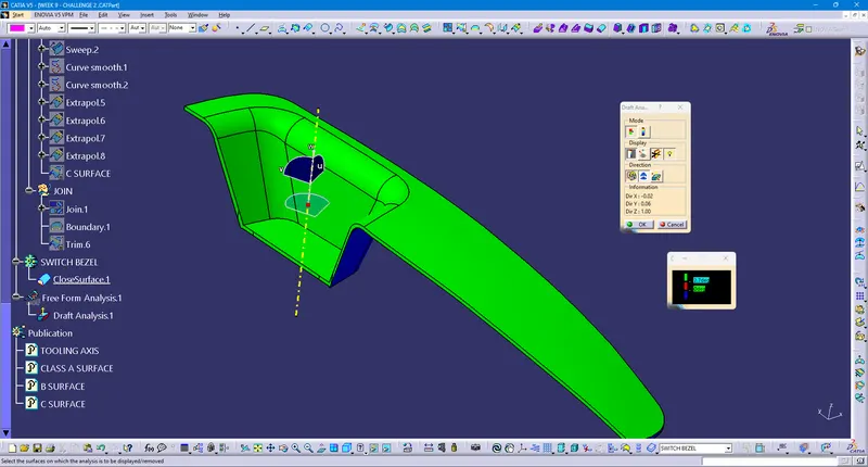
- Draft analysis is performed and report is being attatched with screenshots below.
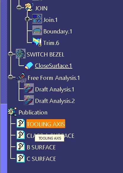
- Tooling axis, Class A, B, C surfaces are published in accordance with its time to time creation.
IMAGES / SCREENSHOTS
- CLASS - A SURFACE WITH COLOR DIFFERENTIATION FOR SEPARATE SURFACES
- TOOLING AXIS IN CLASS - A SURFACE
- CLASS - B SURFACE
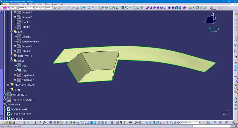
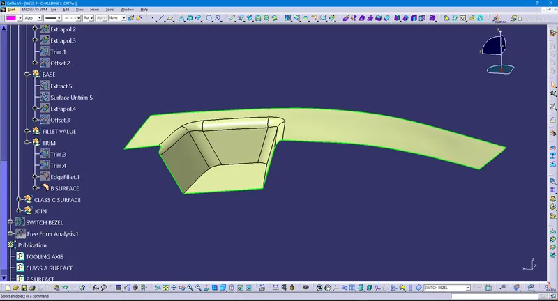
- C SURFACE
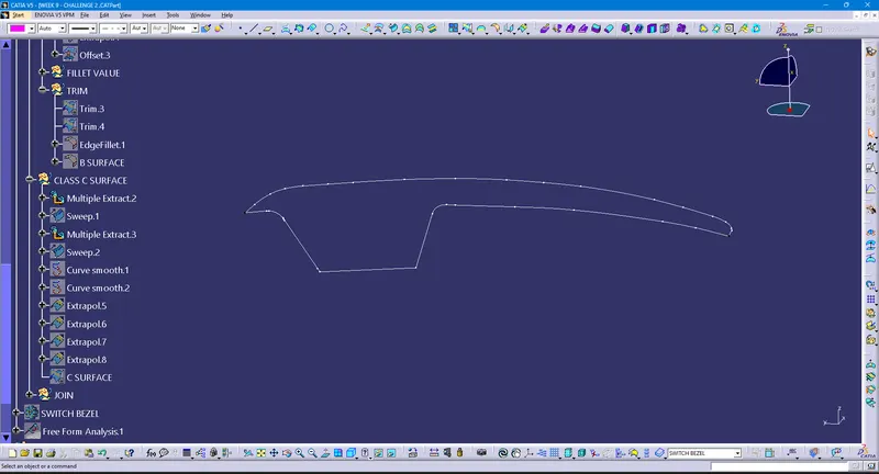
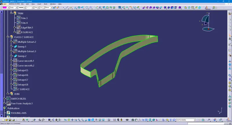
- OUTPUT
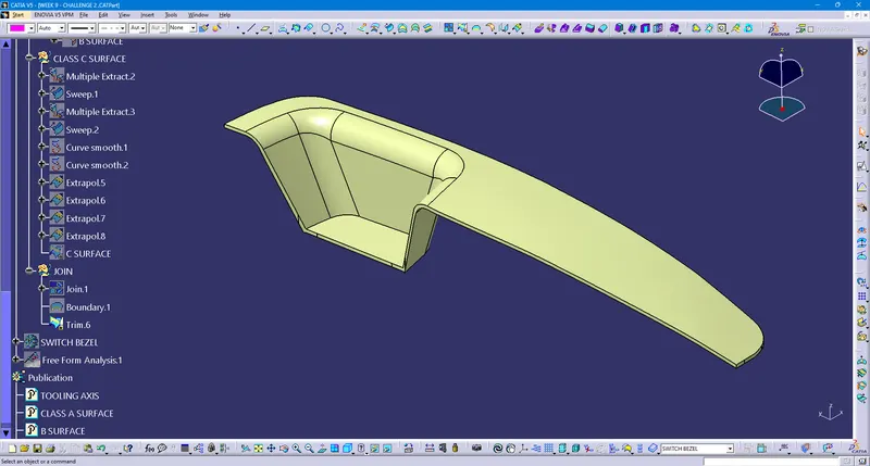
- PARTBODY DEFINED WITH CLOSE SURFACE
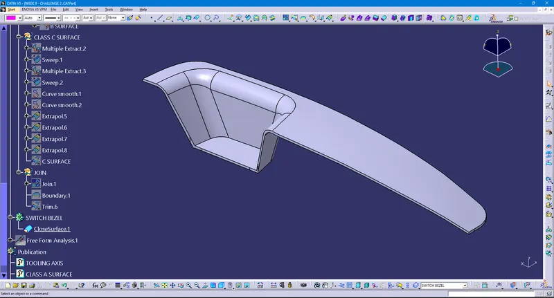
- DRAFT ANALYSIS OF FINAL COMPONENT
- 3D PARTS
ISOMETRIC VIEW
FRONT VIEW
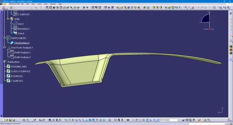
SIDE VIEW
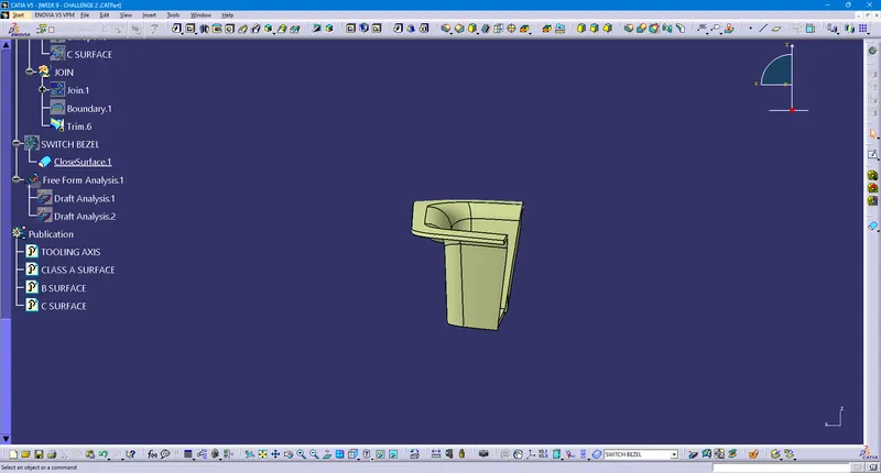
TOP VIEW
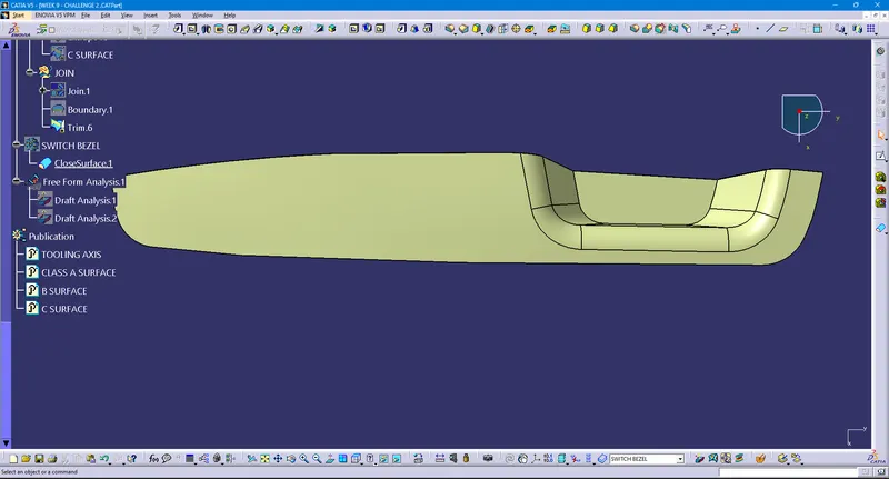
- TREE STRUCTURE
NOTE:-
- Proper Tree Structure is maintained.
- Geometrical sets are properly named based on the sketches present inside.
- All the sketches should be created under the Geometrical set.
- Close Surface feature is used to make a solid body from the surface.
- Tooling Axis, Class A, B, and C surface are published.