Week 9 - Challenge 3 - Bumper
WEEK 9 - CHALLENGE 3 - BUMPER DESIGN
AIM - Create the Bumper Plastic component through the given Class-A surface. To begin with, the tooling axis for the given Class-A Surface should be created meeting the requirements of the draft angle and at the end perform the Draft analysis on the model. Thickness of component = 3 mm.
REPORT
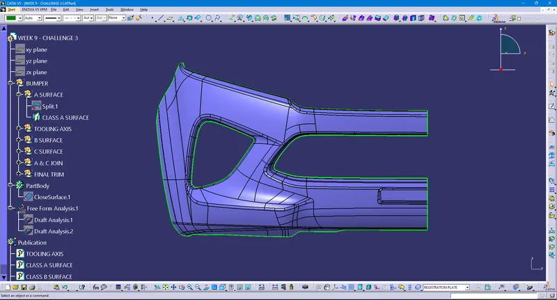
- The given Class A Surface is in inverted position, for convienience it had symmetried in YZ plane and named as Class A Surface, subjected to publication.
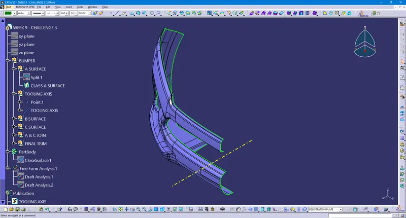
- Creation of tooling axis is done with respect to the point and line created on curve of the component.
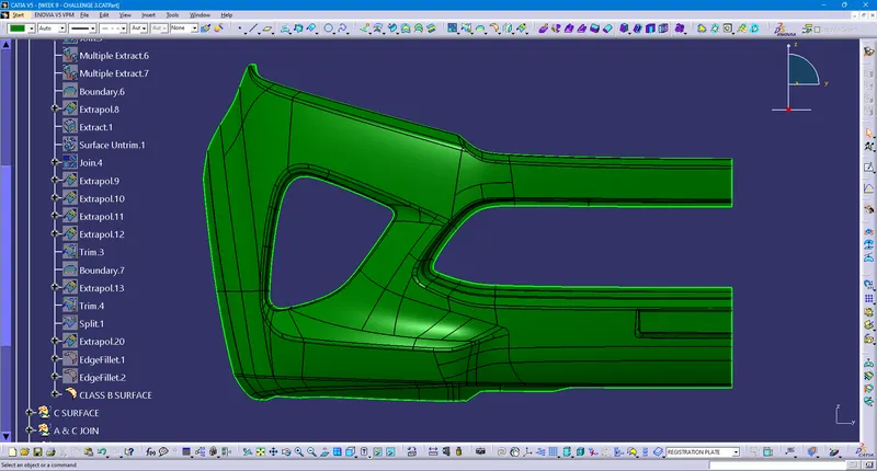
- Initiation of B Surface creation, following Direct offset method due to surface complexity. The B surface is splitted to 3 parts for convienience in tree structure as Top, Centre Grill, Registration plate.
- Each solved individually with an idea to eliminate fillets by following Offset, Multiple Extract, Boundary, Extrapolation and Trim commands.
- As Final step, split, join, and edge fillets are used to create the Class B Surface.
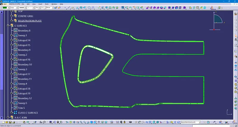
- After B Surface, next step to create C surface with Boundary, Sweep, extrapolate commands wrt A surface. A final trim with the external disturbances led to Class C surface.
- As part of final stage, we need to join Class A and Class C surface followed with trim between Class B surface and the output of Class A and Class C join.
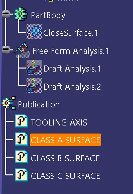
- Final product is generated and is subjected to check presence of any open boudary with Boundary or Join commands. After its successive completion final product need to defined in partbody with Close Surface feature.
- As of the last and final stage, partbody is subjectd to draft analysis and is cleared with 3 degree draft.
- Tooling Axis, Class A, B, C surfaces are published accordingly with its time of creation.
IMAGES/SCREENSHOTS: -
- CLASS A SURFACE
- TOOLING AXIS
- CLASS B SURFACE
- CLASS C SURFACE
- CLASS A & C JOIN
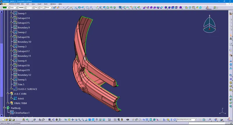
- FINAL PRODUCT
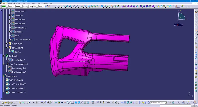
- DRAFT ANALYSIS
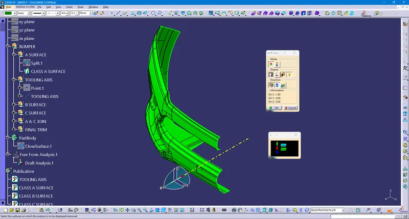
- PART BODY
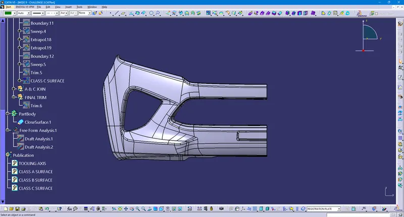
- ISOMETRIC VIEW
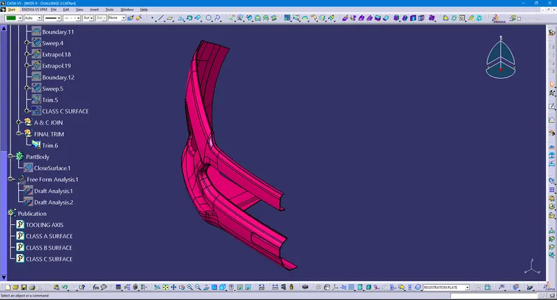
- FRONT VIEW
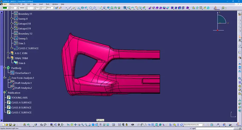
- BACK VIEW
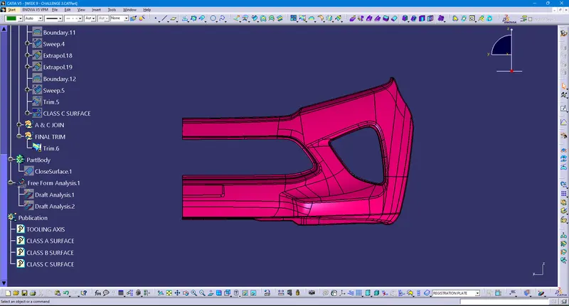
- SIDE VIEW
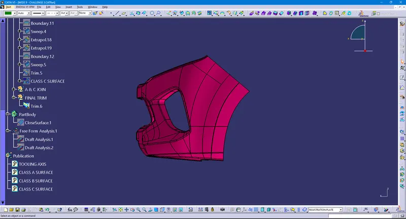
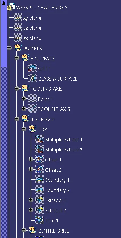
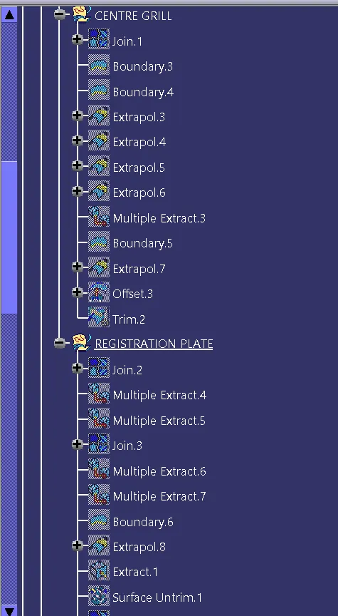
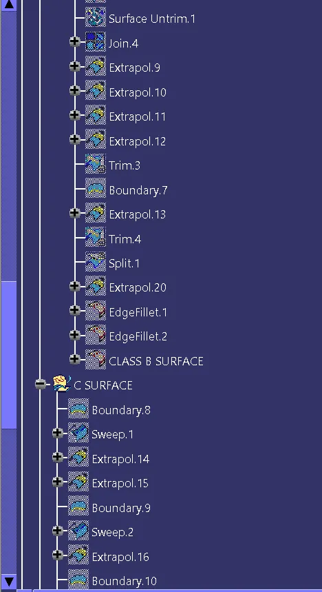
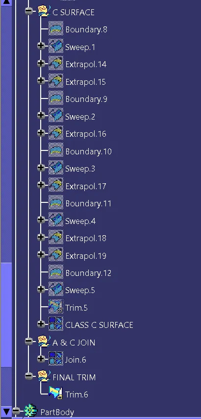
- TREE STRUCTURE
NOTE:
- Proper Tree Structure is maintained
- Geometrical sets are named based on the sketches present inside
- All the sketches are created under the Geometrical set
- Close Surface feature is used to make a solid body from the surface.
- Tooling Axis, Class A, B, and C surface are published accordingly.