Week 9 - Challenge 1 - Base Bracket Design
WEEK 9 CHALLENGE 1 - BASE BRACKET DESIGN
AIM - Create the Base Bracket Plastic component through the given Class-A surface. To begin with, the tooling axis for the given Class-A Surface should be created meeting the requirements of the draft angle and at the end perform the Draft analysis on the model. (Thickness of Plastic Part - 2.5 mm).
REPORT
- As the CATpart is provided with the question, which used as the basic reference in performing thee draft analysis.
- Class-A surface is the aesthetic part in a mechanical partbody, is defined in workbench.
- Tooling axis is created with Class-A surface and a Dummy tooling axis. And the dummy is created by bisecting the lines protruded from the both sides of complex structure in given part through intersecting method.
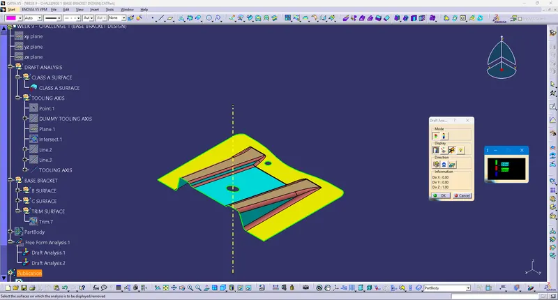
- Draft analysis for Class - A surface had been done, its output been good to proceed for the next procedures.
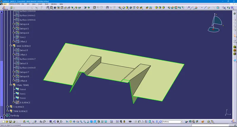
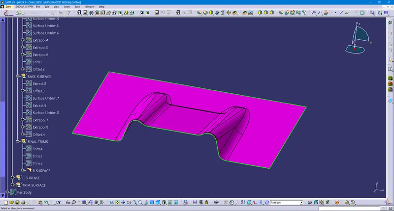
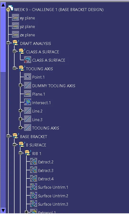
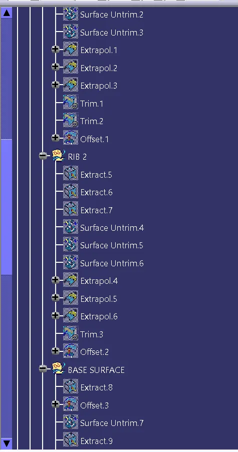
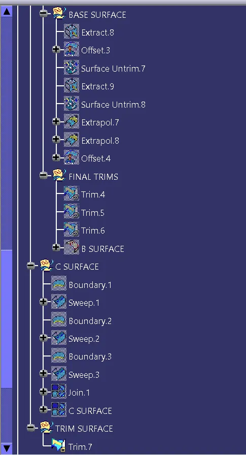
- Creation of B surface had initiated and splitted to 3 different parts as RIB 1, RIB 2, and Base Surface which is evidently mentioned in tree structure.
- Extract, Surface Untrim, Extrapolation, Trim and Offset operations are done in order for RIB 1, 2 and Base Surface individually.
- After applying edge fillets of (3mm + 2.5mm) and final trims B Surface has been created.
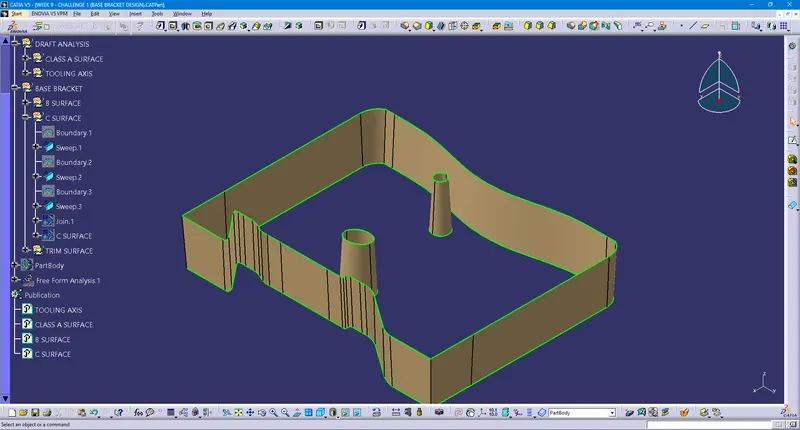
- After the completion of B Surface, C Surface process had initiated by selecting Boundary to be defined, followed by sweep command in draft mode of 3 degrees and join operation for main body and holes.
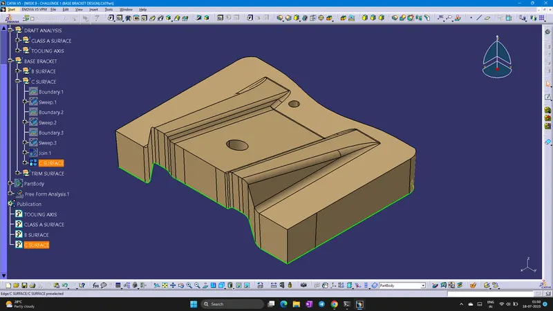
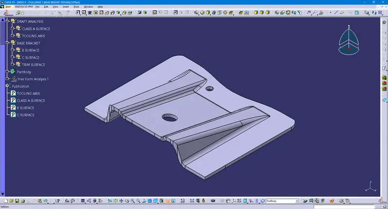
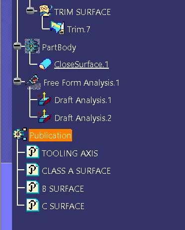
- Final stage of Trim between A and C surface, the final product is generated. It is defined in part workbench and has entitled with Close Surface feature is used to make a solid body from the surface.
IMAGES / SCREENSHOTS
- TOOLING AXIS
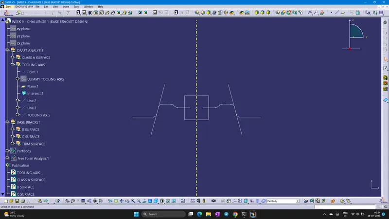
- CLASS - A SURFACE
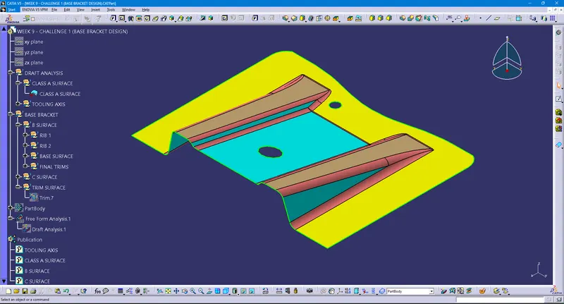
- B SURFACE
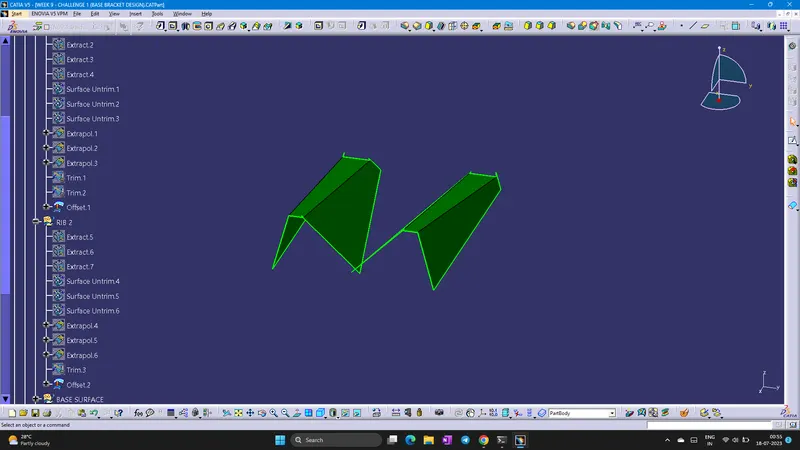
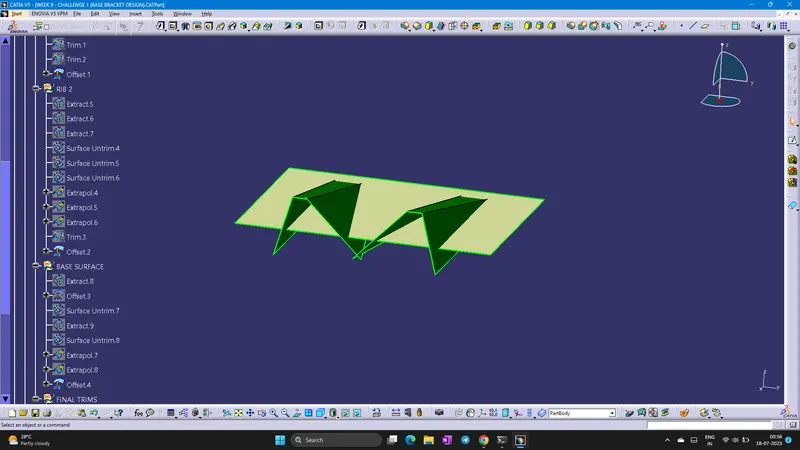
- C SURFACE
- FINAL PLASTIC COMPONENT
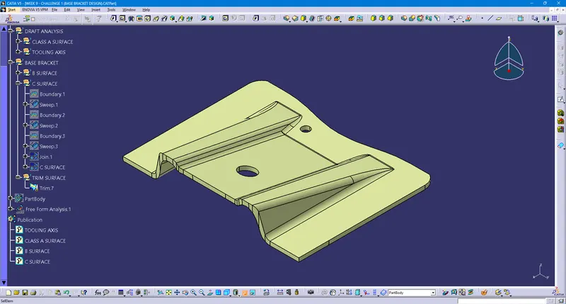
- FINAL PLASTIC COMPONENT- PARTBODY DEFINED
- DRAFT ANALYSIS REPORT FOR CLASS - A SURFACE
- DRAFT ANALYSIS REPORT FOR FINAL PLASTIC COMPONENT
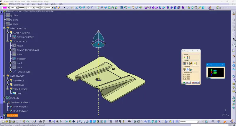
- ISOMETRIC VIEW
- FRONT VIEW
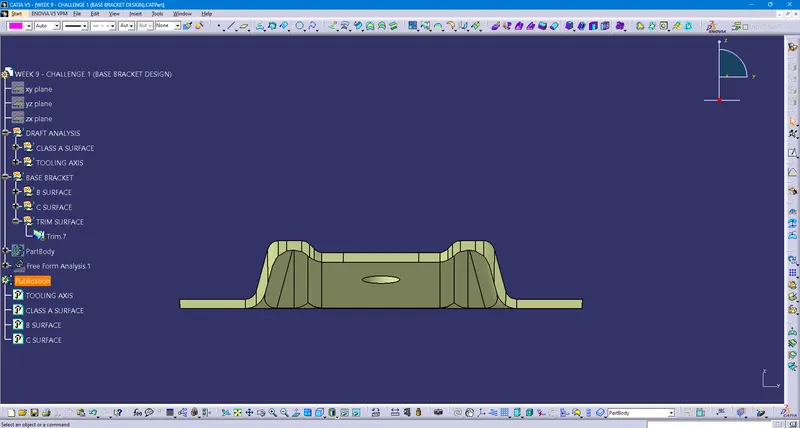
- TOP VIEW
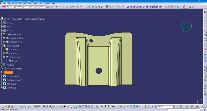
- DETAILED TREE STRUCTURE
NOTE:-
- Proper Tree Structure is followed.
- Geometrical sets are named properly, based on the sketches present inside.
- All the sketches are created under the Geometrical set.
- Close Surface feature is used to make a solid body from the surface.
- Tooling Axis, Class A, B, and C surface are published.