Project 1
Route the Wiring harness on Given Engine and Prepare flatten view drawing in CATIA V5. Application of all Packaging rules, Industry best practices studied in this course shall be demonstrated in design..
ENGINE WIRING HARNESS ROUTING
Given V16 engine
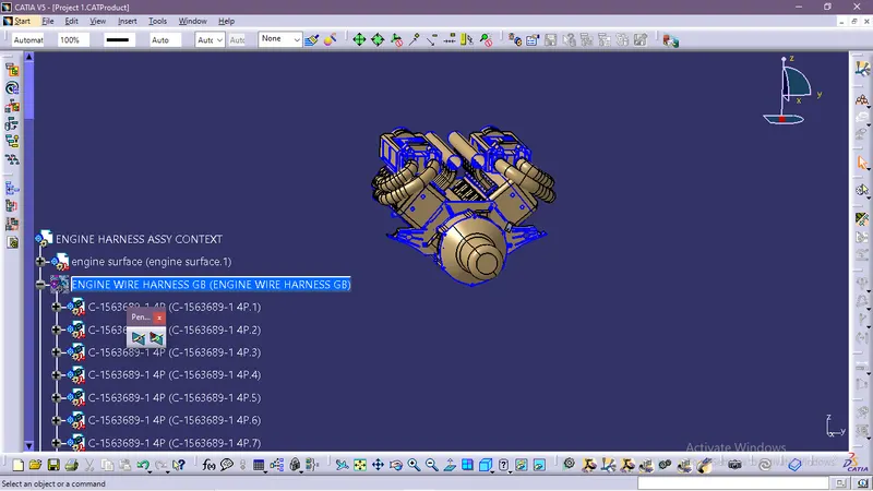
The above figure shows the given V16 engine cad data .Here routing the wiring harness for the following electrical components attached to the engine.
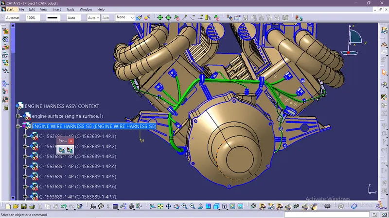
- fuel injector for each cylinder we have 16 cylinder engine
- camshaft sensors on each engine block (4 camshaft sensor )
- Engine coolant sensor at the centre of the engine between the two blocks
- Engine oil temperature and oil pressure sensor fitted at the oil sump of the engine on both engine cylinder blocks
- sensors for sense neutral positon of the transmission assembly and measure the vehicle speed
- Interconnection connector to connect engine harness system to vehicle harness system.
Harness mounting and routing management required to provide proper packaging of the wiring harness.it also deals with clearance management and manufacturability
- P-clamps to provide positive clamping and proper clearance management for the routing
- Mounting clips for connector mounting
- Guiding channels provide thermal protection in high temperature zones .
- Corrugated tubes used to protect the wiring harness from hazardous liquids and temperature
Next create a new product in assembly workbench named as assembly wiring harness contex .it is the top level product file inside this product file created geometrical bundle and wire harness electrical bundle.Given V16 engine cad data added inside this contex assembly.
Geometrical bundle contains all of the harness components i.e connectors ,clip, gromets and actual physical bundle segments and branches.All the components should be defined electrically .
Download the 3d data of required connectors and mountings from the site www.te.com
- define the connectors electrically by defining all its properties shown in the below fig.
open the cad data of connectors in catia part design workbench and create the connector connection point,connector connection axis system , bundle connection point .Then Switch to electrical part design workbench and define it as a connector also define connector connection point and bundle connection point.
Here we have inter connection connector it require mounting clip for mounting the connector .so cavity connection point should be defined for this connector.
All the connectors defined as electrical connector and defined all the necessary properties to Connectors.Created a catalog document in connector family and stored all the connector data in catalog document .
download the other harness mountings like clips and clamps cad data.Also download the brackets for parking the interconnection connectorand channel for routing the harness in high temperature zones
final wiring harness
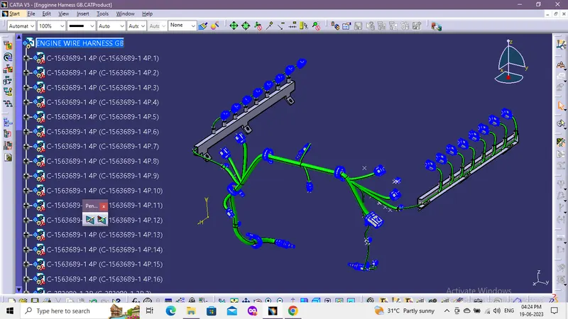
Note : Due to less software problem the software is shutting down again and again.