Project 1
WIRING HARNESS FOR ENGINE
PROJECT-1
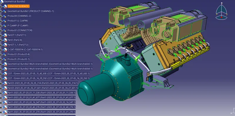
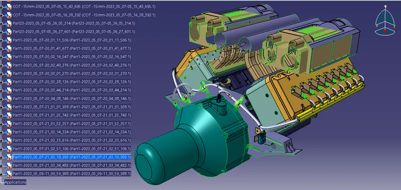
Aim- To route the wiring harness of Engine model, protection covering and prepare flatten view drawing in CATIA V5.
Objective- Objective of this project is to route the wiring, protection covering and prepare flatten-view drawing for the given V16 engine model and considering all types of packaging rules constraints while routing the wiring harness .All necessary detsils like clearance/clamping selection,harness fixing requirements,harness continuity should be provided in order to design the wiring harness.
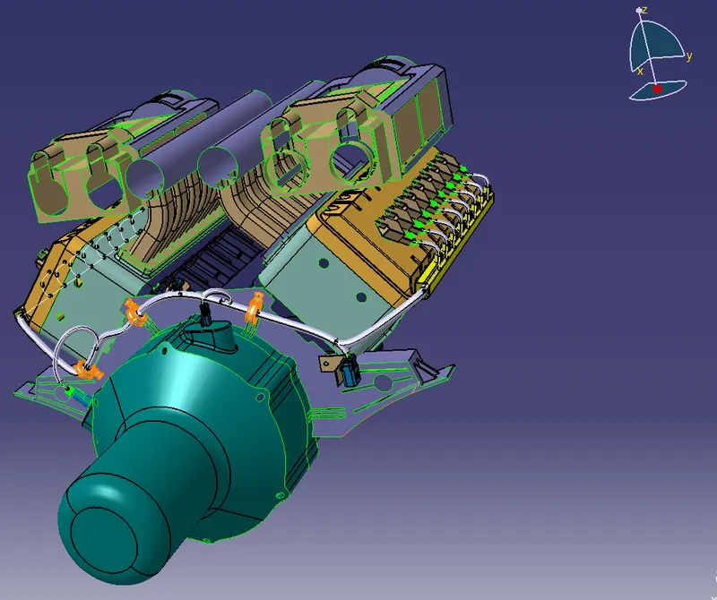
iring hamess routing shall provide ease in manufacturing, accessibility, easy removal, and easy maintenance of attached equipment and wiring harness.
• Routing through small structural holes and openings shall be avoided, minimize chaffing and handling of the wiring harness during installation
- Avoid the harness routing and clipping in the Blind zone of the Operator during harness assembly or in service.
- Routing shall offer protection against possible damage through common misuses such as being handhold and temporary support for test equipment.
- Provide additional slack to the harness according to the surroundings and harness bending requirements. Ensure the routing meets the clearance requirements with different surrounding parts.
- Avoid routing over the bolts, near to the bolted joints. It may damage the harness or puncture the harness. Keep harness away from panel mounting screws.
- Avoid harness routing near sharp edges, if not possible provide protection to the harness. The maximum distance between two clips on a straight branch is 200mm.
- Provide Clips and clamps if the hamess is going to bend at multiple locations. The use of too many sheet-metal brackets should be avoided.
- The branch length should be more than 50 mm.
- Min distance between clip and branching point to be 25 mm, Min distance between two branch breakouts should be 50 mm.
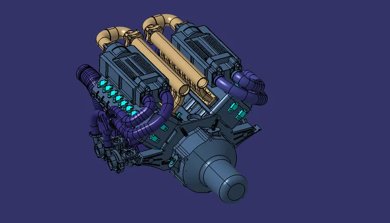
The given engine model has 16 fuel injector sensors and 4 cam-shaft sensors that is a total opf 20 sensors.We used 4 pole connectors for fuel injector sensors and for cam-shaft sensors also.
The engine will also have an interconnection connector which will connect the engine to other parts of the vehicle.We used 12-pole electrical connector with a mounting clip feature as an interconnection connector.
The plastic guiding channel used in this harness should be made of a material that can withstand atleast 150 deg celcius.
COMPONENTS:
(a).Connectors:
1.
Part No : C-173090-2
No of terminals: 2
No of Quantity : 2
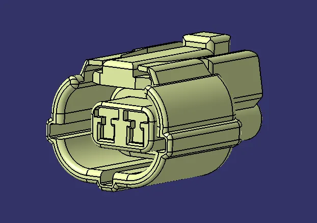
2.
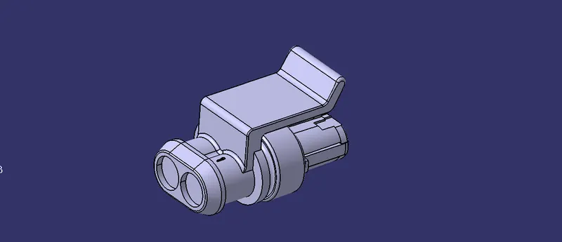
Part No : C-282080-1
No of terminals: 2
No of Quantity : 3
3.
Part No : C-1563689-1
No of terminals: 4
No of Quantity : 20

4.
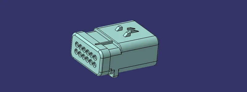
Part No : C-776438-4
No of terminals: 12
No of Quantity : 1
(b).Mounting Equipment:
1.
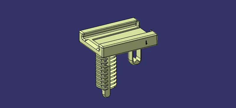
Part No : C-1924487-2
No of Quantity : 1
2. Firr Tree Clip:

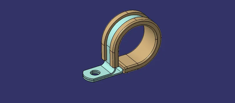
3. P Clamp:
GIVEN ENGINE:
PACKAGING RULES:
- Wiring harness routing shall provide ease in manufacturing, accessibility, easy removal, and easy maintenance of attached equipment and wiring harness.
- Routing through small structural holes and openings shall be avoided, minimize chaffing and handling of the wiring harness during installation.
- Avoid the harness routing and clipping in the Blind zone of the Operator during harness assembly or in service.
- Routing shall offer protection against possible damage through common misuses such as being handhold and temporary support for test equipment.
- Provide additional slack to the harness according to the surroundings and harness bending requirements.
- Ensure the routing meets the clearance requirements with different surrounding parts.
- Avoid routing over the bolts, near to the bolted joints. It may damage the harness or puncture the harness. Keep harness away from panel mounting screws.
- Avoid harness routing near sharp edges, if not possible provide protection to the harness.
- The maximum distance between two clips on a straight branch is 200mm.
- Provide Clips and clamps if the harness is going to bend at multiple locations.
- The use of too many sheet-metal brackets should be avoided.
- The branch length should be more than 50 mm.
- Min distance between clip and branching point to be 25 mm.
- Min distance between two branch breakouts should be 50 mm.
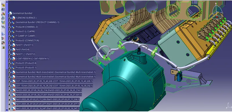
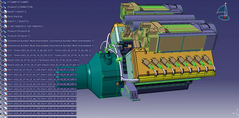
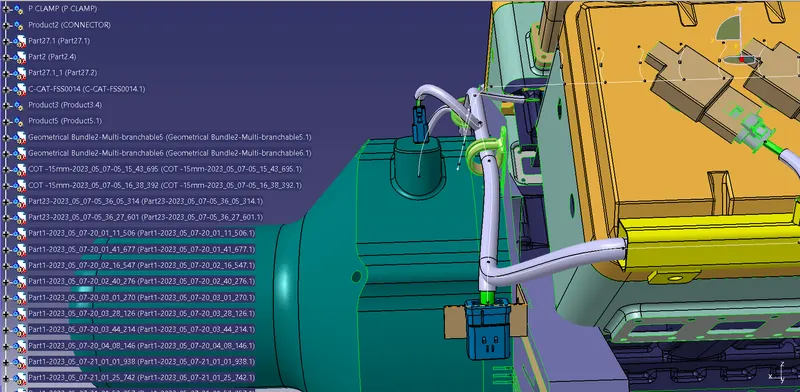
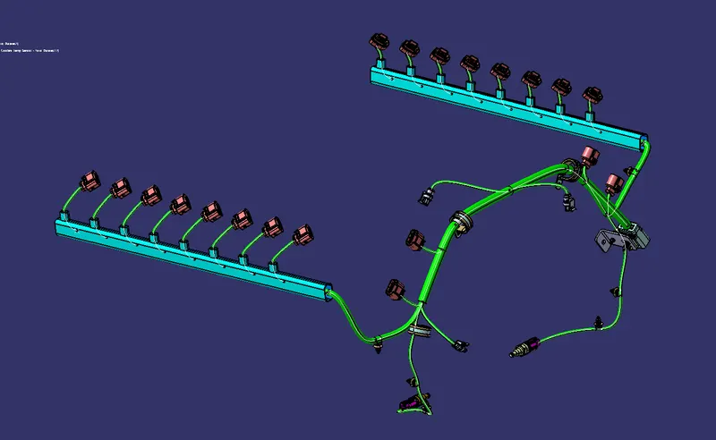
HARNESS ROUTING:
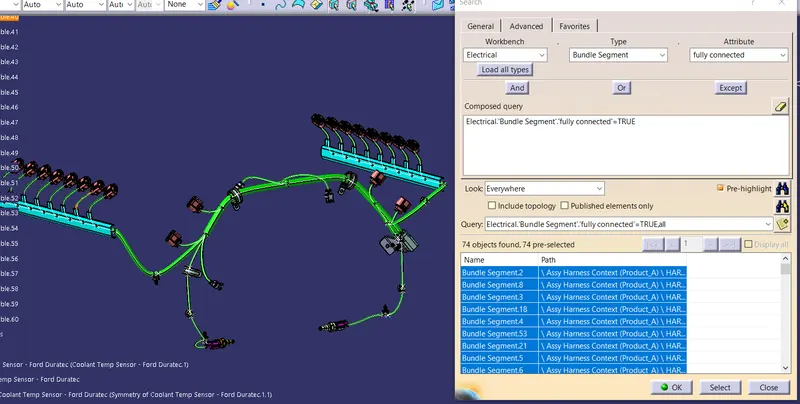
CONNECTIVITY CHECKUP:
TREE STRUCTURE: