Project 1
1. Design a battery pack for a car roughly 150 Kw with 120 V. Use 3500 mAh 3.6V nominal NMC chemistry cell.
a. Design the battery pack configuration.
b. Draw the BMS topology for this battery pack.
Answer:
Objective:
To design a battery pack for a car roughly 150 Kw with 120 V, to design the battery pack configuration and to draw the BMS topology for this battery pack.
Calculation:
A Battery management system(BMS) is said to be the brain of a battery pack. The BMS is a set of electronics that monitors and manages all of the battery’s performance. Most importantly, it keeps the battery from operating outside of its safety margins.The battery management system is critical to the battery’s safe operation, overall performance, and longevity of battery pack.
There are 4 main BMS topologies;
- Centralised Topology
- Master and Slave topology
- Modular Topology
- Distributed Topology
To decide a topology for designing BMS, we have to consider 2 main parameters:
- Number of cells in series
- Application of BMS
To find the number of cells in series and number of cells in parallel;
Given data;
Nominal voltage for NMC battery = 3.6 V
Maximum capacity = 3500 mAh
Rated load voltage = 120 V
Load = 150 kW
Number of cells in series = Rated load voltage / Nominal voltage
=120/3.6 = 33.33
Rounding off to the highest number, since it is always advisable to round off to higher value so as to consider any kind of losses. So, Number of cells in series is 34 cells.
Number of cells in parallel = Required current /Nominal cell capacity
Required current = Power/Voltage = 150kW/120 = 1250 Ah.
Nominal cell capacity = 3500mAh = 3.5 Ah.
Number of cells in parallel = 1250 /3.5 = 357.14.
Rounding off to the highest number, since it is always advisable to round off to higher value so as to consider any kind of losses. So, Number of cells in parallel is 358 cells.
So, the battery pack configuration will be 34S358P.
Topology selection criteria:
If we have more than 18 cells in series for battery, then we can use Master and Slave Topology for designing BMS. If the number of cells is 18 or less than 18, then we can choose Centralised topology. For very large battery storage system, like more than 1 MW, we can use Modular topology. If number of cells is 18 or less than 18, we can also use Distributed Topology, however, it is not advisable to use, as there will be one AFE connected to each cell, which can make the system more complicated.
Since it is given that the system is 150 kW system, we dont have to use Modular topology. However, the number of cells in series is 34 which is more than 18 cells, it is advisable to use Master and Slave Topology.
BMS topology architecture:
For the Master and Slave Topology, there will be slaves communication with next slave and the final slave communicating with a Master and to the MCU.
Here, we have total of 60 number of cells in series.
Number of slaves = 34/18 = 1.8.
So, rounding off, we can use 2 slaves, 17 cells connected to each slave.
So, total number of cells would be 17*2 = 34, which is the desirable number of cells in series.
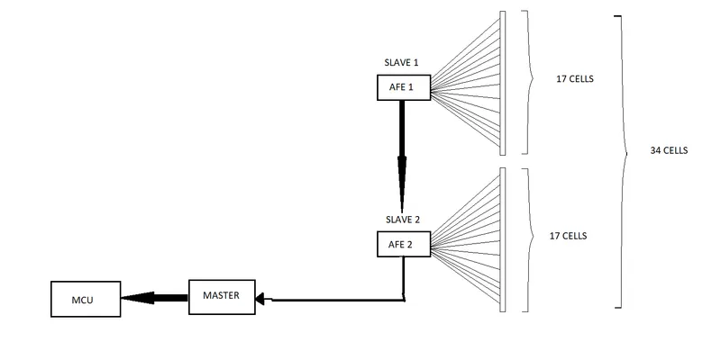
Here, we have connected 17 cells in series to AFE1 which serves as Slave 1, 17 cells in series to AFE2 which serves as Slave 2. AFE receive the data from 1st set of 15 cells and give to AFE2. AFE2 receives data from AFE1, and final set of 17 cells and gives the data to Master. The Master communicates with Microcontroller Unit (MCU) which processes all the data received from the total 34 cells, and provides data to actuator.
2. Build a 3S2P battery pack configuration with generic battery block using Matlab/Simulink.
Objective:
To build a 3S2P battery pack configuration with generic battery block using Matlab/Simulink.
Calculations:
We have to build a 3S2P battery pack configuration, which mean 3 cells in series and 2 cells in parallel.
Total number of cells in battery pack = Number of cells in series * Number of cells in parallel
So, Total number of cells = 3*2 = 6 cells.
Design, Parameters and Explanation:
Step 1: Arrangement of 6 cells:
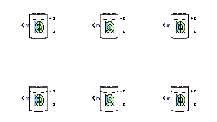
Here, we have placed 6 cells to be connected in series and parallel.
Step 2: Parallel connection:
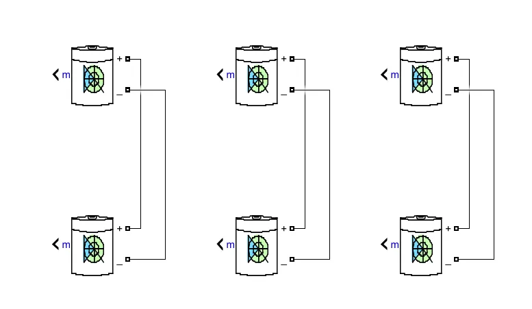
Here, batteries are connected in such a way that the positive (+) terminal of first battery is connected to positive terminal of next battery. And, negative (-) terminal of first battery is connected to negative terminal of next battery.
Step 3: Series connection:
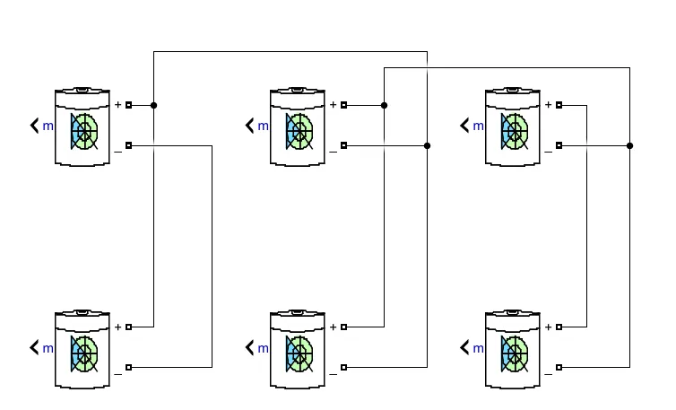
Here, batteries are connected in such a way that positive (+) terminal of first battery is connected to negative terminal of next battery. And the negative (-) terminal of first battery is connected to positive terminal of next battery.
Simulink Model:
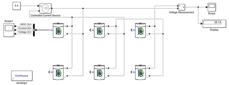
The above figure shows the 3S2P battery pack model. The voltage measurement block is connected across battery pack to measure battery pack voltage. The output of voltage measurement will be displayed in the Display block and Scope. Controlled current source is connected to voltage measurement block and battery as a load and a battery capacity of 5.4 is given as input to controlled current source. Bus selector is connected to battery to get the SOC%, Voltage (V) and current (A) which gives the output at the scope.
Battery parameters:
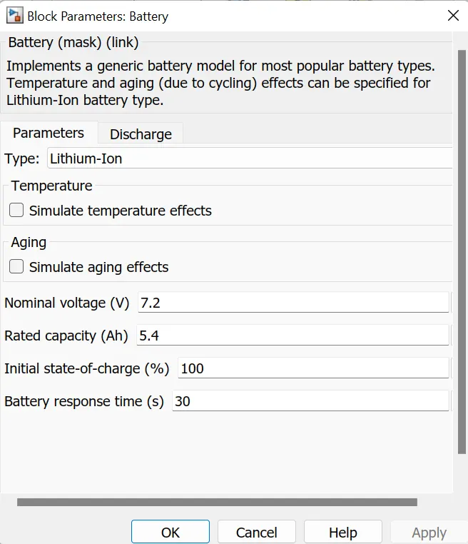
The Nominal voltage of cell = 7.2 V
Rated capacity of a cell = 5.4 Ah
Nominal voltage of battery pack = Number of cells in series * Nominal voltage of a cell
= 3 * 7.2 = 21.6 V
Rated capacity of battery pack = Number of cells in parallel * Rated capacity of a cell
= 2 * 5.4 = 10.8 Ah
This model is for an 21.6 V, 10.8 Ah battery.
Results:
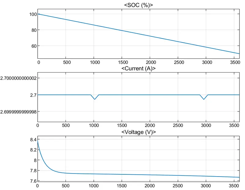
The above 3 plots show the SOC%, Current and Voltage output of single battery. The SOC% is reduced to 50% as the load is applied. Current signal will be determined by load and there is decrease in current due to regenerative braking. Voltage is around 8.3 V, and there will be increase and decrease in voltage, according to regenerative braking.
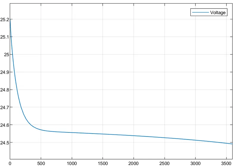
The above graph shows the overall voltage output of battery pack.
Overall voltage of battery pack = Number of cells in series * Maximum voltage of cell
= 3 * 8.3 = 24.9 V.