Project 1
Route the Wiring harness on Given Engine and Prepare flatten view drawing in CATIA V5. Application of all Packaging rules, Industry best practices studied in this course shall be demonstrated in design. Apply Protection coverings as required.
Prepare & Submit all necessary reports like clearance, Clipping/Clamping selection, Harness fixing requirements, Harness continuity, Assumptions if any along with CATIA 3D data
---------------------------------------------------------------------------------------------------------------------------
Project work is started with creating catalogue for required connectors.
Connectors .stp files are downloaded form the source website.
All parts are defined as electrical parts.
Protective devices are also created and saved in respective catalogues.
For the given egine harness assembly- connectors, p clamps are located and arranged on suitable positions.
Then Routing is started-
Routing is done for the given engine and input connectors with the engine.
For Interconnection connector, Connector 1 is used.
It is fixed on a L calmp. L clamp is located on engine bracket hole.
2 P clamps are fixed withe holes on bracket.
15 mm bundle diameter for main branch, 10 mm bunle diameter for the bundle in bottom channel and for other branches 5 mm bundle diameter is selected.
from main branch to other connectors, slack about 2 to 5 % is kept.
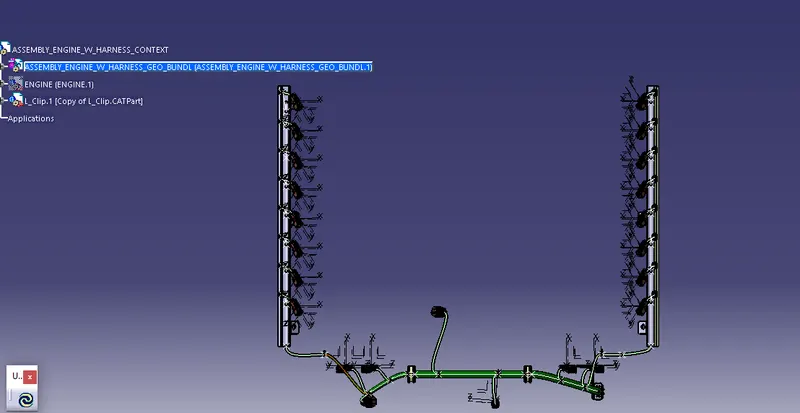
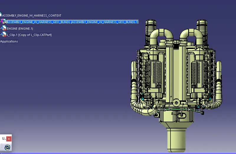
Flattening Assembly_engine harness-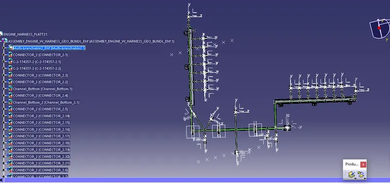
Clearance Report-
following clearances are considered-
1. Minimum Dist between 2 branch points kept more than 60 mm.
2. P clamps are positioned with positive locking with ribs on bracket.(where possible)
3. 2 firr tree clamps are provided for channel2, considering Bend of bundle on engine block.
4. slack is provided to those branches in channel, where sub branches are connecting to other connectors than ijector connectors.
5. For connectors on Ejectors, being a very high temp. zone, channels are provided.
Some important packaging rules and best practices to be considered during wire harness routing and placing of the clips and clamps are as follows –
- Distance between two clamps on a straight branch should be maximum of 200mm.
- The minimum branch length should be 50mm.
- Minimum distance between clip and nearest branching point should be 25mm.
- The minimum distance between two straight connection points should be 200mm.
- The minimum distance between two breakout points should be 50mm.
- To limit the number of branches from a single branch point to 4.
- Enough clips clamps shall be provided to ensure positive clearance with surroundings and safety of wiring harness.
- Fir tree clips and other clips can be added to the Geometric bundle as they are electrically defined and are part of the Wire harness routing and should be provided with the Wire bundle package.
- Enough slack should be provided to the wiring harness which help not to get damaged during the opening and closing of Back Door.
- Easy manufacturing, installation, removal and maintenance have to be considered while designing the wire harness.
- The wire routing should be done keeping in mind the cost effectiveness of the bundle package.
- To avoid the harness routing and clipping in blind zones of the operator during the assembly and the service.
- To provide proper slack at end connectors so that there will be no tension on the wire bundle.
- To avoid sharp edges on the sheet metal parts and if it is not possible then provide protection parts to prevent damage of the wire bundle.
- Routing through small structural holes and openings shall be avoided. To minimize chaffing and handling of the wiring harness during installation.
- To provide separate branch points for separate connectors to ensure Poka-Yoke.
- The bend ratio for all the bundle segment is considered to be 1.4 to 1.5.
clipping-
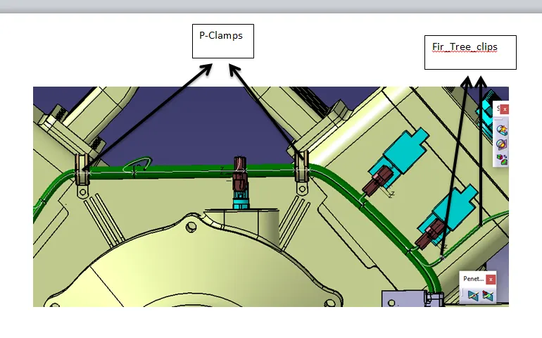
2 P clamps and 3 fir tree clamps are used.
Position for P clamp- 2 clamps are Near Inter connection Point connector.
Placed on the bolts of bracket.
1 Fir tree clip is used for passing Bundle to Cnannel 1.
2 fir clips are used to pass bundle from Inter connection Point connector to Channel2.
Harness Continuity-
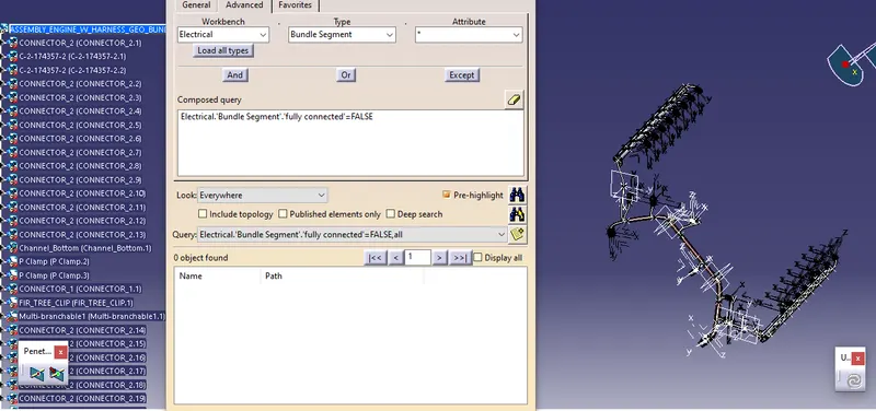
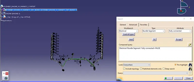
Flatten Assembly-
NOTE- May be due to software glitch, flattening the assembly was creating errors with fir tree clips.
hence for flattening purpose, fir tree clips are m=eliminated in routing here.
Drawing for the same is created and submitted with the folder .rar file.
Following Workbeches are used as per requirement to complete the project-
Mechanical Assembly- for fixing ideal location of components.
Electrical Part WB- for defining parts as electrical part.
Electrical Harness Assembly- for creating routing
Electrical Flattening Assembly- For Flattening routing
Drawing- to create 2d representation 0f the flatten assembly.