Planetary Gear
PROJECT REPORT ON MOTION ANALYSIS OF PLANETARY GEAR
Objective
- To calculate pitch circle diameter and number of teeth for the planet gear.
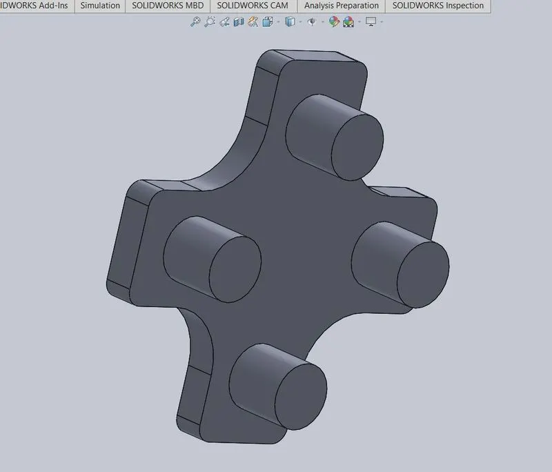
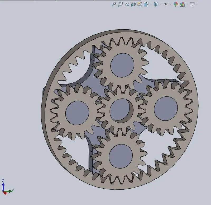
- To make the 3D assembly of planetary gearing which consists of sun gear, four planet gears, ring gear and the carrier.
- To perform the motion analysis on the given 3D assembly.
Theory
Planetary gears are at the heart of modern engineering and are used in gearboxes that power everything from basic plant machinery to cutting-edge electric vehicles. The simple configuration of a central drive and orbiting gears was developed thousands of years ago to model the movements of the planets.
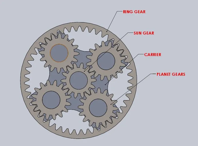
A simple planetary gear set is made up of three main components:
1. The sun gear that sits in the centre (central gear).
2. Multiple planet gears.
3. The ring gear (outer gear).
The load from the sun gear is distributed to several planetary gears which can either be used to drive an outer ring or a shaft or spindle. The central sun gear takes a high-speed, low-torque input. It drives several rotating external gears which increases the torque.
Design parameters of the gears
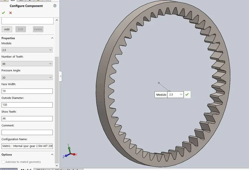
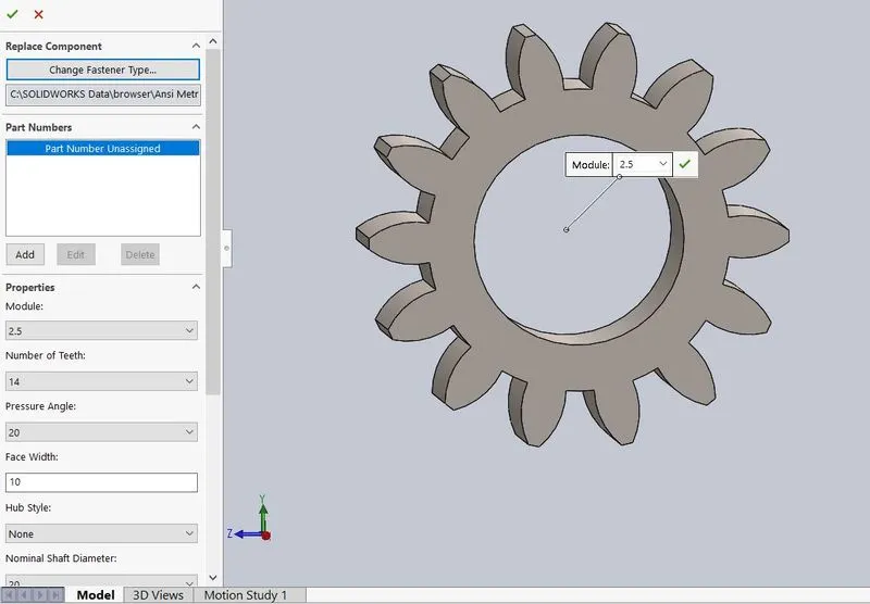
| Sl.No | PARAMETERS | RING GEAR | SUN GEAR |
| 1 | Module | 2.5 | 2.5 |
| 2 | Number of teeth | 46 | 14 |
| 3 | Pitch diameter | 46*2.5=115 mm | 14*2.5=35 mm |
| 4 | Pressure angle | 20 | 20 |
| 5 | Face width | 10 mm | 10 mm |
| 6 | Outside diameter | 130mm | NIL |
| 7 | Shaft diameter | NIL | 20 mm |
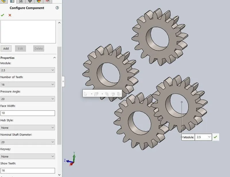
- To calculate the planet gear parameters:
Let the pitch circle diameter of the planet gear be x.
i.e (Pitch circle dia of ring gear)/2=(Pitch circle dia of sun gear)/2 + Pitch circle dia of planet gear
or (115/2) = (35/2) + x
x = 40 mm
Therefore, the pitch circle diameter of planet gear = 40 mm
Module = 2.5
Hence, the number of teeth = 40/2.5 = 16
Procedure
- Import the internal and external spur gears from the Toolbox> ANSI metric system. For sun gear and planet gear, import external spur gear and for ring gear import internal spur gears by following the gear specifications so that module remains same.
a) Ring gear
b) Sun gear
c) Planet gear
- Now draw the 3d model of the carrier as shown below:
- Make the required assembly by restricting the carrier in one degree of freedom which is rotational followed by constraining the remaining ring, sun and planet gears.
- Now perform the motion analysis on the assembly as per the given conditions and plot the graph of angular velocity of the output against time.
Motion Analysis
Given conditions:
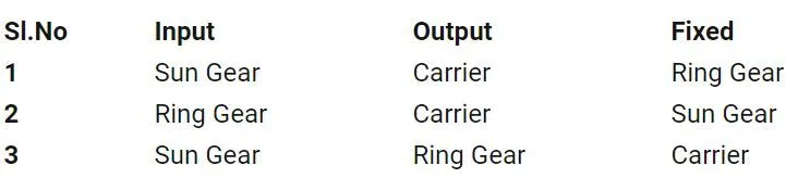
The motor input is varied between sun gear and ring gear as per the above cases and the motor rpm is set at 200 rpm.
CASE 1
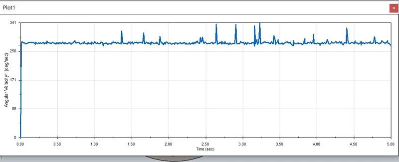
- Motor input is given to sun gear and ring gear is fixed.
- Video: https://drive.google.com/file/d/1UnJJjmOHJz0fmQQdhOx4DI6qnciVwjmc/view?usp=sharing
- The plot of angular velocity of carrier against time:
CASE 2
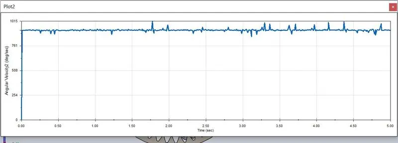
- Motor input is given to ring gear and sun gear is fixed.
- Video: https://drive.google.com/file/d/19wmRv3RQ7mJNs38pNxT73HvONcxGDujY/view?usp=sharing
- The plot of angular velocity of carrier against time:
CASE 3
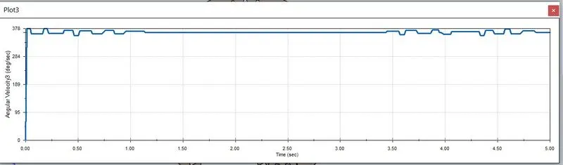
- Motor input is given to sun gear and carrier is fixed.
- Video: https://drive.google.com/file/d/1Cy2njrsXAdP4AIXhravapxhFmRrpv2O9/view?usp=sharing
- The plot of angular velocity of ring gear against time:
Part files and assembly
Link:https://drive.google.com/drive/folders/1FMckwus8UPuIcVJ50qmhZD_aQfbIlyRp?usp=sharing
Conclusion and results
- In case 1, the planet gears rotate along with the carrier inside the fixed ring gear and the angular velocity of the carrier varied between 276 deg/sec and 341 deg/sec.
- In case 2, the input is given to ring gear which rotate the planet gears along with the carrier by keeping the sun gear fixed and the angular velocity of the carrier was the highest among the three cases (1015 deg/sec).
- In case 3, the input is given to sun gear which rotate the planet gears along its own axis transmitting the motion to ring gear by keeping the carrier fixed. The angular velocity of the ring gear varied between 360 deg/sec and 378deg/sec.