MBD Simulation on IC Engine Valve Train
MBD Simulation on IC Engine Valve System Train
AIM
To carry out MBD simulation on the IC engine valve train by following two cases of cam lift.
OBJECTIVE
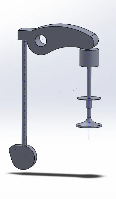
- To model cam, push rod, rocker arm, valve and valve mount using solidworks.
- To perform motion study on the assembly with a valve lift of 3.5 mm and 6 mm.
- To plot linear displacement vs time graph on both cases.
- To plot contact force between cam and push rod.
- To plot contact force between push rod and rocker arm.
- To plot contact force between rocker arm and valve.
THEORY
The main function of the valve train, as indicated by its name, is to control the opening and closing of the valves and, for older models, the fuel output of the injectors. Most of the heavy-duty diesel engines we work with are 4 valve engines, meaning there are four valves in each cylinder: 2 intakes and 2 exhaust. The valve train uses different components based on the type, push on or lift up from the valves, allowing air into and out from the cylinder. In the middle of all the valves is the injector, which will be pushed down on to inject fuel into the cylinder. All of the timing for this process is incredibly precise. Newer engines use electrical signals to cue the injector, rather than the mechanical valve train, which makes that process even more precise.
PROCEDURE
- Create the following 3d parts of the IC Engine valve train.
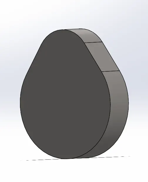
a) Cam
A cam is a rotating or sliding piece in a mechanical linkage used especially in transforming rotary motion into linear motion. It is often a part of a rotating wheel (e.g. an eccentric wheel) or shaft (e.g. a cylinder with an irregular shape) that strikes a lever at one or more points on its circular path.
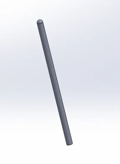
b) Push rod
A pushrod is a long, slender metal rod that is used in overhead valve engines. It’s also used to transfer motion from the camshaft in the engine block to the valves in the cylinder head. There is a lifter on the bottom end of a pushrod which gets in contact with the camshaft. Camshafts lobe moves the lifter upwards, which moves the pushrod. The top end of the lifter further pushes on the rocker arm, which opens the valve.
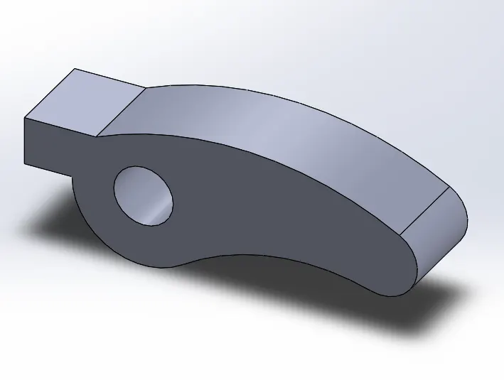
c) Rocker arm
The engine design determines the ways the valve will be actuated, either by a rocker arm, finger or bucket tappet. In an overhead camshaft engines bucket tappets or fingers are used, upon which the cam lobes contact. Rocker arms are used in overhead valve engines, which are actuated by a pushrod and pivot on a shaft. It can also be pivoted on individual ball studs which will help to actuate the valves.
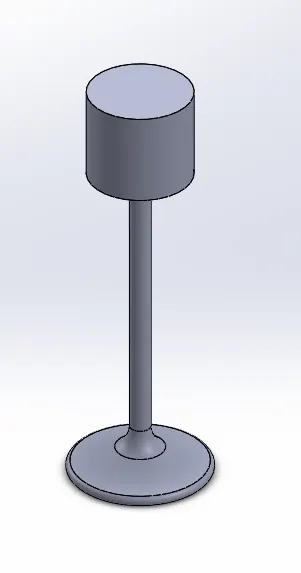
d) Valve
The valve used in most modern engines is called a poppet valve. Some valves like sleeve valve, slide valves and rotary valves are also considered at times. Generally, poppet valves are opened by the camshaft lobe or rocker arm. It’s closed by a coiled spring called a valve spring.
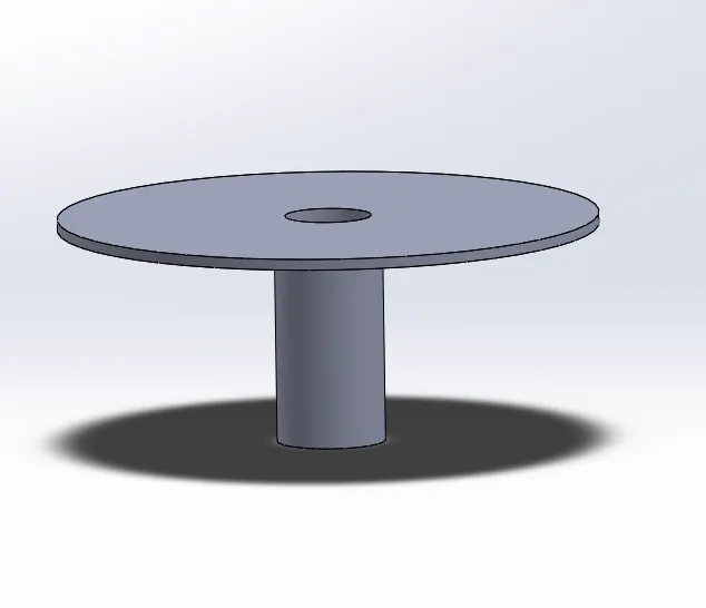
e) Valve mount
- Create an assembly from the above parts by satisfying all the constraints.
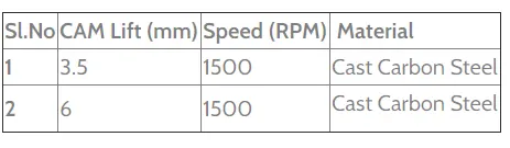
- While conducting motion study, provide the motor input 1500 rpm and let the material be cast carbon steel.
- Set all the contact and insert the spring between valve and valve mount.
- Now change the fps to 9000 fps along with precise contact.
- Now, conduct motion study on this assembly based on two cases of cam lift:
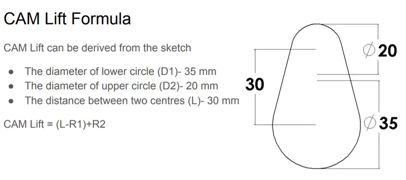
a) CASE 1
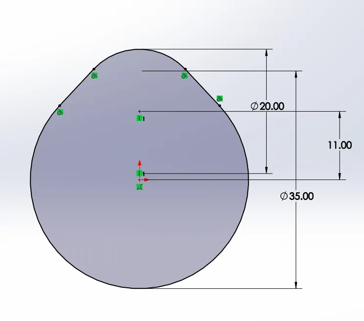
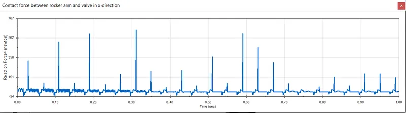
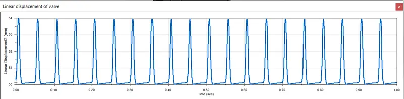
When the cam lift is 3.5 mm and motor input is 1500 rpm:
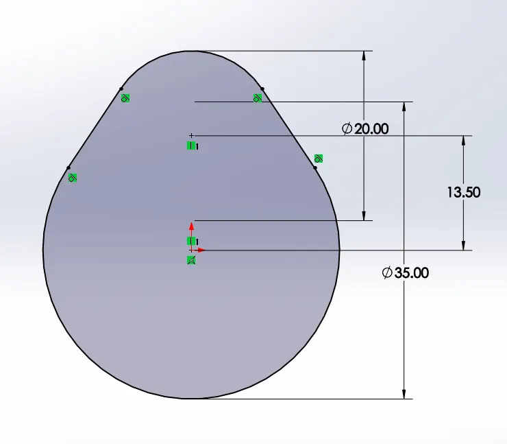
Radius of lower circle R1 = 17.5 mm
Radius of upper circle R2 = 10 mm
L = CAM LIFT - R2 + R1 = 3.5 - 10 + 17.5 = 11 mm
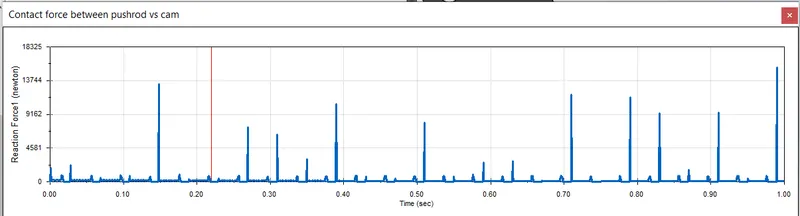
Contact force plots obtained after motion study:
1) Contact force between cam and push rod
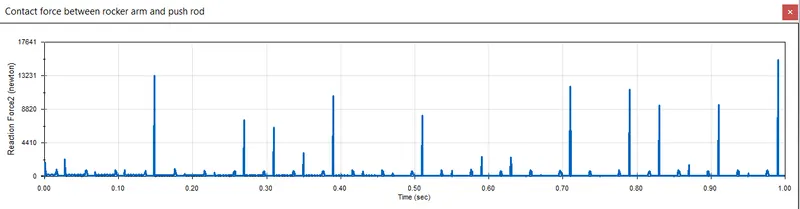
2) Contact force between rocker arm and push rod
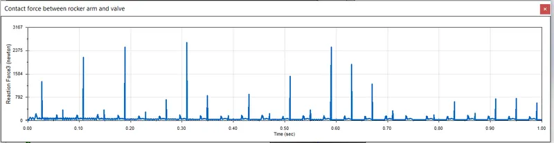
3) Contact force between rocker arm and valve(magnitude)
4) Contact force between rocker arm and valve(X-direction)
5) Linear displacement of valve
a) CASE 2
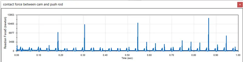
When the cam lift is 6 mm and motor input is 1500 rpm:
Radius of lower circle R1 = 17.5 mm
Radius of upper circle R2 = 10 mm
L = CAM LIFT - R2 + R1 = 6 - 10 + 17.5 = 13.5 mm
Contact force plots obtained after motion study:
1) Contact force between cam and push rod
2) Contact force between rocker arm and push rod
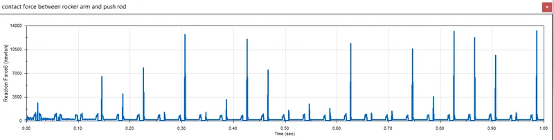
3) Contact force between rocker arm and valve(magnitude)
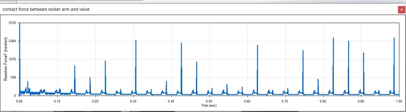
4) Contact force between rocker arm and valve(X-direction)
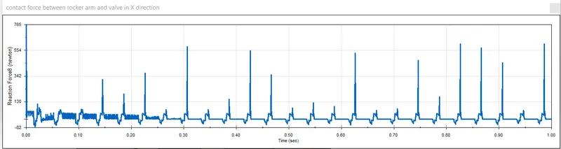
5) Linear displacement of valve
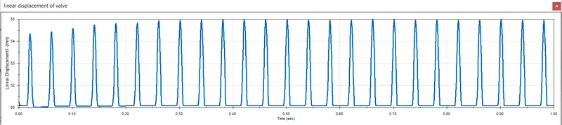
CONCLUSION AND RESULTS
- With the cam lift magnitude of the linear displacement of the valve increases.
- The magnitude represent the total contact force between two parts while the contact force in x- direction is the frictional force between as the rocker arm is sliding over the valve.
- Height of the valve depend son the composition of the cam.