Internal Geneva Mechanism
AIM
To create a 3d assembly of internal geneva mechanism using SolidWorks and to conduct motion analysis under motor rpm of 10 and 20 and then post processing it.
OBJECTIVE
i) To create the 3D model from the 2D part drawing using solidworks.
ii) To create the assembly of internal geneva mechanism.
iii) To conduct motion analsyis on the chosen assembly under motor rpm of 10 (60 fps) and 20 (120fps)
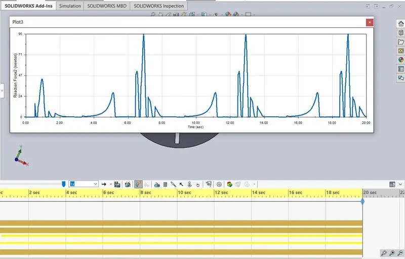
iv) Plot the graph for contact force between the driver and driven wheel with and without precision.
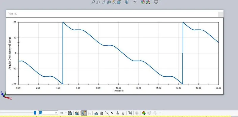
v) Plot the graph for angular displacement of the driver wheel.
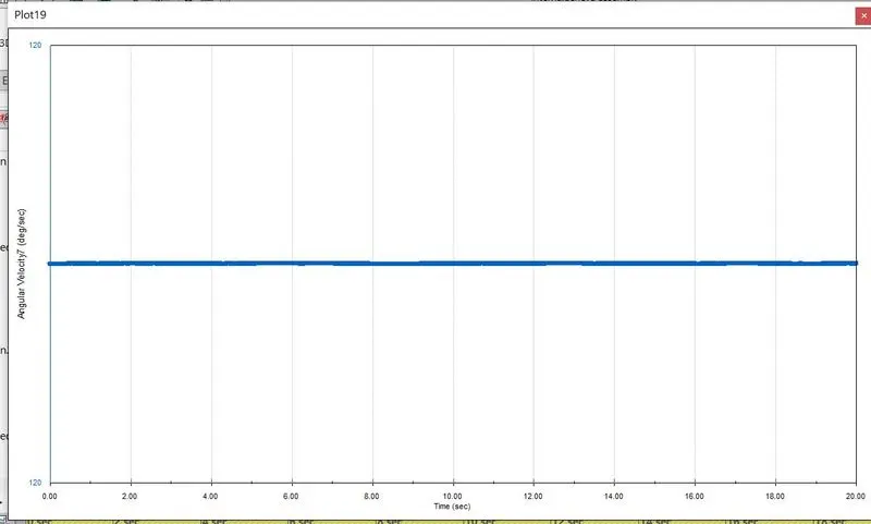
vi) Plot the graph for angular velocity of the driver wheel.
THEORY
- The geneva is one of the earliest of all intermittent motion mechanisms and it is commonly known as maltese cross mechanism. The geneva mechanism translate a continuous rotation into an intermittent rotary momtion.
- In the most common arrangement, the driven wheel has four slots and this advances by one step of 90 degrees for each rotation of the drive wheel.
- The rotating drive wheel has a pin that reaches into a slot of the driven wheel advancing it by one step. The drive wheel also has a raised circular blocking disc that locks the driven wheel in position between steps.
Internal Geneva Mechanism
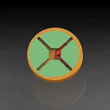
An internal Geneva drive is a variant on the design. The axis of the drive wheel of the internal drive can have a bearing only on one side. The angle by which the drive wheel has to rotate to effect one step rotation of the driven wheel is always smaller than 180° in an external Geneva drive and always greater than 180° in an internal one, where the switch time is therefore greater than the time the driven wheel stands still.
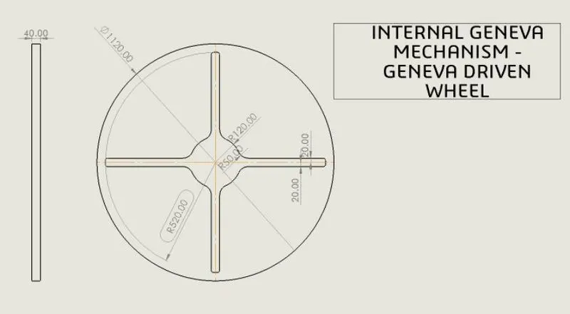
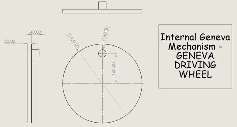
GIVEN 2D DRAWINGS
PROCEDURE
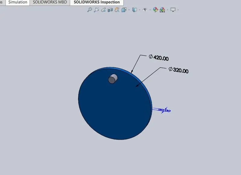
A) Initially create the 2D models of driver and driven wheels using solidworks part drawing as shown in the figure below:
DRIVER WHEEL
DRIVEN WHEEL
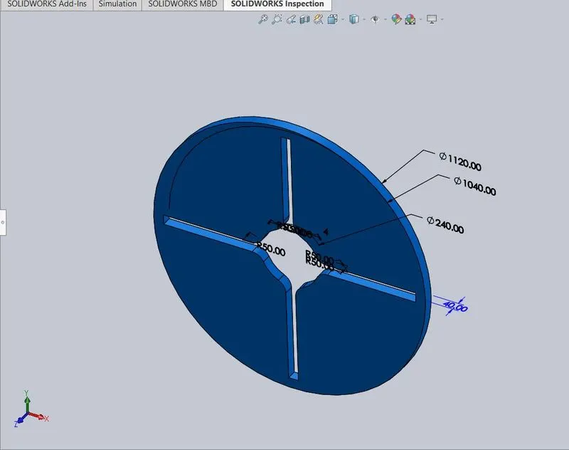
B) Now form the assembly of the two 3D parts with proper constraints:
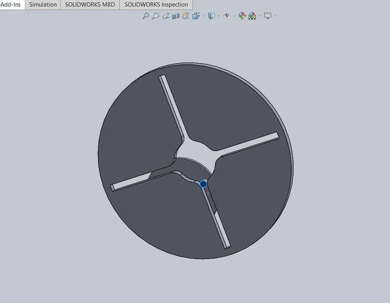
c) After the assembly carry the motion analysis on the drawn assembly.
d) Set the motor rpm to 10 for the first case and 20 for the second case.
e) Under motor rpm 10 and 60 fps, plot graph for contact force between driver and driven wheel with and without precision.
f) Then plot the graph for angular displacement of the driven wheel and angular velocity of the driver wheel.
e) Similarly repeat the steps for motor rpm 20 and 120 fps.
PLOT RESULTS
CASE 1 (10 RPM )
A) Contact force between driver and driven wheel without precision: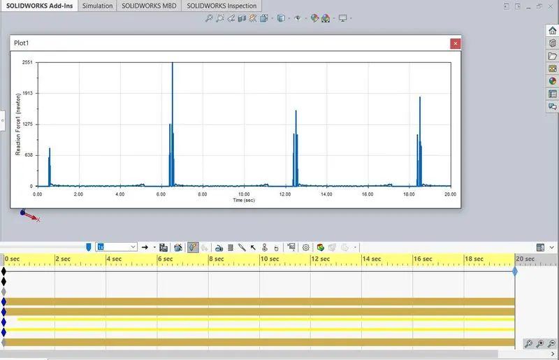
B) Contact force between driver and driven wheel with precision:
C) Angular displacement of the driven wheel:
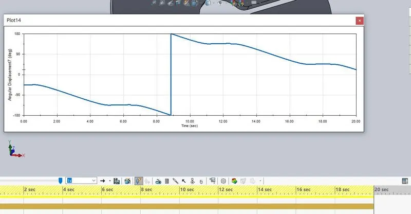
D) Angular velocity of the driver wheel:
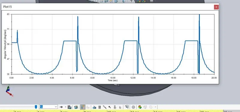
CASE 2 (20 RPM)
A) Contact force between driver and driven wheel without precision:
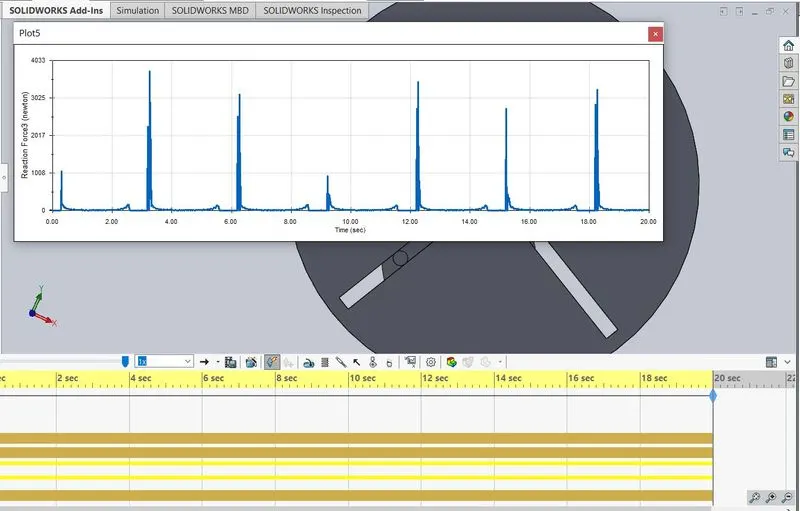
B) Contact force between driver and driven wheel with precision:
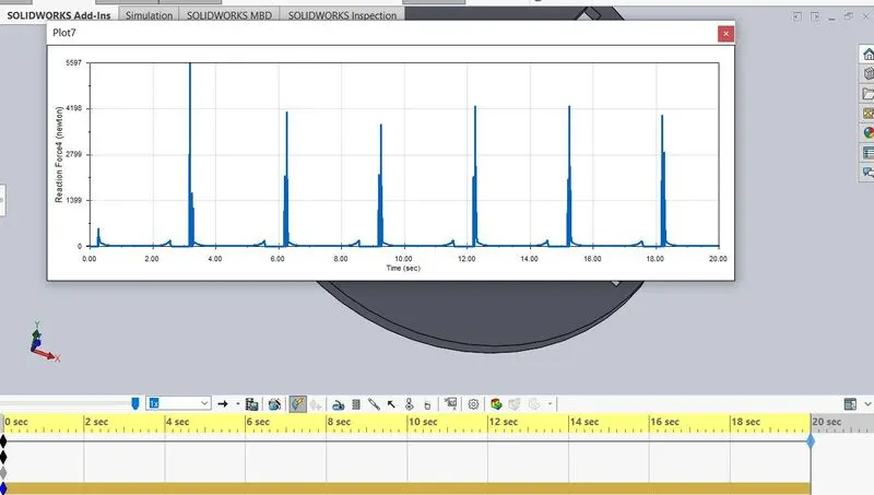
C) Angular displacement of the driven wheel:
D) Angular velocity of the driver wheel:
- Comparing the precision contact force we can see sudden surge and fall in the contact force with respect to time.
VIDEOS
10 RPM
https://drive.google.com/file/d/1uR79RYCFhG1sOzx4EXBac1PjeRY-D7aH/view?usp=sharing
20 RPM (120 FPS)
https://drive.google.com/file/d/1crJqadpF4PyWJIwUKNG28I1ZauhuS54p/view?usp=sharing
CONCLUSION
The internal geneva mechanism is created using solidworks and the motion analysis were performed as per the motor rpm and frame rate attributes.