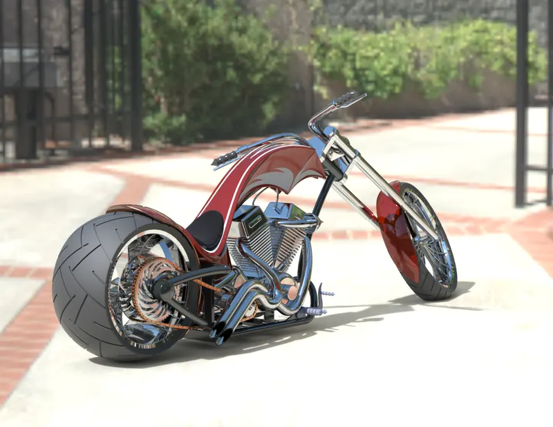
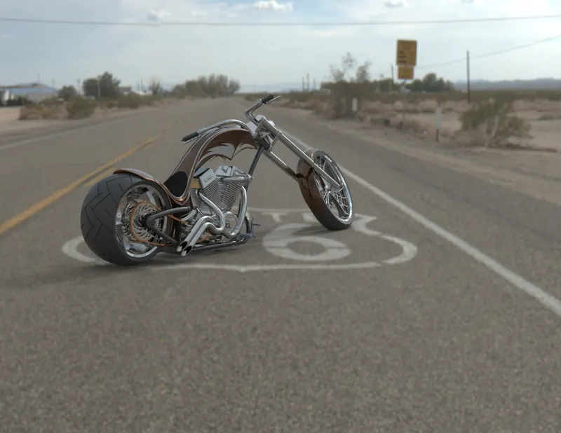
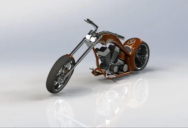
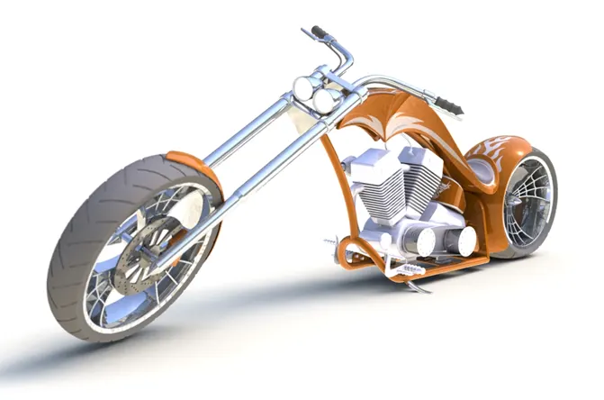
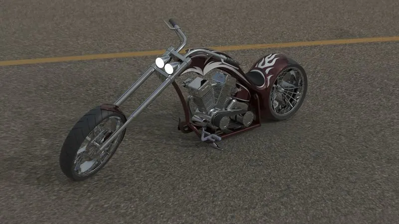
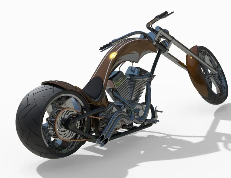
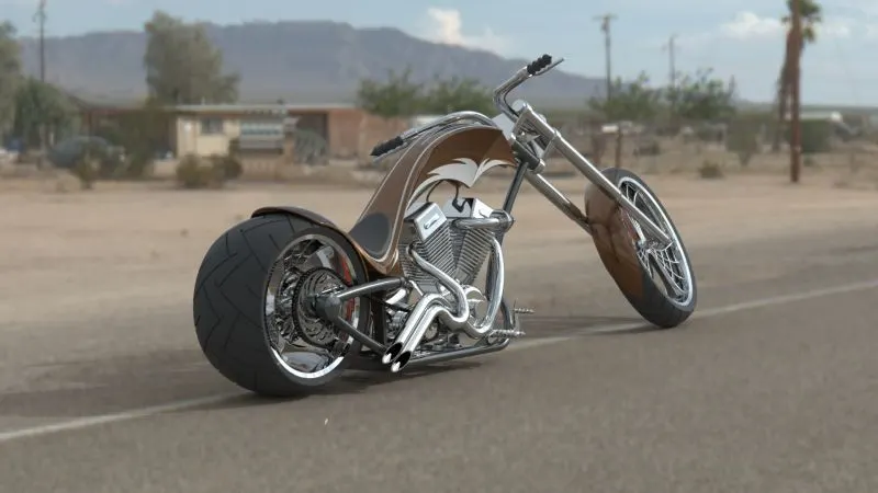
Photo Realistic Rendering
REPORT ON ASSEMBLY OF CHOPPER MODEL
DESIGN OF AMERICAN CHOPPER USING SOLIDWORKS
OBJECTIVE: - To Design, Assemble and Render the AMERICAN CHOPPER with the help of solidworks
INTRODUCTION: - SolidWorks is a solid modelling computer-aided design (CAD) and computer-aided engineering (CAE) application published by Dassault Systems. With the help of solidworks we are going to design American chopper in which we create different parts separately and then assemble in assembly environment of solidworks. The final step is to create rendering of chopper in solidworks visualize and generate the final high quality rendered images.
METHODOLOGY
- Part Modelling
- Assembly
- Rendering
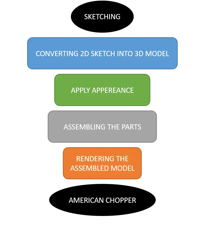
PART MODELLING
In part modelling, first the 2D sketch of the part is sketched using the tools in sketch tab and then the 2Dsketch is converted into a 3D part using features in the features tab.
FEATURES USED
Boss Extrude: This feature is used to expand the object in 3D according to sketch plane.
Extrude Cut: Extrude cut feature used to cut/remove the 3d object in linear path according to sketch.
Fillet: Fillet is a feature used for making round internal or external edges to avoid sharp edges and make it smooth.
Lofted Boss/Base: Lofted boss is a feature used to achieve Complex Shapes. It does this by interpolating surfaces between various cross-sections of a model. These cross-sections can be sketches, faces, or edges.
Split: Split tool is used to split single solid part into two solid parts. It is used to project an entity onto other surfaces or curved/planar faces.
Dome: Dome is a feature used to make dome shaped extrude including elliptical dome.
Shell: Shell feature is used to make to hollow space in solid part by selecting outer wall of the solid part and so removes the inner parts. It is also used to reduce the specific thickness.
Combine: Combine tool is used to make integration of two solid parts which intersect each other as same solid part.
Chamfer: Chamfer is used to make a sharp edge or corner slightly tapered rather than being a perfect square.
Linear Pattern: The linear parent is used to create a different number of instances required to create the pattern linearly.
Curve Driven Pattern: Curve driven pattern is used to make any pattern which followed by the curve is sketched before.
Circular pattern: Circular pattern is a feature used to make 3d feature into circular pattern according to number of insistences.
Revolve boss base: Revolve feature is used to make cylindrical or circular 3D extrude along with a given reference axis as per drawn sketch.
Revolve cut: Revolve cut is used to cut or reduce the extrude of cylindrical round surface.
Move/copy body: This feature is used to move/copy the 3D body to one place to another
Sweep: This feature is used to sweep any kind of fully defined sketch along with the path.
Sweep cut: Sweep cut is same as sweep feature but its directly proportional to sweep which makes a cut along with the sweep path.
Swept Surface: It is used to make a surface along with a path the curve is driven.
Boundary Surface: Boundary surface is used to make a surface in between two finished surfaces.
Loft Surface: Loft surface is used to make loft in between two profiles along with guide path.
Knit surface: Knit surface is used to knit the two free edges or open edges of the surfaces together also it reduces the gap between the two edges of the surface.
Surface Trim: Primarily used to cut away material from a surface, and provides two modes: Standard and Mutual.
Projection Curve: Projection curve is a 3D curve which is projected on the basis of the two different 2D curves in two different planes.
Blocks: You can make save, edit and insert blocks from the drawing items and sketch entities that you use often such as standard notes, title blocks, label positions and so on you can attach blocks to geometry or to drawing views
Trim entities: it is used to trim the unwanted lines or extended entities in the sketch.
Appearances: An appearance defines visual properties of the model including colour and texture. Appearances do not affect
physical properties which are defined by materials. every material is a assigned a default appearance.
COMPONENTS MODELLED
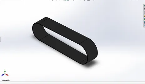
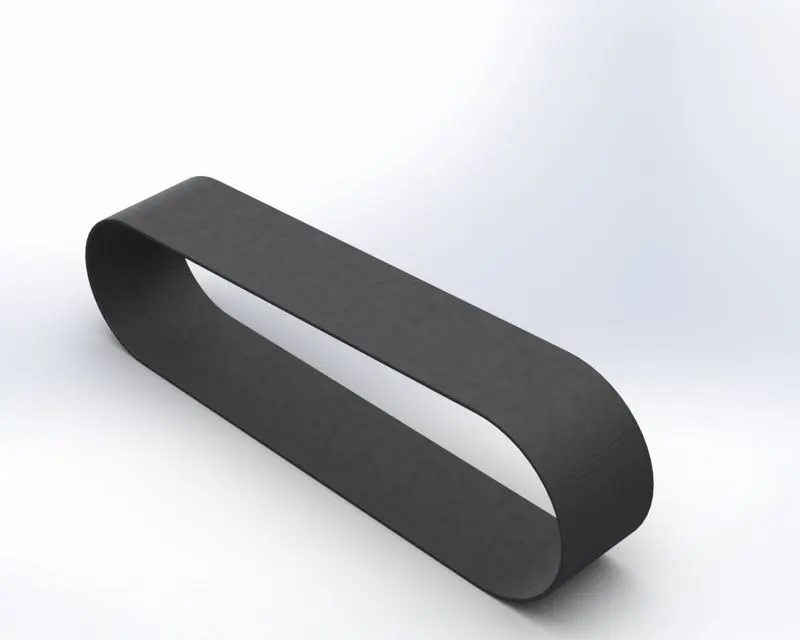
- TRANSMISSION BELT- Transmission belt is a component which is used to transmit power from one shaft/pulley to another.
-
Feature Used - Extrude and fillet.
Appearance – Matte Rubber
-
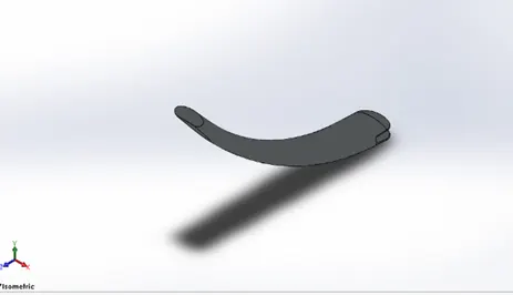
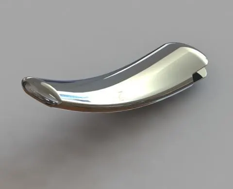
- KICK STAND – It’s a mechanical part which is used to support the chopper when it is in rest We restrict its movement to 90 degree.
Feature Used –Loft, split, dome, extrude boss, extrude cut, fillet.
Appearance – Chromium plate
-
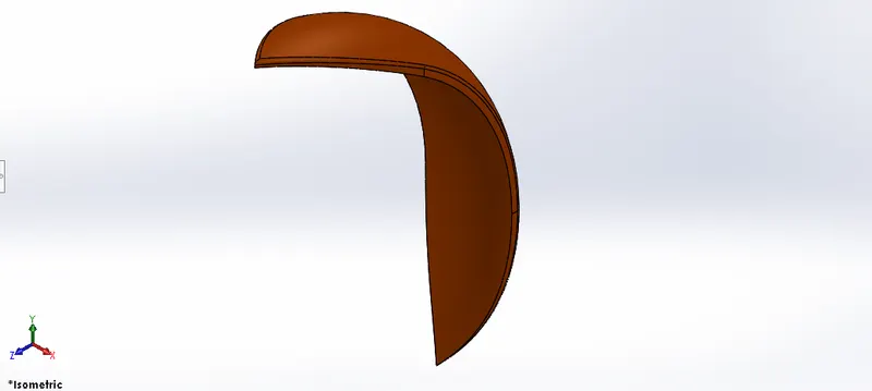
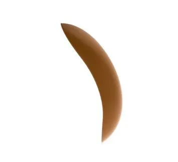
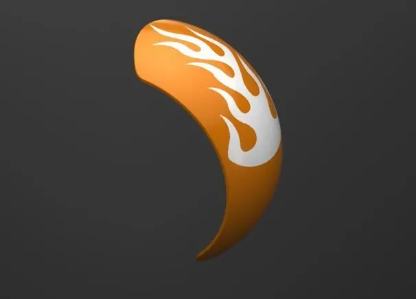
- Front Fender- Primary purpose of front fender is to cover the front wheel so that the spill over of wheel like liquids, mud, sand, rocks etc. will not come to chopper other parts and will not spoil or damage it.
Feature Used – revolve, split, dynamic mirror entity, fillet.
Appearance - painted metallic car seina
-
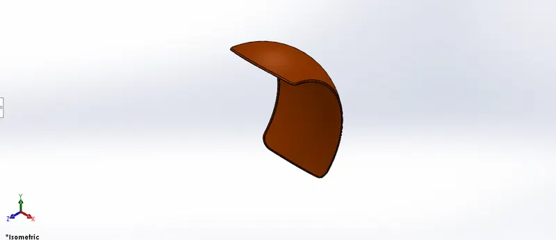
- Rear Fender- Primary purpose of rear fender is to cover the rear wheel so that the spill over of wheel like liquids, mud, sand, rocks etc. will not come to chopper other parts and will not spoil or damage it.
Feature Used – revolve, split, shell, dynamic mirror entity, fillet.
Appearance - painted metallic car seina
-
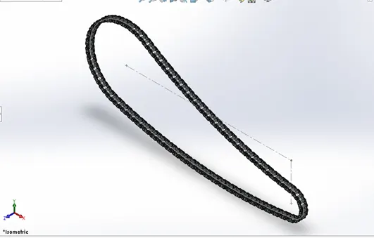
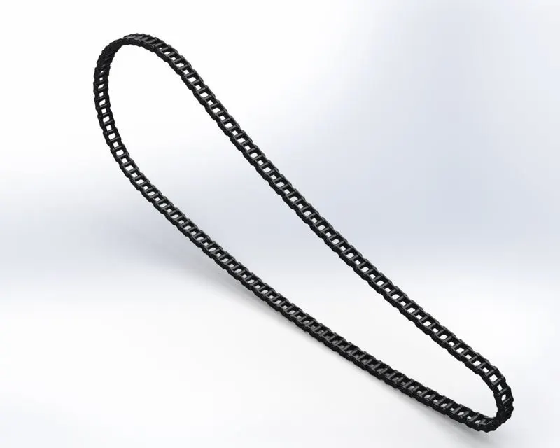
- Chain – chain is made up of several small links which are connected so that its sole purpose is to transmit power from one sprocket/gear to other.
Feature Used – Extrude boss, save and insert small block, fillet, curve driven pattern, mirror
Appearance – chromium plate.
-
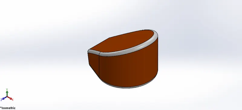
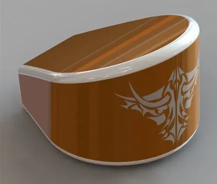
- Oil Tank – oil tank is used to store he oil for lubrication and cooling purpose of engine and its components.
Feature Used – Extrude boss, fillet, combine, shell.
Appearance – white on fillet, metallic car paint seina.
-
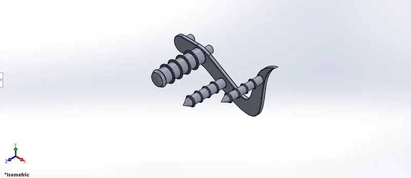
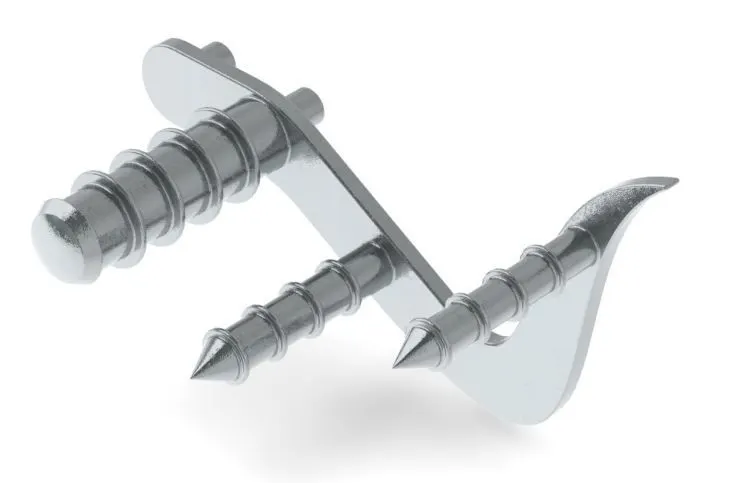
- Pedal – Its purpose is used to place the foot of rider and also used to shift the gear and apply brakes.
Feature Used – Boss, revolute, fillet, dome, chamfer, linear patern.
Appearance – chromium plate.
-
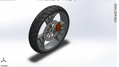
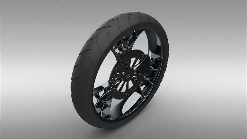
- Front Wheel- front wheel of the American chopper is made up of tyre, rim, rotor, disc.
Feature Used- Revolve Boss, Boss Extrude, Cut Extrude, Fillet, Chamfer, Mirror & Circular Pattern
Appearance- - Painted Siena for Caliper, Chrome Steel for Rim, Matte Rubber for Tire.
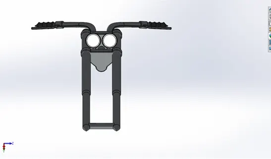
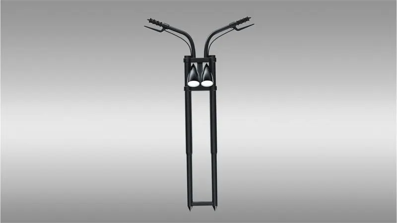
- 9. front fork- The structure which connects the chassis and the front wheel of the bike. It has various mountings on it like headlights, break wire and levers, shock absorbers etc
- Feature Used- Boss Extrude, Revolve, Sweep, Projected Curves, Composite Curves, Shell, Dome, Mirror & Linear Pattern
- Appearance:- Chrome Plate for Fork, Matte Rubber for handle and Brake Wire, and for Arial Light for Lamp.
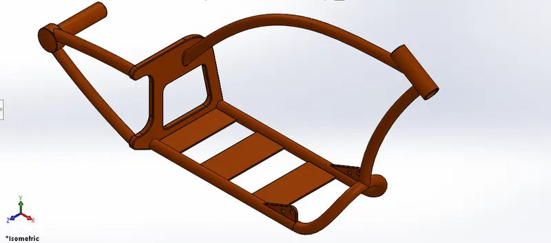
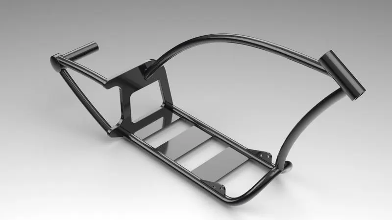
- 10.chassis- Much like a human spine and the supporting skeleton, a motorcycle chassis holds everything together - from the engine, suspension, wheels, fuel tank, handlebars, seat, airbox etc
- Feature Used- Boss Extrude, Revolve, Sweep, Mirror, Fillet, Chamfer & Projected curves
- Appearance:- Painted Siena.
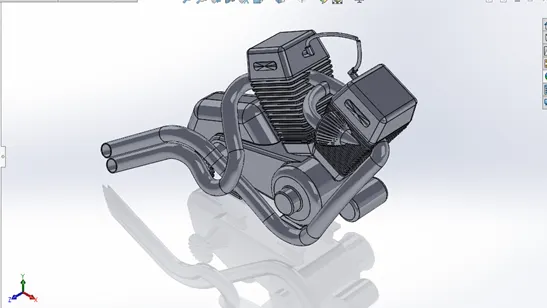
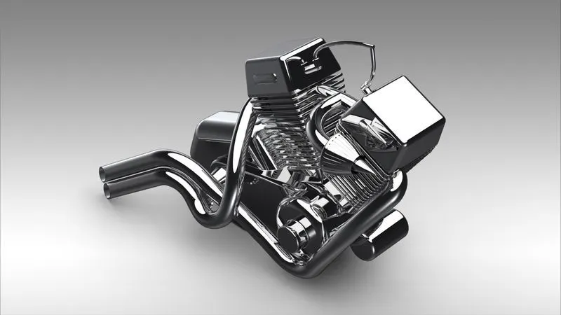
- 11.Engine- The engine, apparently known as the heart of a vehicle includes parts such as spark plug, inlet valve, outlet valve, cylinder & motor. Motorcycle engines are typically two-stroke or four-stroke internal combustion engines
- Feature Used- Boss Exrtrude, Cut Extrude, Revolve, Sweep, Projected Curves, Composite Curves, Fillet, Chamfer, Mirror ,Linear Pattern & Circular Pattern
- Appearance:- Chrome Plat
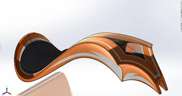
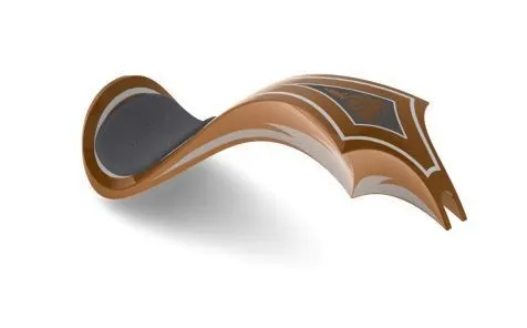
12.Gas tank-The gas tank stores the fuel required to run the engine.
Feature Used- Surface Fill, Boundary Fill, Surface Sweep, Extrude Surface & Projected Curves.
Appearance:- Painted Siena for Gas Tank and Fabric for Driver Seat.
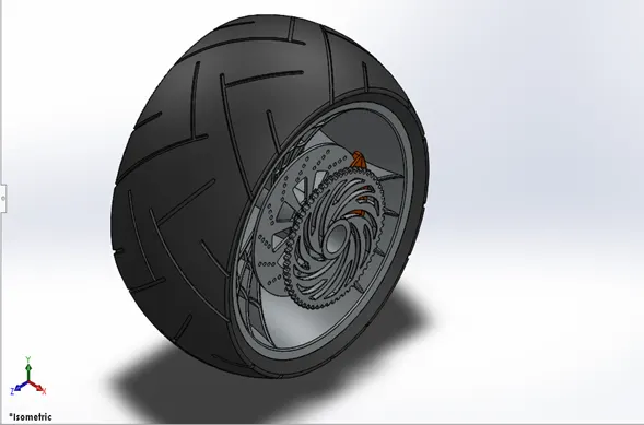
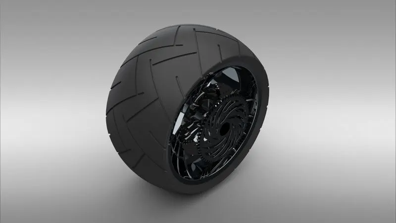
13.Rear Wheel:-The rear Wheel is much thicker than the front wheel. Just like the front wheel, it is also designed to bea multi-body part consisting of the rotor, sprocket, rim, tire, and the calliper all in a single part.
Feature Used- Fillet, Revolve Boss/Base, Chamfer, Extruded Boss/Base, Revolve Cut, Circular Pattern, Linear Pattern, and Mirror.
Appearance:- Painted Siena for Caliper, Chrome Steel for Rim, Matte Rubber for Tire.
ASSEMBLY OF AMERICAN CHOPPER
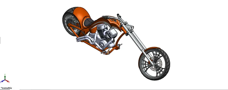
All the parts were assembled in a Solidworks Assembly file by inserting each part, one after the other using suitable mate
relations.
Mates: Mates create geometric relationships between assembly components. As you add mates, you define the allowable
directions of linear or rotational motion of the components. You can move a component within its degrees of freedom, visualizing the assembly's behavior. Some of the mates used during the assembly process are
- Anglemate
- Reference Entity for Angle Mates
- Coincident Mate
- Concentric Mate
- Distance Mate
- Lock Mate
- Parallel and Perpendicular Mates
- Tangent Mate
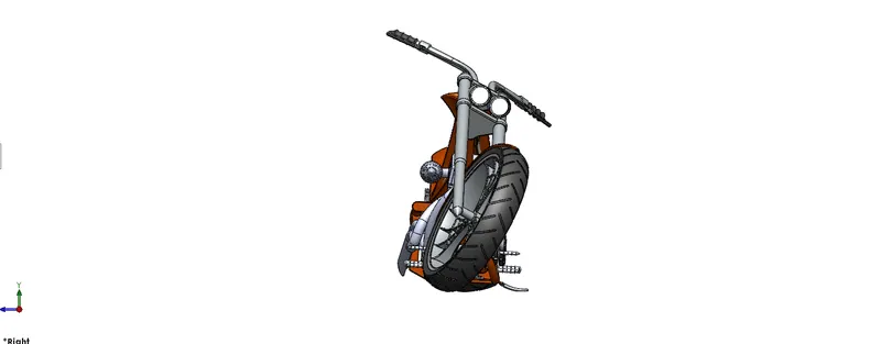
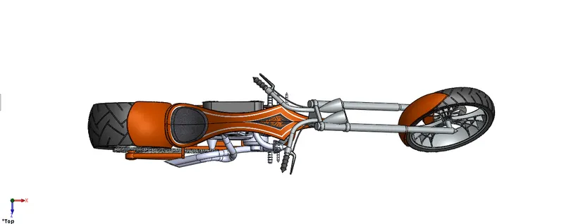
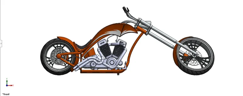
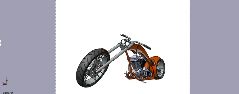
RENDERING PROCESS:-
Rendering is process of creating realistic images of the model with environment. In rendering various aspects such as camera, light, environment, background scene, appearance, etc. are taken in consideration before final rendering. To check the all thing preview rendering option is used.
There are two ways of rendering in SOLIDWORKS.
1. Photoview 360
2. Solidworks VisualizeS
SOLIDWORKS Visualize allows you to leverage your 3D CAD data to create photo-quality content in the fastest and easiest way youcan from images to animations, interactive web content, and immersive Virtual Reality. Bring your products to life.
Step_1:- Import the assembly file into the Solidworks Photo Visualize.
Step_2:- Give the appearance to parts to make it more realistic.
Step_3:- Add Scenes as the background
Step_4:- Make a fast Rendering and check the output
CONCULSION
In end of this American chooper project learn to use a new features and tools And learn about assembly according to planes of models including advanced mates Finally learning about Light, environment setup , colour , Decals , Back plates
Using Photo view 360 and solid works Visualize.