Photo Realistic Rendering
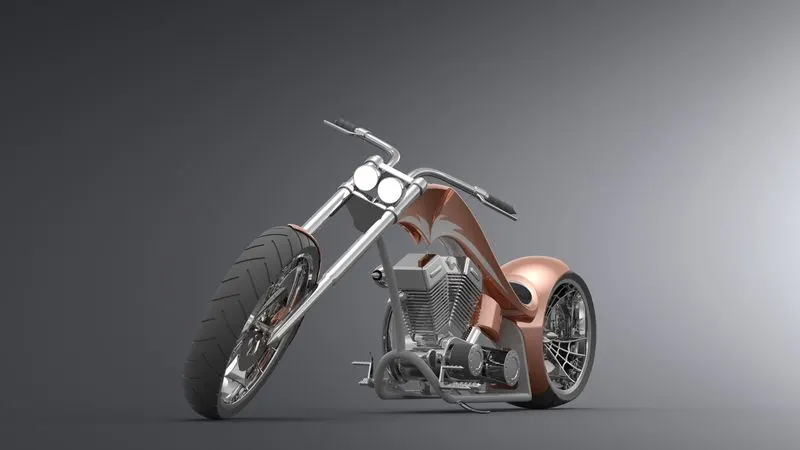 A REPORT ON
DESIGNING AN AMERICAN CHOPPER USING SOLIDWORKS
Etikala Surajkumar
Mechanical
OBJECTIVE
The main objective of this project is to Design a 3D model of an AMERICAN CHOPPER using SOLIDWORKS and produce photo realistic rendering images using SOLIDWORKS VISUALISE
INTRODUCTION
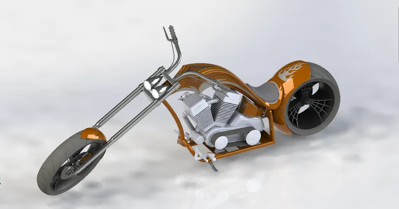
In 3D computer graphics, 3D modeling is the process of developing a mathematical coordinate-based representation of any surface of an object in three dimensions via specialized software. The product is called a 3D model. Someone who works with 3D models may be referred to as a 3D artist or a 3D modeler. A 3D Model can also be displayed as a two-dimensional image through a process called 3D rendering or used in a computer simulation of physical phenomena. The 3D model can be physically created using 3D printing devices that form 2D layers of the model with three-dimensional material, one layer at a time. In terms of game development, 3D modeling is merely a stage in the entire development process.
DESIGN METHODOLOGY
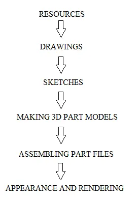
RESOURCES
Here we focus on CAD (Computer Aided Design) software for mechanical objects. The software can be highly specific, it is designed to be a technical tool with functions in industrial design, mechanical design, architecture, and areas such as aerospace engineering and astronautics. A CAD model will contain data like material properties, dimensions, tolerance and manufacturing process specific information. Furthermore, many CAD applications now offer advanced rendering and animation capabilities to better visualize product design.
There are many platforms to make 3D design models, such as
01-Solidworks
02-TinkerCAD
03-FreeCAD
04-BlocksCAD
05-Creo
06-Fusion 360°
07-AutoCAD
08-CATIA
09-OpenSCAD
10-Rhino
Here we are using Solidworks to design the American chopper
SOLIDWORKS
Published by Dassault Systemes, it is often used by professional 3D designers. It is a parametric featured-based model. The software includes a wide range of features such as design validation tools, or reverse engineering. It tends to be used for industrial objects. It is quite practical and detailed. One of its special features is that unlike many other software that mimic curves through gently inclining flat structures, Solidworks uses a system of NURBS. This system allows to create very detailed curvatures. Also, instead of polygonal modeling, it uses dimensional sketching so that resizing becomes far less of a hassle. One disadvantage that is often brought up by users of the software is the limited ability to import .STL files. If you wish to download and edit .STL files, a secondary program will most likely be necessary. The file format is very much an output file format and not intended for post-design processing.
DRAWINGS
Get the required drawings of the 3D Model.
Now these 2D drawings will be help full to create the sketches and 3D models. These 2D drawings should have the all the dimensions in it, so that the sketches created on CAD software will be fully constrained.
SKETCHES:
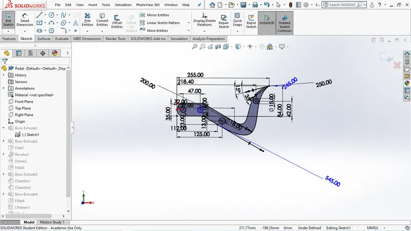
Sketches are the 2D geometries of the parts to be modeled, the user draws a shape in the workspace using a mouse or a tablet. The system then interprets this shape as a 3D object. Users can then alter the object by cutting off or adding sections. The process of adding sections to a model is generally referred to as overdrawing. The user is never required to interact directly with the vertices or NURBS control points.
3D PART MODELS
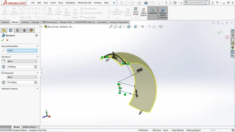
This is the next step post sketches, here the 2D sketches which are created in the space of the CAD software are converted into 3D parts by using different types of tools available in that software
ASSEMBLING PART FILES
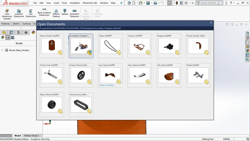
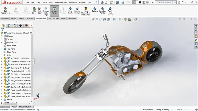 All the 3D part files are assembled with perfect mates
APPEARANCE AND RENDERING
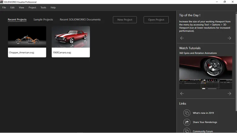
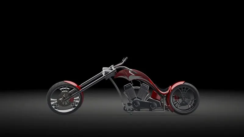
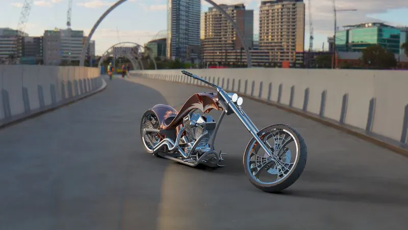
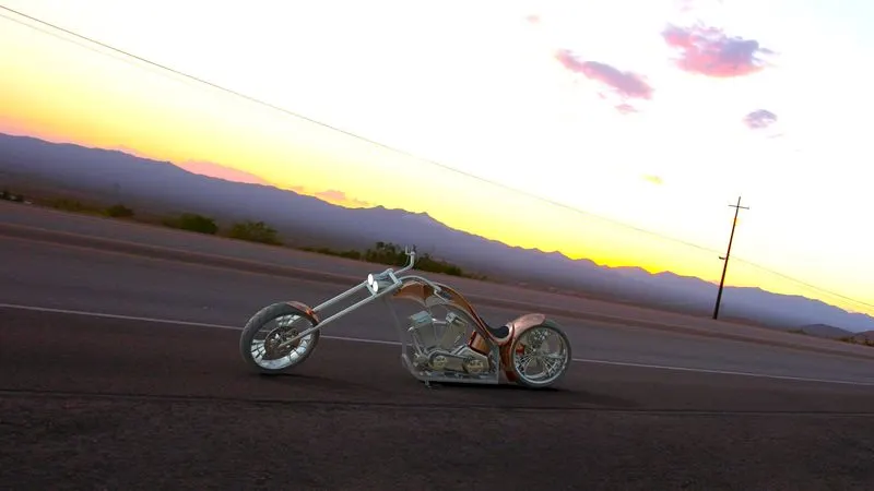
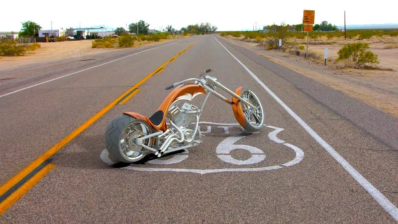
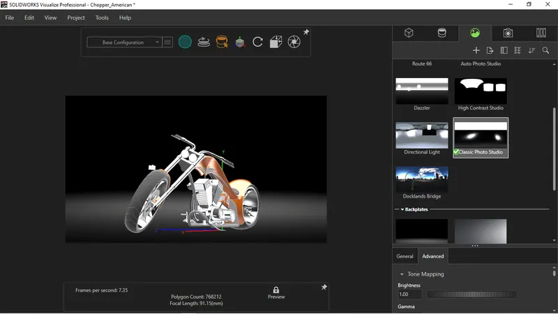 The RENDERING final step after the assembling of all the part files, it is done in another application on SOLIDWORKS i.e... SOLIDWORKS Visualize
In this the assembled American chopper is rendered in a realistic background and with realistic HDR environment.
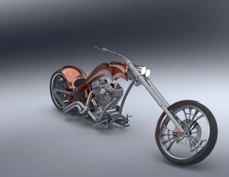
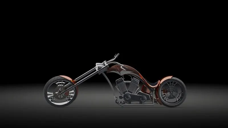 FINAL RENDERED IMAGE OF AMERICAN CHOPPER
DESCRIPTION
TYPES OF FEATURES
SKETCH:
⦁ A sketch is a 2D profile or cross section. To create a 2D sketch, you use a plane or a planar face. In addition to 2D sketches, you can also create 3D sketches that include a Z axis, as well as the X and Y axes.There are various ways of creating a sketch.
OFFSET:
⦁ Offset one or more sketch entities, selected model edges, or model faces by a specified distance. For example, you can offset sketch entities such as splines or arcs, sets of model edges, loops, and so on.
FILLET:
⦁ It creates a rounded internal or external face on the part. It can fillet all edges of a face, selected sets of faces, selected edges, or edge loops.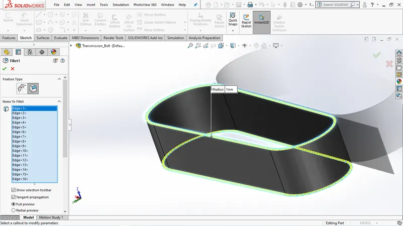
EXTRUDE BOSS/BASS:
⦁ Extruded Boss feature adds material to the part model.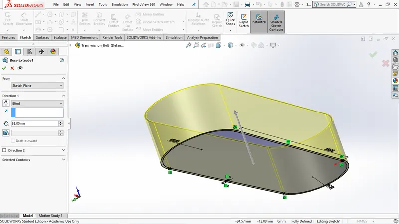
EXTRUDE CUT:
⦁ Extrude cut is another feature which helps to remove materials from the 3D model. It is just opposite to extrude boss/base feature, because it cuts a sketch profile while extruding. You can cut in both directions and mainly used for creating holes, channels, slots etc.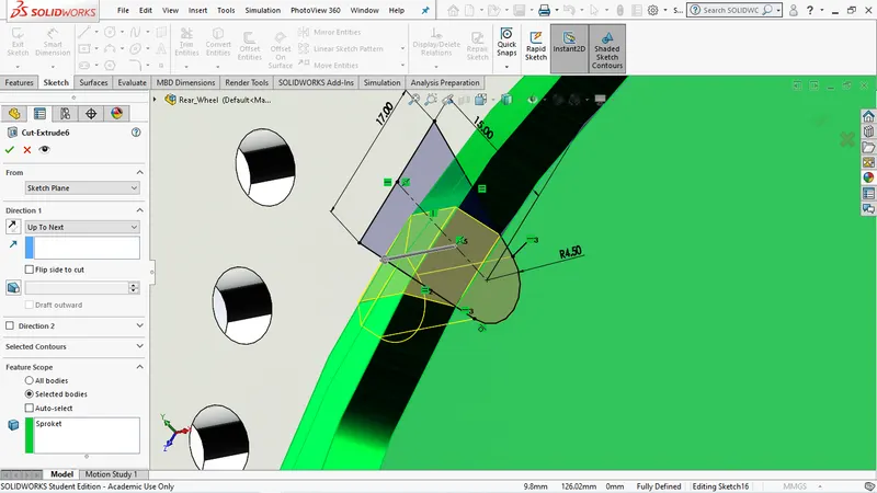
LOFTED BOSS/BASS:
⦁ creates a feature by making transitions between profiles. A loft can be a base, boss, cut, or surface. You create a loft using two or more profiles. Only the first, last, or first and last profiles can be points. All sketch entities, including guide curves and profiles, can be contained in a single 3D sketch.
DOME:
⦁ Dome is on the Features toolbar, or click Insert > Features > Dome. ... Click Direction, and select a direction vector from the graphics area to extrude the dome in a direction other than normal to the face. As a direction vector, you can use a linear edge or the vector created by two sketch points.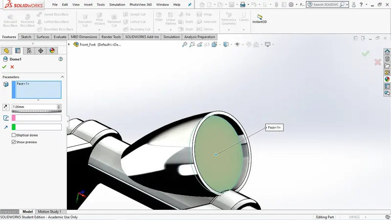
SPLIT:
⦁ Split tool is used to project an entity sketch, solid, surface, face, plane, or surface spline onto other surfaces or curved/planar faces. We can split faces on multiple bodies with one command.
TRIM ENTITES:
⦁ Trim multiple, adjacent sketch entities by dragging the pointer across each sketch entity.
SHELLS:
⦁ The shell tool hollows out a part, leaves open the faces you select, and creates thin walled features on the remaining faces.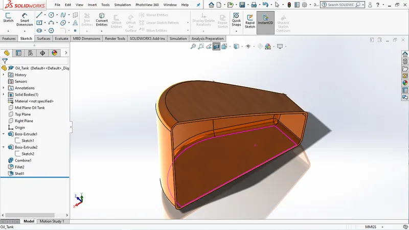
REVOLVE:
⦁ Revolves add or remove material by revolving one or more profiles around a centerline. You can create revolved boss/bases, revolved cuts, or revolved surfaces. The revolve feature can be a solid, a thin feature, or a surface.
DYNAMIC MIRROR:
⦁ This tool allows the user to mirror a sketch about a line while creating the sketch.
APEARANCES:
⦁ This method gives you the choice of applying an appearance to a face, feature, body, part or component. It is sometimes required to apply and edit an appearance's properties to change a parameter such as colour, transparency, or reflectivity.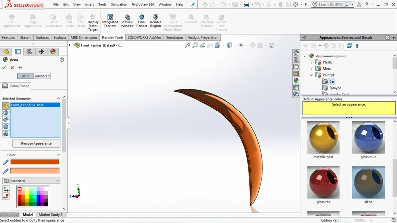
COMBINE:
⦁ The combine option of the Base Flange/Tab command lets you merge bodies with coplanar faces. To combine sheet metal bodies by adding a base flange in a multibody sheet metal part, move the bodies to be merged to the same plane.
CHAMFER:
⦁ The chamfer tool creates a beveled feature on selected edges, faces, or a vertex. Set the Distance and Angle in the Chamfer Property Manager. A manipulator arrow appears that points in the direction in which the distance is measured.
CIRCULAR PATTERN:
⦁ Circular patterns are used to create multiple instances of one or more features that you can space uniformly around an axis. Pattern instances inherit the feature color of the original feature when the pattern is based on one feature.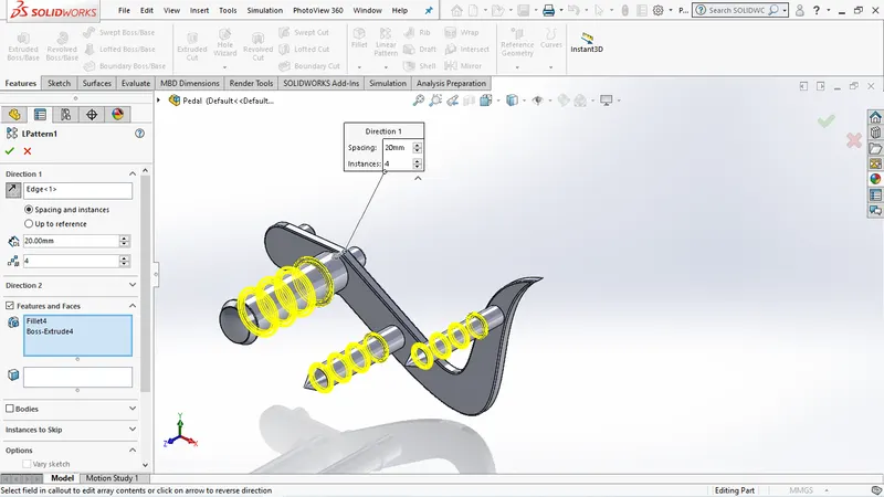
LINEAR PATTERN:
⦁ Linear pattern is used to create multiple instances of one or more features that you can space uniformly along one or two linear paths. To create a linear pattern create one or more features to replicate.
SURFACE MODELING:
⦁ Surface Modeling is the method of showing or presenting solid objects. The process requires you to convert between different 3D modeling types, such as converting the 3D object to show procedural surfaces, validate imperfections, and apply smoothness.
LOFTED SURFACE:
⦁ Loft Surfaces are surfaces generated by multiple 3D Curves or existing edges creating a smooth tangency between the selected curves. Match Points are created between each selection denoting the orientation and path of the loft surface.
SWEFT SURFACE:
⦁ sweep is a tool that creates a solid, a cut or a surface feature by moving a profile along a path.
FILLED SURFACE:
⦁ The Filled Surface feature constructs a surface patch with any number of sides, within a boundary defined by existing model edges, sketches, or curves, including composite curves. This feature is used to construct a surface to fill a gap in a model.
EXTENDED SURFACE:
⦁ It extends a surface by selecting an edge, multiple edges, or a face. For edges, the surface extends along the plane of the edge For faces, the surface extends along all edges of the face except those connected to another face.
SURFACE KNIT:
⦁ Knit Surface tool is used to combine two or more faces and surfaces into one.
PARTS OF THE AMERICAN CHOPPER
⦁ Transmission belt
⦁ Kick Stand
⦁ Front Fender
⦁ Rear Fender
⦁ Chain
⦁ Oil TAnk
⦁ Pedal
⦁ Front Wheel
⦁ Rear Wheel
⦁ Front Fork
⦁ Chassis
⦁ Engine
⦁ Gas Tank
TRANSMISSION BELT:
They are loops of flexible materials used to mechanically connect several rotating shafts, most often parallel. Belts can be used as a transmission element, to efficiently transmit power or movement.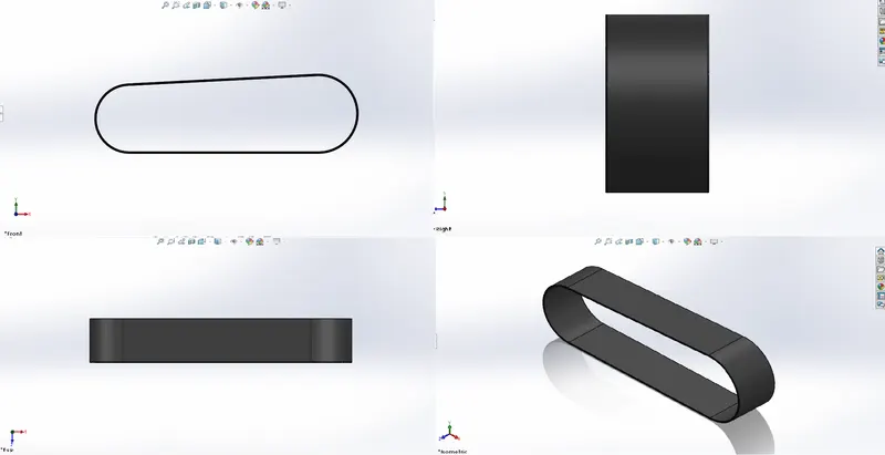
KICK STAND:
A kickstand is a device on a bicycle or motorcycle that allows the bike to be kept upright without leaning against another object or the aid of a person. A kickstand is usually a piece of metal that flips down from the frame and makes contact with the ground.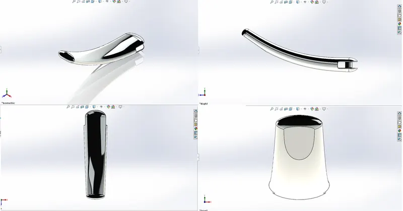
FRONT FENDER:
Fenders make a tremendous difference when you are riding roads that are wet from drizzle, recent rain, or snowmelt. In a hard rain, you may become wet with clean rain from above, but fenders will protect your body and bicycle from the mud and sand kicked up from dirty puddles and rivulets.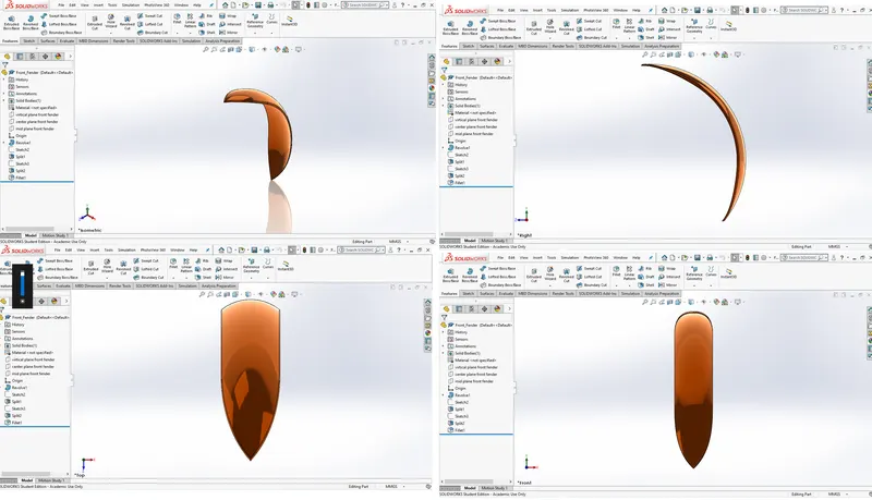
REAR FENDER:
It is same as front fender but it is on the back side.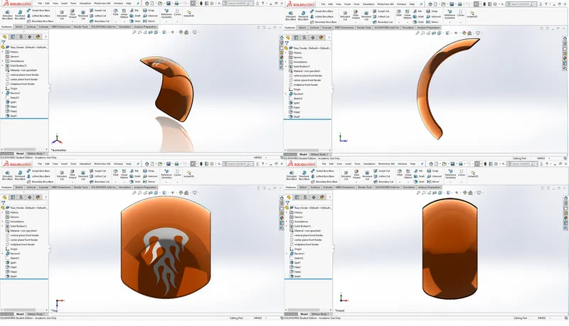
CHAIN:
The chain on the bike, is responsible for transfering the mechanical power from the engine t the wheel of the bike.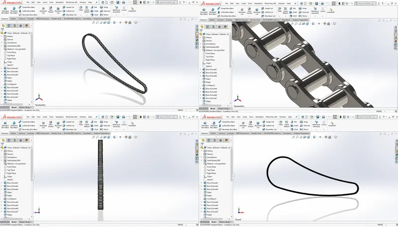
OIL TANK:
A oil tank has the purpose of storing lube oil lubricate the engine parts to avoid wear and tear due to extreme heat.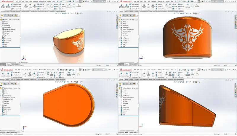
PEDAL:
Pedal ensure that your on-road balance is right and you can avoid any untoward mishap.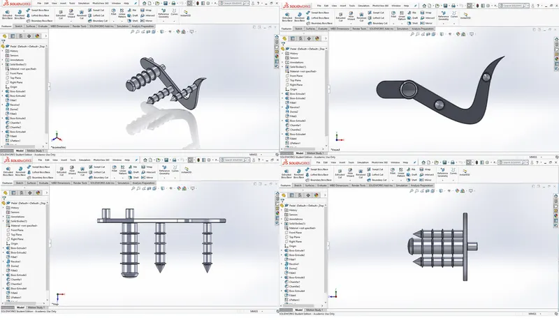
FRONT WHEEL:
Any wheel that is present at the front of a motor vehicle.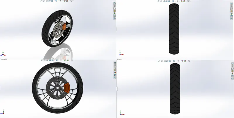
REAR WHEEL:
Any wheel that is present at the back of a motor vehicle.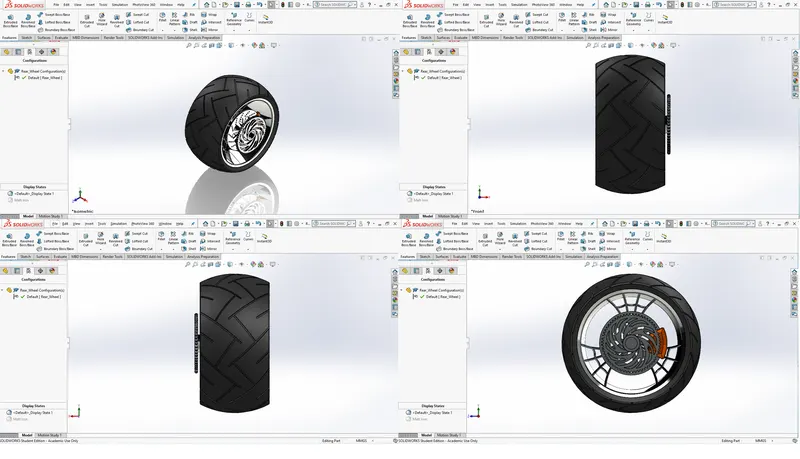
FRONT FORK:
The front fork prevents excessive weight on the front wheel during drastic sudden applications the break, softens bumping when driving on rough road surfaces. The front fork maintains proper damping through traction with the road surface.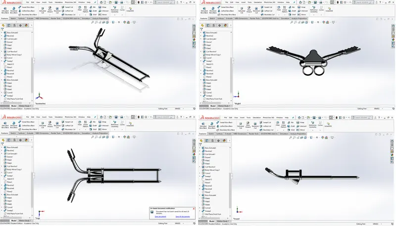
CHASSIS:
The metal frame of a vehicle onto which the other parts fit.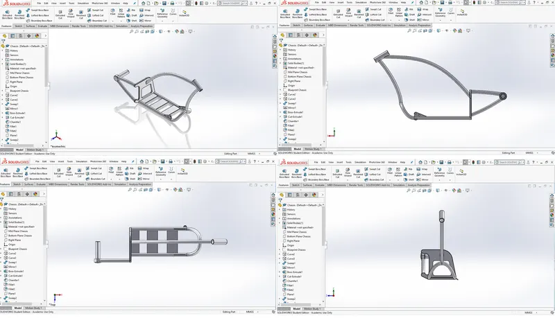
ENGINE:
A machine for converting thermal energy into mechanical energy or power to produce force and motion.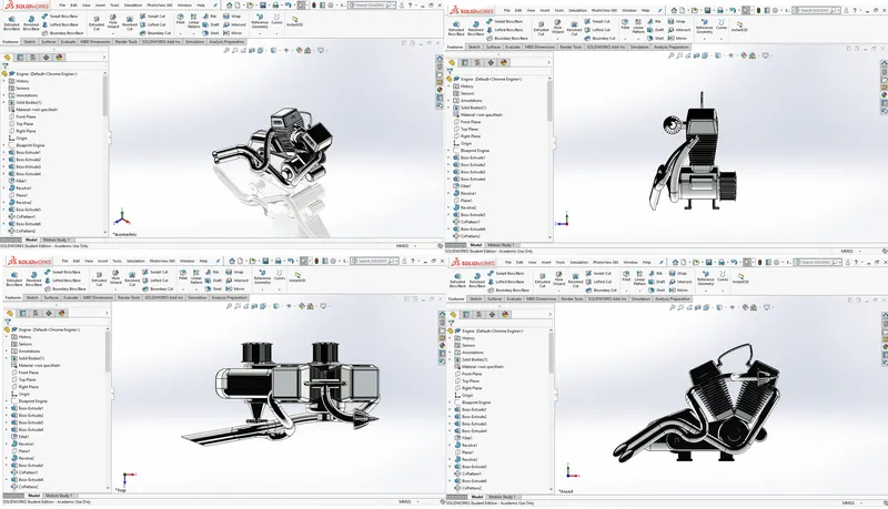
GAS TANK:
A Gas tank also called a petrol tank or fuel tank is a safe container for flammable fluids. Though any storage tank for fuel may be so called, the term is typically applied to part of an engine system in which the fuel is stored and propelled or released into an engine.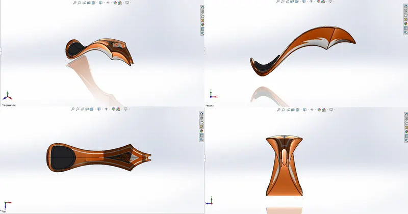
ASSEMBLY OF THE AMERICAN CHOPPER
First the chaassis is inserted and entered so that the chassis is inserted in a way that all the planes of the chassis are coincide with all the planes of new assembly file.
Next all the parts are mated with the useful mate options like standard, advanced etc and the assembly is done.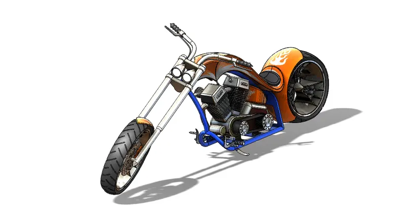
APPEARANCE OF THE AMERICAN CHOPPER
RENDERING
Rendering is the process of generating a photorealistic or non-photorealistic image from a 2D or 3D model by means of a computer program.
There are two types of rendering in solidworks
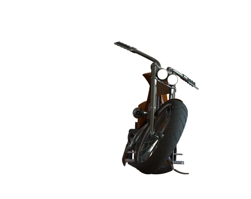
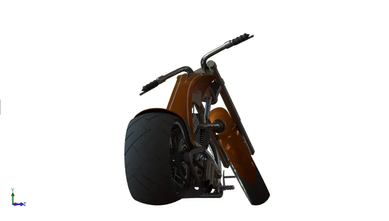
1.SOLIDWORKS PHOTO VIEW 360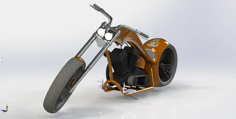
2.SOLIDWORKS VISUALIZE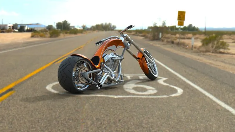
CONCLUSION
Hense the AMERICAN CHOPPER is Assembled and completed with final renderings using SOLIDWORKS PHOTO VIEW 360 and SOLIDWORKS VISUALISE.