Advanced Sheet Metal Design Using NX Cad Challenge_1_Casing Design
A REPORT ON
Designing a 'sheetmetal Casing' using Siemens NX Sheetmetal Application
Etikala Surajkumar
Mechanical
CONTENTS
OBJECTIVE
INTRODUCTION
DESIGN METHODOLOGY/APPROACH
DESCRIPTION
3D VIEWS OF SHEETMETAL CASING
DRAWINGS OF SHEET METAL CASING
OBJECTIVE
The main objective of this project is to Design a 3D model of an Sheetmetal Casing using Siemens NX Sheetmetal Application
INTRODUCTION
Sheet metal is metal formed by an industrial process into thin, flat pieces. Sheet metal is one of the fundamental forms used in metalworking, and it can be cut and bent into a variety of shapes. Countless everyday objects are fabricated from sheet metal. Thicknesses can vary significantly, extremely thin sheets are considered foil or leaf, and pieces thicker than 6 mm (0.25 in) are considered Plate steel or Structural steel.
DESIGN METHODOLOGY
- DESIGNING THE SHEETMETAL CASING
- DRAFTING THE FLAT PATTERN OF SHEETMETAL CASING
DESCRIPTION
TYPES OF FEATURES
SKETCH - LINE, RECTANGLE, CIRCLE, STUDIO SPLINE, POINT
TAB
NORMAL CUT-OUT
BEND
FLANGE
BREAKING CORNERS
UNBENDING
HOLE
DIMPLE
BEADS
MIRROR
REBENDING
FLAT PATTERN
DRAFTING
STEP BY STEP PROCESS
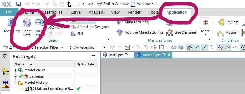
First after opening the NX CAD Application we need to select the 'APPLICATION' tab and in that select the 'SHEET METAL' because the our 3D model is going to be in sheet metal
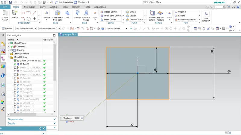
First the sketch is prepared by drawing a rectangle in XY plane of 60*50mm
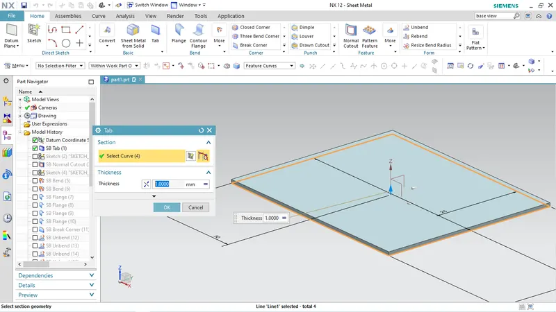
Then the TAB is created using this above Sketch by keeping the wall thickness as 1mm
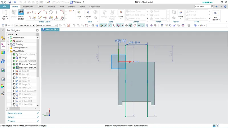
Now another sketch is prepared to make a normal cut out of 5*40mm as shown in figure
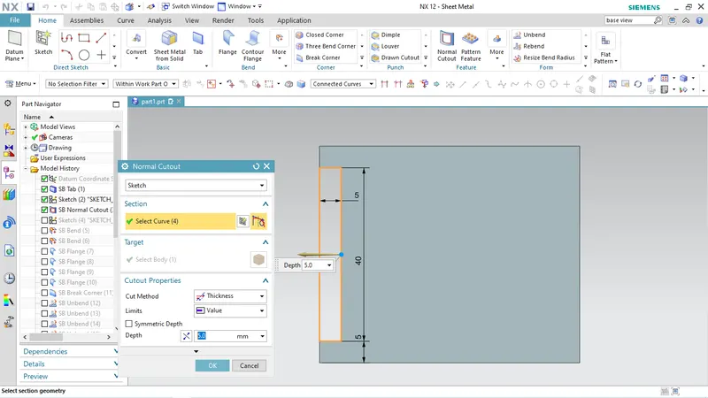
SKETCH
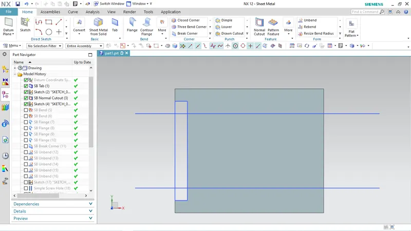
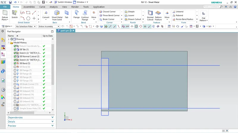
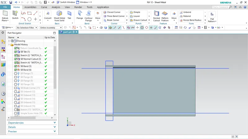
Two parallel lines are created as shown in figure required for Bend tool
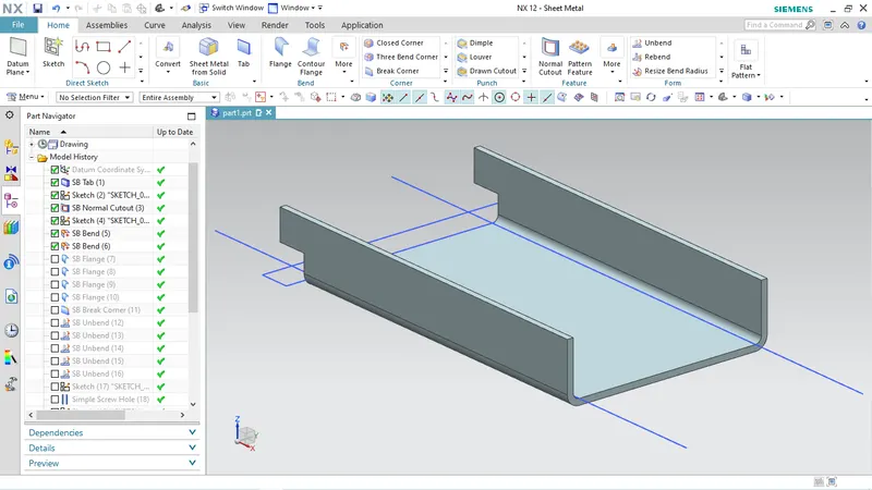
BENDING
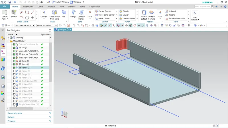
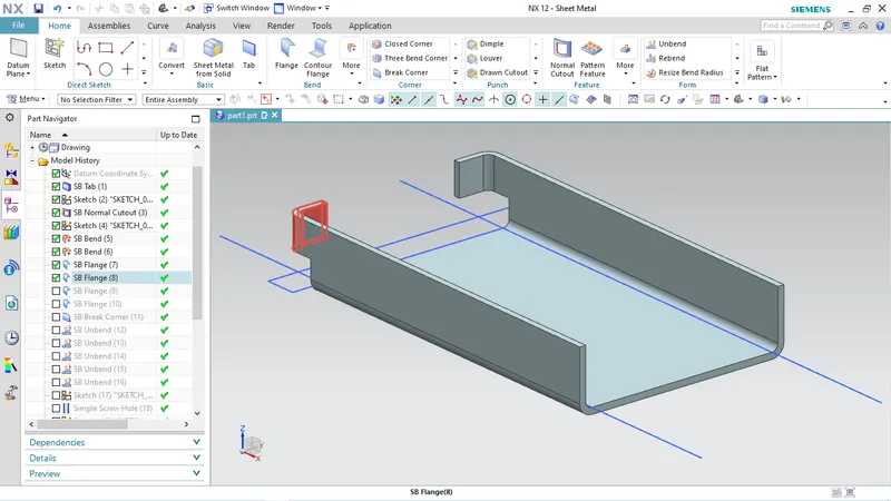
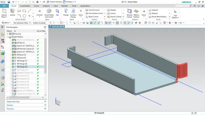
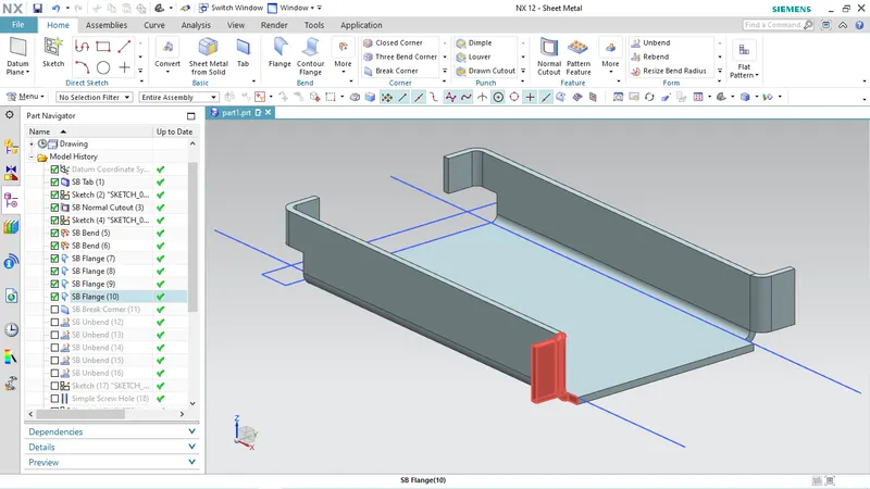
FLANGES
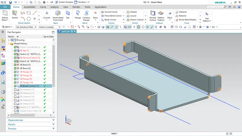
BREAKING CORNERS
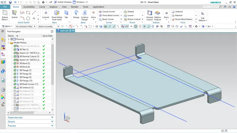
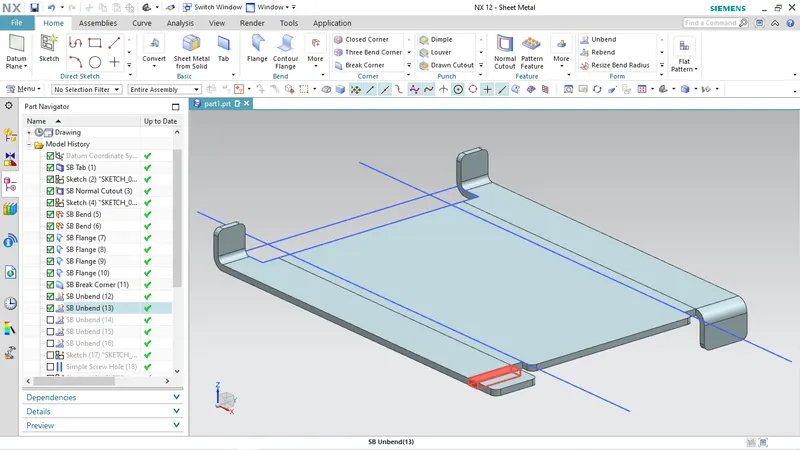
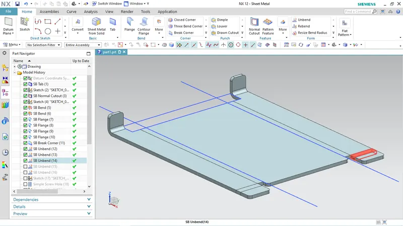
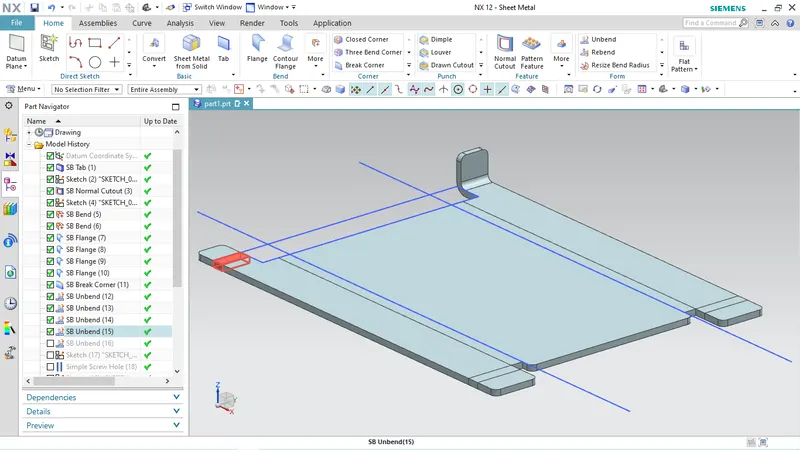
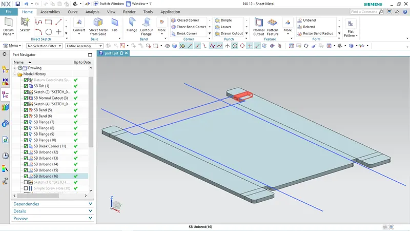
UNBENDING
SCREW HOLES
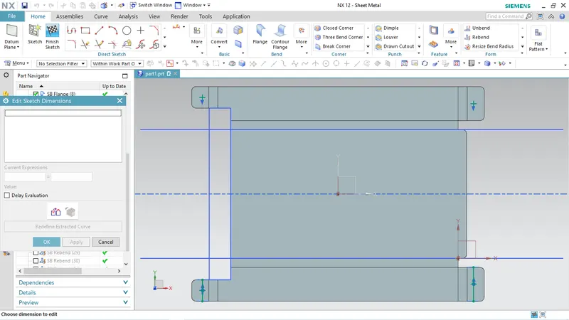
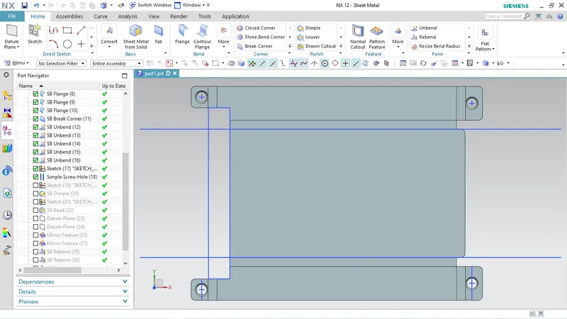
DIMPLE
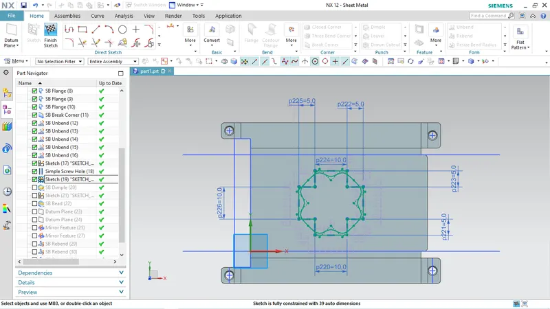
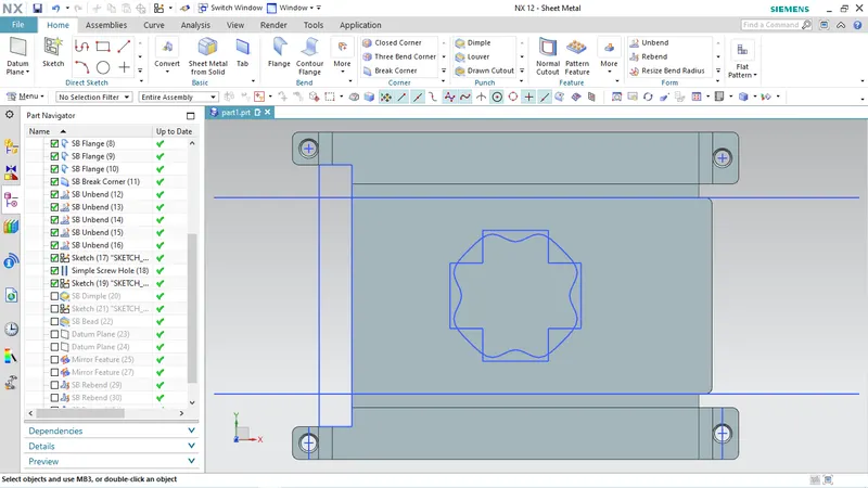
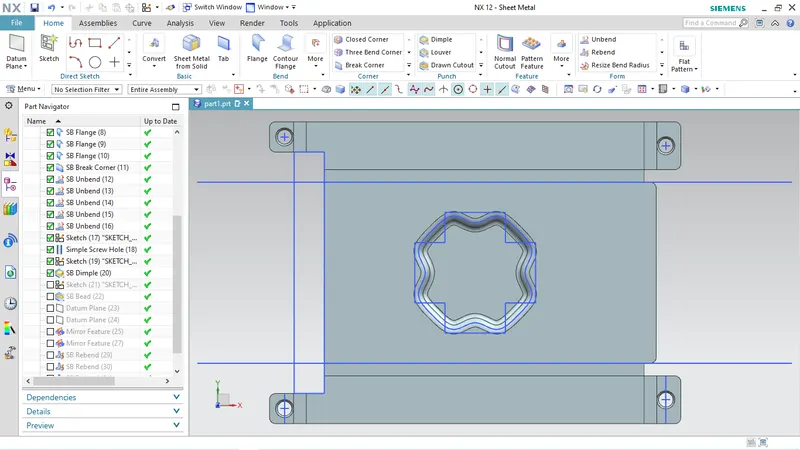
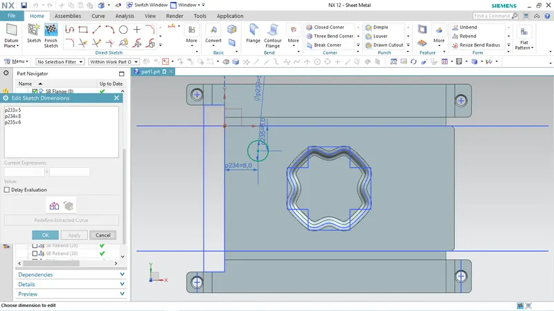
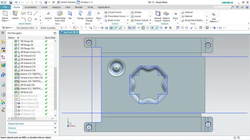
BEAD
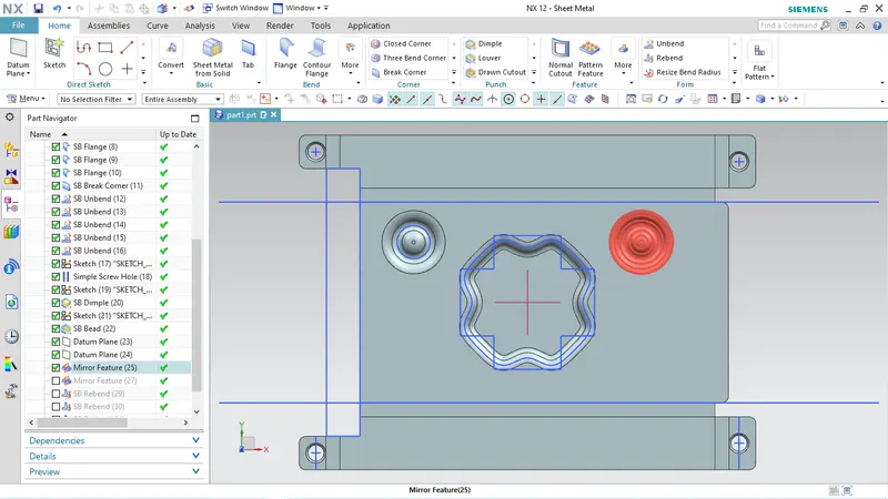
MIRROR of BEAD's Created
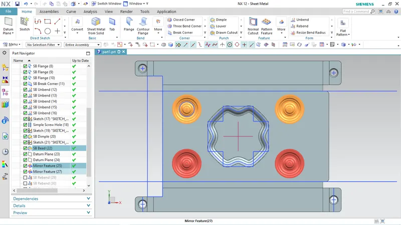
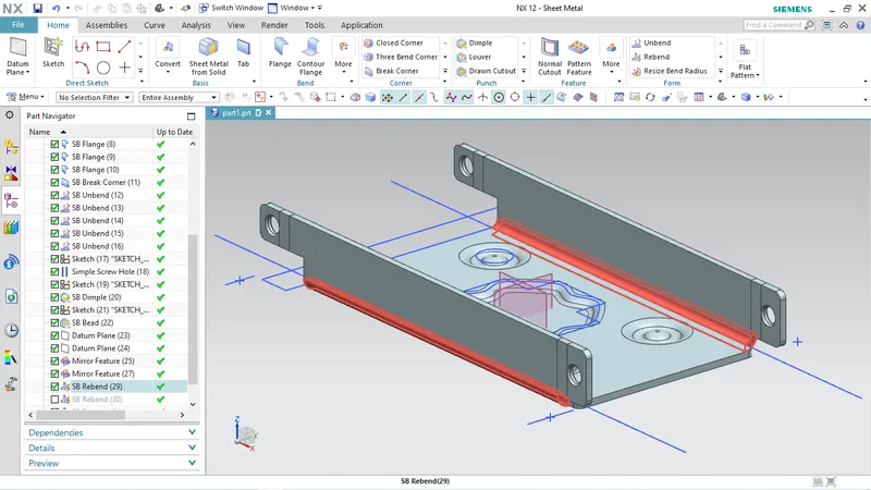
REBENDING
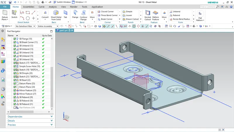
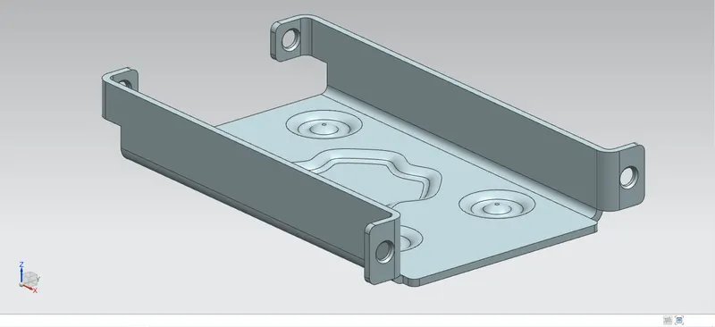
Here is the final 3D model of sheet metal Casing
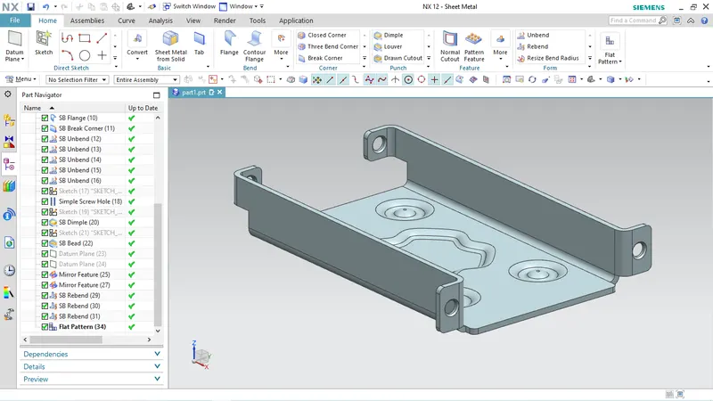
VIEWS
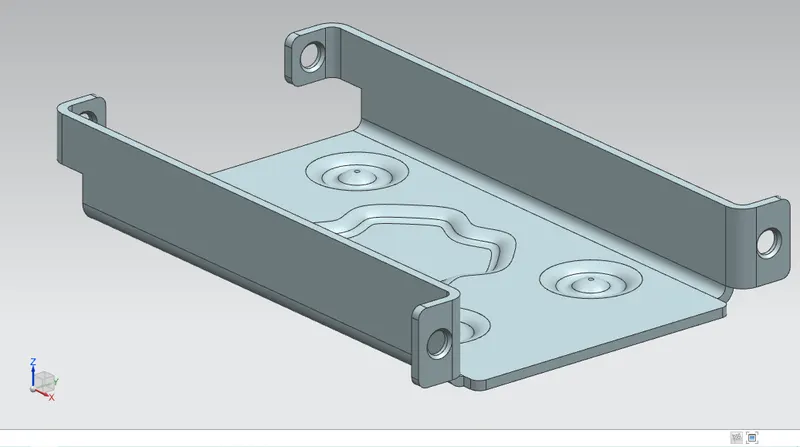
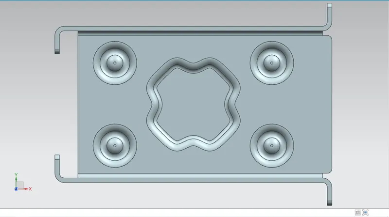
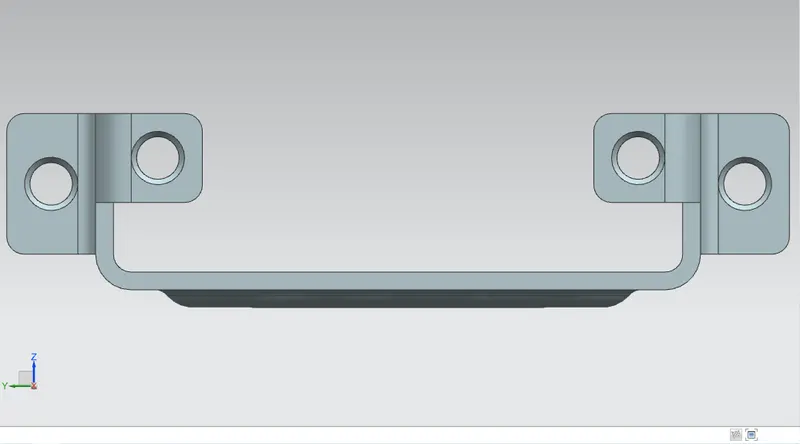
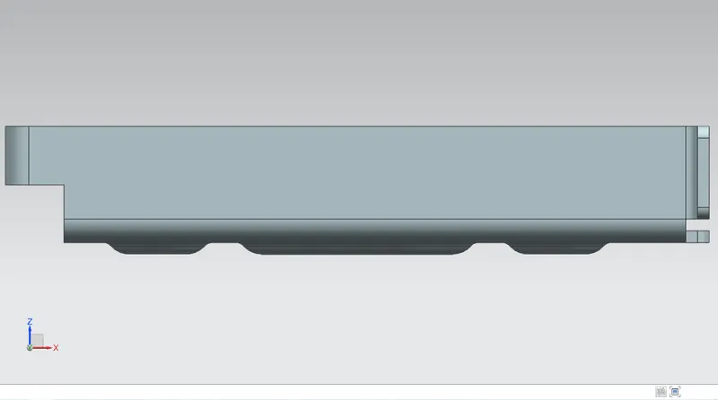
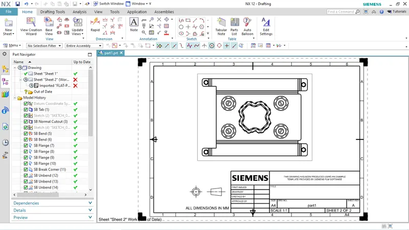
DRAFTING
CONCLUSION
Hense the 3D model of an Sheetmetal Casing using Siemens NX Sheetmetal Application is done.